Barrett BCA40020 User manual
Operating Manual
Barrett Desktop Console (BCA40020)
BCM40020/2
© Barrett Communications
s/w v1.6.2


3
Contents
INTRODUCTION 1.......................................................................................... 5
Terms and Abbreviations ...............................................................................6
Console Diagrams .........................................................................................7
Desktop Console (front)...........................................................................7
Desktop Console (side) ............................................................................7
Desktop Console (rear).............................................................................8
Basic Functionality.........................................................................................9
Switches ..................................................................................................9
SET-UP SCENARIOS 2................................................................................ 11
Scenario 1 ...................................................................................................11
Connection Diagram..............................................................................12
Enabling Remote Head Mode ................................................................13
Scenario 2 ...................................................................................................16
Connection Diagram..............................................................................17
Disabling Remote Head Mode ...............................................................18
SPECIFICATIONS 3 ..................................................................................... 19
Connectors..................................................................................................19
Aux Control Head / BoB Connector ........................................................19
Dimensions..................................................................................................19
Limited 3 Year Warranty Statement.............................................................20
Contact Details ......................................................................................21

4

5
INTRODUCTION 1
The Barrett Desktop Console is designed to work in conjunction with a Barrett
4050 HF SDR Transceiver.
The Barrett Desktop console incorporates a 4050 Control head for full trans-
ceiver functionality, IP or direct connectivity to transceiver, external 24V power
supply, desk microphone and USB interface. It has a built in speaker, detacha-
ble boom microphone and supports standard headsets and PTT (push to talk)
foot switches.
For more information on networking and operation, please consult the Barrett
IP Connectivity Guide (P/N BCM40507) and/or Barrett 4050 HF SDR Operating
Manual (BCM40500) respectively.

6
Terms and Abbreviations
Term Denition
HF High Frequency
IP Internet Protocol
PTT Push to Talk
SDR Software Dened Radio
USB Universal Serial Bus
7
Console Diagrams
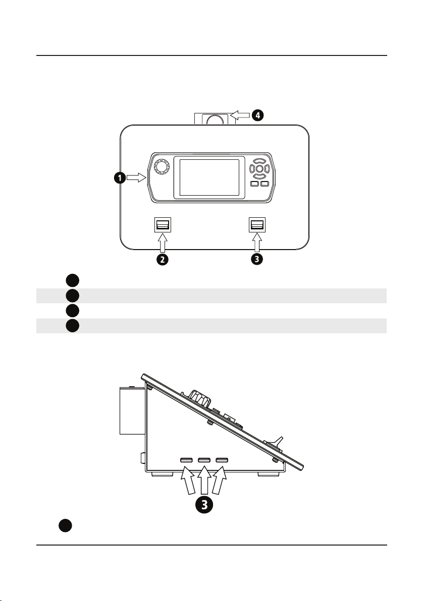
Desktop Console (front)
1
Barrett 4050 HF SDR Transceiver Control head (P/N BCS40005)
2PTT switch - Momentary
3
PTT switch - Latched
4Boom mic connection
Desktop Console (side)
1
USB 2.0 Ports for WiFi Adaptor, data import/export or rmware
upgrade.

8
Desktop Console (rear)
1
Barrett 4050 HF SDR Transceiver (P/N BC40500)
2
Control head control cable - 6 metres (P/N BCA40005)
3Headphones (P/N BCA40013) or Headset with Boom mic (P/N
BCA40040) connection
4
PTT Foot switch connection (P/N BCA207642)
512V DC Power input
6
Ethernet (RJ45)
1
2
34
5
6

9
Basic Functionality
The Barrett Desktop Console has the same functionality as a Barrett 4050
control head with the PTT switches on the front of the console acting as the
microphone PTT connected to the standard 4050. These switches initiate
transmit mode in the transceiver.
For further information regarding the operation of the Barrett 4050 HF SDR
Transceiver, please refer to the Barrett 4050 HF SDR Transceiver Operating
Manual (P/N BCM40500).
Switches
The right-hand switch is latched PTT.
Flick the switch downwards for continuous transmission. Transmit mode will
be halted only when the switch is returned to the neutral position
The left-hand switch is momentary PTT.
Holding this switch up or down will initiate transmit mode on the transceiver.
Releasing the switch will end transmission.
Note: If connected to a foot switch, the foot switch will act as momentary PTT
when pressed. Functionality of the Desktop Console switches is retained.

10

11
SET-UP SCENARIOS 2
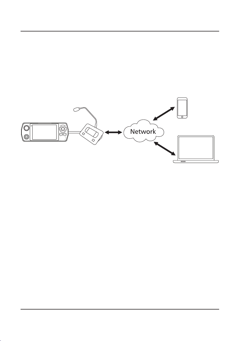
Scenario 1
In this scenario, the desktop console and any other devices are connected to a
Barrett 4050 HF SDR Transceiver via a network as shown in the digram below.
This set-up has particular applications for situations where an operator is
stationed in a different room or location to the transceiver. Full functionality
of the transceiver is retained.
For further detail on the types of networked congurations available, please
refer to the Barrett 4000 Series IP Connectivity Guide (P/N BCM40507).
12
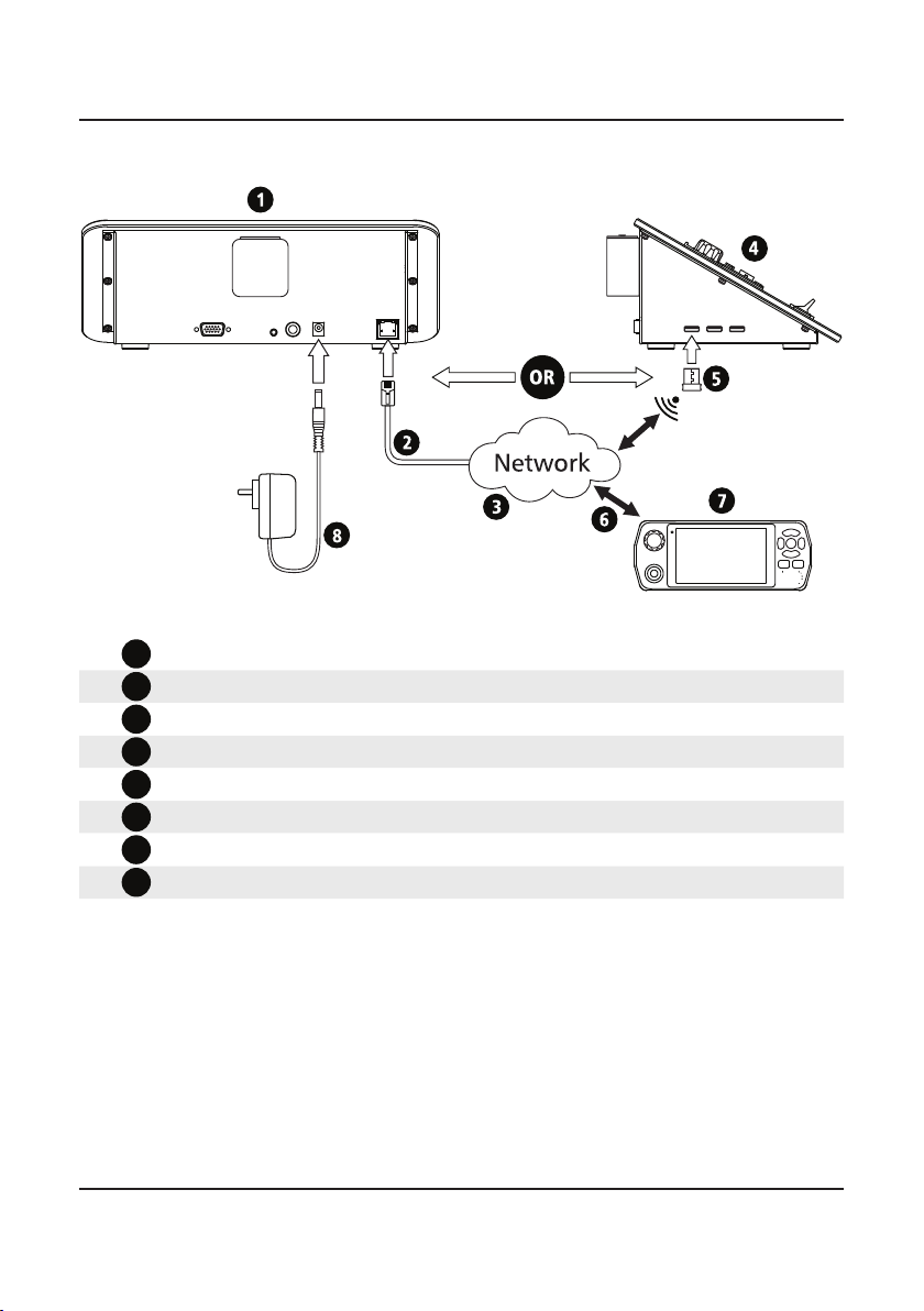
Connection Diagram
1Desktop console (rear) (P/N BCA40020)
2
Ethernet (RJ45) cable
3
Local or Wide Area network
4Desktop Console (side) (P/N BCA40020)
5WiFi Adaptor (P/N BCO40508)
6
Wired or Wireless network connection
7Barrett 4050 HF SDR Transceiver (P/N BCA40500)
8
12V DC Power Input

13
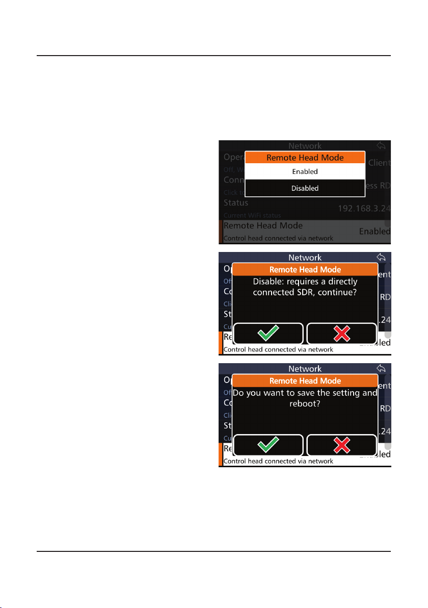
The Desktop Console must be congured into ‘Remote Head Mode’ to func-
tion correctly via network. The following instructions lay out how to congure
a desktop console to Remote Head Mode when connected via a network:
Enabling Remote Head Mode
1. Ensure the desktop console is
connected via a 12VDC power
supply via the input on the rear
of the console.
2. A communication error may
occur as the console will
attempt to connect to a
transceiver. Acknowledge the
dialogue box.
(This will only appear if the
Desktop Console was not pre-
viously in Remote Head Mode).
3. Swipe from the left edge of the
screen and select Settings.
4. From Settings, long press the
Network icon. This will unlock
the ‘Remote Head Mode’ fea-
ture in the Network menu.
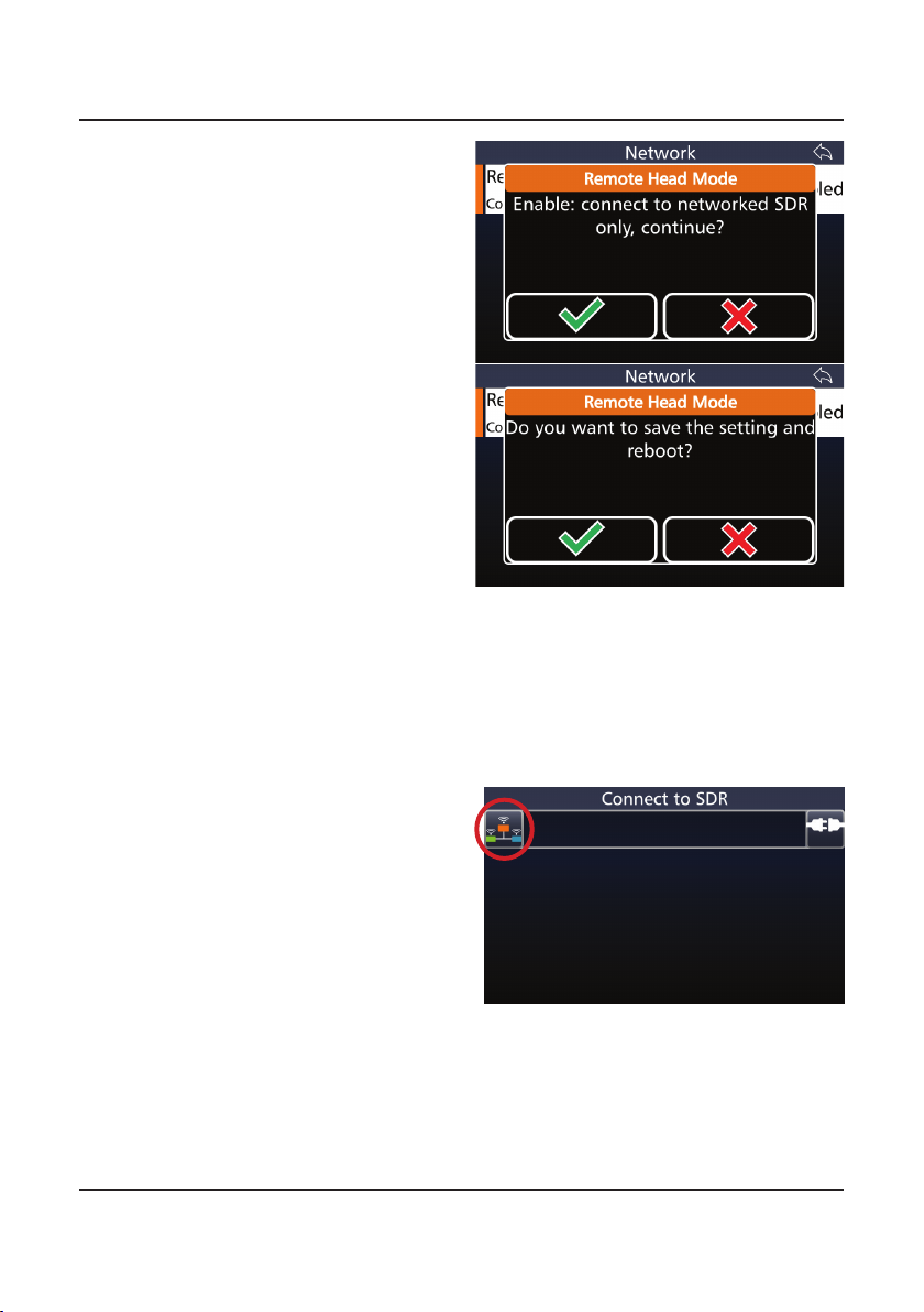
5. Select ‘Remote Head Mode’
and select ‘Enabled’.
14
6. Select the green ticks when
prompted. The head will
restart.
After the reboot:
7. Insert a USB WiFi adaptor into
a USB port on the side of the
console or connect to the net-
work via Ethernet cable.
8. Congure the network (as per
IP Connectivity Guide)
9. Press the “Network” button on
the left

15
10. Congure the network
11. Return to main screen
12. Select one of the listed SDRs
or enter the IP address / host
name into the top eld
16
Scenario 2
In this scenario, the desktop console is directly connected to the Barrett 4050
HF SDR Transceiver by a 15-way cable. All other devices connect to the desk-
top console via a network as shown in the diagram below.
Here, the desktop console acts a as a secondary control head and has appli-
cations primarily for situations needing the added security of a direct connec-
tion. This includes situations when multiple personnel wish to monitor the
same transceiver but are still located in the same room.

17
Connection Diagram
14050 HF SDR Transceiver
2
Control Head control cable
3Desktop Console (rear)
4
Ethernet (RJ45) cable
5
Network
6Barrett WiFi Adaptor
7Desktop Console (side)
18
Disabling Remote Head Mode
1. If already connected to a SDR,
go to "Settings", long press on
"Network" icon. If not con-
nected to any SDR, long press
the “Network” icon on the
left of the “Connect to SDR”
screen.
2. Select "Remote Head Mode",
then select "disabled"
3. Answer the questions with
the green tick ("yes"). The
transceiver will reboot and
the Desktop Console can be
disconnected.
Remote Head Mode will need to be disabled when moving a desktop console
from a networked conguration to a directly connected one. The following
instructions outline this procedure.
In all other case, set up as directed in Scenario 1.
19
SPECIFICATIONS 3
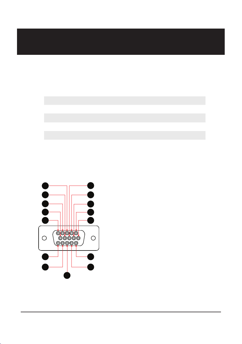
Aux Control Head / BoB Connector
These pins are dependant on hardware revisions. Revisions are marked in the table
below as Ax where x is the revision number. The revision number can be viewed
under Settings < System Info < Version Information.
1. VCC
2. CAN Bus positive pin
3. CH Audio+
4. Rear speaker+
5. Ground
6. Ground
7. CAN Bus negative pin
8. CH Audio-
9. Rear speaker-
10. CAN bus termination
11. Control Head detection
12. not connected
13. USB+ (A11 or later)
14. USB- (A11 or later)
15. USB 5V (A11 or later)
11
12
13
14
15
1
2
4
5 6
7
8
9
10
3
Connectors
Standard Connectors: 12V DC Power Supply
boom mic socket (female XLR)
Ethernet (RJ45)
USB 2.0
PTT (6.35mm mono)
Headphone (3.5mm 4 position jack (TTRS))
Dimensions
185mm (l) x 270mm (w) x 105mm (h)
For specications regarding the operation of the Barrett 4050 HF SDR Trans-
ceiver Control head, please refer to the Barrett 4050 HF SDR Transceiver Oper-
ating Manual (P/N BCM40500).

20
Warranty Statement
Barrett Communications (hereafter referred to as ‘Seller’) provides a three
(3) year warranty on all Barrett products from the date of shipment from the
Seller. A one (1) year warranty from the date of shipment from the Seller is
provided for all batteries.
Each warranty guarantees acceptable performance of the product under
normal recommended conditions for the duration of the warranty period. In
cases of accident, abuse, incorrect installation or maintenance by a non-Seller
representative, subjection to abnormal environmental conditions, negligence
or use other than those in accordance with instructions issued by the Seller,
the warranty shall be voided. In addition, this warranty shall not cover low
performance – specically the distance or quality of transmission and recep-
tion - due to unfavourable environmental or locational conditions. Nor shall
this warranty cover the quality of transmission and reception of transceivers
mounted in vehicles or vessels that have not been sufciently electrically sup-
pressed.
Should any fault due to bad design, workmanship or materials be proven
at any time within the warranty period, the Seller will rectify such fault free
of charge provided that the equipment is returned, freight paid, to Barrett
Communications Pty Ltd head ofce or to an authorised service centre. The
repaired or replaced product will remain covered under and throughout the
term of the original warranty period up to its expiration. No repair or replace-
ment will extend the warranty term past the original thirty-six (36) month
anniversary of the original date of shipment from the Seller.
Firmware and software (pre-installed, stand-alone or provided as an update),
hereafter referred to as ‘Software’, is guaranteed to perform acceptably within
the specications provided by the Seller, provided that the Software is within
the warranty period.
Should Software not perform acceptably, the Seller will use all commercially
reasonable efforts to correct such nonconformity as reported to the Seller
directly or via a support representative. The Seller is not obliged to update
Software under warranty if the nonconformity is caused by a) the use or
operation of the Software in an environment other than intended or recom-
mended by the Seller in relevant documentation, or b) modications made to
the Software not authorised or undertaken by the Seller or a representative of
said Seller.
Subject to the matters set out in this warranty, no liability, expressed or
implied is accepted for any consequential loss, damage or injury arising as a
result of a fault in the equipment and, all expressed or implied warranties as
to quality or tness for any purpose are hereby excluded.
Table of contents


