Issendorff LCN-UT User manual

LCN-UT
Installation guide Local Control Network - building controls in perfection
1
Flush mounted transponder module for LCN
The LCN-UT is a transponder evaluation system to intregate in the LCN Bus. Included in
delivery apart from the module for flush mounting, are three flat antennas in different sizes,
that can be optionally installed. The largest antenna covers the largest range, approx.
30cm. For special applications (e.g. in joints between wall tiles), self wrapped antennas
can be made.
LCN-UT
ISSENDORFF KG
Spannungsfrei installieren!
1 2 3 4 5 6
I-
Port
Ant. V
power supply:
10-18V =
(e.g. LCN-NU16 or
LCN-NH12)
optical verification
for voltage, flashes
when a transponder
is detected.
to the I-port
of the LCN module
antenna
miniature switch for
matching the antenne
V
Voltmeter
(only for fine setting)
+10-18VDC
GND
P 0,9W
max
Rot/red
Grün/green
®

LCN-UT Installation guide
Local Control Network - building controls in perfection
2
Included in delivery:
LCN-UT, 3 antennas & 2 transponders (1 ZTK & 1 ZTS).
Connection
The LCN-UT is for connecting to the I-port of all LCN Bus modules with firmware 0E....
(Jan. 2005) or after. The supply line can be extended up to 50m by using 2 LCN-IV´s.
The following peripheries can be used on the I-port parallel to the LCN-UT: LCN-GBL, -
RR, -ULT, -GT2, -GT4D, -GT10D, -GT3L, max. 1 further -EFS, but no more than 5 I-
periphery devices on one I-port at the same time.
Operating the LCN-IV as impulse counter/counter input is not possible!
Additionally, the LCN-UT needs a power supply of 10-18V DC. for this, an LCN power supp-
ly like the LCN-NH12 or LCN-NU16 can be used.
Because the LCN-UT is electrically isolated from its LCN module, several LCN-UT modules
can use the same power supply.
Function
The LCN-UT must be activated with the LCN-PRO under Ports > I-port. Then
the LCN module will send the transponder code to the LCN Bus when the antenna is
approached. It can be displayed on the Bus monitor (LCN-PRO: key <F8>) and evalua-
ted with the LCN-GVS for access control.
Important:
®

3
Installation guide Local Control Network - building controls in perfection
The LCN module can trigger a key additionally - it sends the “HIT” command. Up to 16
transponder cards can be assigned to an individual key. To do this, the input window
<TRANSPONDER> in the LCN-PRO must be opened and the serial number of the card with
the corresponding key (e.g. D3) registered. The serial number is a 6 figure combination
of letters and numerals. This can be determined on the Bus window beforehand.
To recognise non authorised cards, a serial number with 00 00 00 can be registered on
position 16. The LCN module then always sends out the assigned key, when it recogni-
ses a non assigned serial number. .
Note about function:
To parameterize the transponder, the LCN-PRO is needed and modules with firmware
0E.... (year 2005) or after. After the module firmware 10.... (year 2006 or later), the LCN-
UT has to be unlocked in the module properties.
Transponder cards:
For testing the functions, two different transponders are included in the delivery. The
card (illustr., page 4) achieves the largest range. Due to the fact that the LCN-UT
uses a standard protocol, the receiver reacts to many other sytems. Additionally
JUNGHANS offers wrist watches with built in transponders.
LCN-UT
®

LCN
illustr. 1: transponder chip card,
LCN-ZTK
Description of the transponders:
illustr. 2: keyring,
LCN-ZTS
4
Installation guide
Local Control Network - building controls in perfection
LCN-UT
®

5
Installation guide Local Control Network - building controls in perfection
installation/range:
LCN-UT can be installed in every standard flush mounted box, due to its small dimensions.
Please plan enough space for a power supply and an LCN-UPP, if these are to be installed
in the same area (2 deep flush mounted boxes).
The antennas are provided for installing in the wall or floor. The larger antenna offers more
range. (see technical data on page 12).
The antennas are very flat, so they can be optionally plastered or wall papered over. The in-
ner diameter is specially chosen, so that the large antenna can be installed over a double
flush mounted box, the middle one over a single flush mounted box. The small antenna fits
in most of the traditional switch blind covers.
For special installation places, e.g. in the joints of bricked walls or under paving stones, the
antennas can be individually wrapped. See also page 9.
The polarity of the antenna connecting cable is optional.
LCN-UT
®

6
Installation guide
Local Control Network - building controls in perfection
LCN-UT
Important notes about installing:
·
Only one of the antennas can be operated on the LCN-UT, connecting two antennas par-
allel is not possible.
·
No large metal parts directly nearby! With very strong reinforced concrete, the installation
area should be tested first of all. Metal rings from switch blind covers, cause a short circuit:
Saw the ring apart on one area completely. The ring must not be closed.
·
Televisions, monitors and similar interfering sources directly nearby (approx. 1 m) to the
antenna, reduce the range!
·
With a fine setting using a volt meter, avoid any unnecessary short circuits that may occur
on the connection terminals!
·
The flush mounted power supply LCN-NU16 should not be installed directly on or under
the LCN-UT module, otherwise the range can be reduced through the coupling on the
transformer. There are no limitations when installed directly beside the LCN-UT .
·Always install the LCN-UT with the power switched off! Even the antenna
must only be connected or disconnected with the power switched off!
Important:
®

7
Installation guide Local Control Network - building controls in perfection
Choosing and setting the antenna:
for optimating the range, the LCN-UT allows a matching for the antenna, then the inductivity
depends on the size of the antenna and the installation area. When no or just small metal
parts are lying near the antenna, the following settings will give an acceptable range:
Switch settings with large
antenna:
Switch settings with middle
sized antenna:
Switch settings with small
antenna:
it is better to match the antenna, see following page.
10-18V
1 2 3 4 5 6
1 2 3 4 5 6
1 2 3 4 5 6
1 2 3 4 5 6
LCN-UT
ISSENDORFF KG
LCN-UT
®

8
LCN-UT Installation guide
Local Control Network - building controls in perfection
Fine matching (for maximum range):
If the given ranges are not reached as shown on page 12, or when the maximum range defi-
nitely has to be reached, A matching of the antenna is recommended. To do this, the com-
bination of the miniature switches are searched to find which one gives the optimal range.
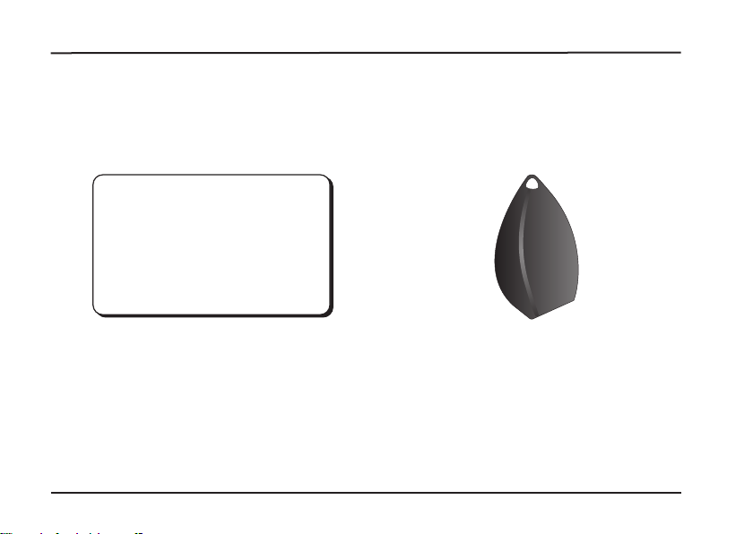
If no further tools are available, a transponder card and a folding ruler will be enough:
Approaching attempts are repeatedly made and the miniature switches adjusted between
times.
It is more comfortable and quicker with a volt meter: To make the matching simpler, the
LCN-UT is equipped with a measuring device for the antenna voltage. The AC antenna vol-
tage can be measured with the help of a multimeter on the measuring terminals (see illustr.
page 1.) Please try to avoid possible short circuits when fine matching on the measu-
ring terminals!
The aim is to match, so that theAC voltage is at amaximum.
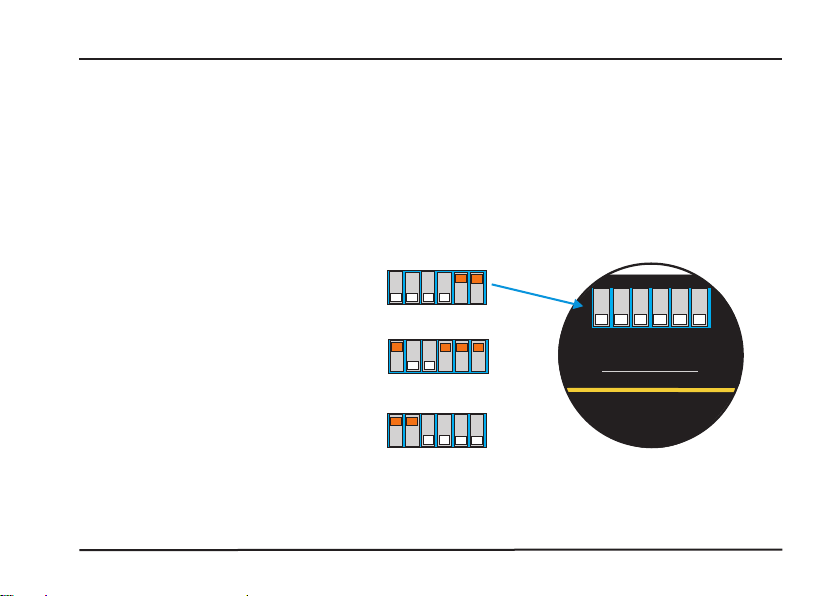
Matching instructions:
push all switches towards the bottom (see illustr. page 7). The matching begins with switch
1 (rough matching). Push the switch towards the top. If the voltage rises, leave the switch
there. if the voltage drops, push the switch back down. Do this in the same way with the swit-
ches 2, 3, 4, 5 and 6. Please be aware of the order, switch 6 allows the finest step.
®

9
Installation guide Local Control Network - building controls in perfection
Antenna wrap description:
area of the antenna cm²
amount of
antenna
coils
6 7 8 9 11 12 13 14 15 1610
0
7000
6000
5000
4000
3000
2000
1000
2500
example
LCN-UT
®
crossing point

10
LCN-UT Local Control Network - building controls in perfection Installation guide
To determine the optimal amount of coils for the antenna, first the area of the desired
antenna has to be calculated. It does not make any difference if the antenna should be
round or square shaped. Now the calculated area is followed down vertically from the
curve as shown in the graphic (page 9). Under the crossing point of the curve (see
example, page 9), you can read the optimal amount of coils.
In the example (marked in blue) an antenna with an area of 2500 cm² (e.g. 50x50 cm), 10
coils.
Should the crossing point lie between two coils, the next smaller amount of coils should be
chosen.
To wrap the antenna, standard fine wire with 0,75 mm² or 0,5 mm² should be used. The
connection cable to the self wrapped antenna, should be kept short!
Notes about self wrapped antennas:
!Antennas over 5000 cm² need (due to performance reasons) a stronger power supply,
e.g. LCN-NH12 or similar.
!After finishing the wrapping, carry out a fine matching!
!The maximum range of the antenna, depends on its form. Good results are achieved
with long forms. When over 5000 cm², the range reduces. Test range before installing!
®

11
Installation guide Local Control Network - building controls in perfection
10-18V DC
max. 1W with 18V;
typical 0,8W / 16V
EM-H 4001, 4002, 4102,
Ø 50 mm, d=20 mm
-10°C...+ 35°C
for use as stationary installation according to
VDE632, VDE637
IP 20 when installing in a flush mounted box
Technical data of the LCN-UT:
power supply:
power consumption:
supported card systems:
casing size:
operating temperature:
environmental conditions:
protection class:
LCN-UT
®

LCN-UT D12/2012
12
Technical information and images are non binding. Changes are reserved.
Technical hotline: +49 5066 998844 or www.LCN.de
LCN-UT Installation guide
Local Control Network - building controls in perfection
Technical data of the flat antenna:
0,4 mm
Ø 245 mm outer, 200 mm inner
appr. 28 cm with card type CFR03 or PF22
Ø 123 mm outer, 86 mm inner
appr. 22 cm with card type CFR03 or Pf22
Ø 50 mm outer
appr. 9 cm with card type CFR03 or PF22
120 mm (non extendable)
thickness/mounting height:
measurement (antenna large):
range:
measurement (antenna middle):
range:
measurement (antenna small):
range:
connecting cable:
ISSENDORFF KG, 31157 Sarstedt
®
Other Issendorff Marine Radio manuals
Popular Marine Radio manuals by other brands

Cobra Marine
Cobra Marine Marine MR HH125 Manual del propietario

Garmin
Garmin VHF 725e owner's manual

Apollo
Apollo SL installation manual

Elatec
Elatec TWN4 MultiTech 3 LF Quick Start Guide/Integration Manual

De Haardt
De Haardt GX-120 quick start guide

Comar Systems
Comar Systems CSB200 Installation and instruction manual