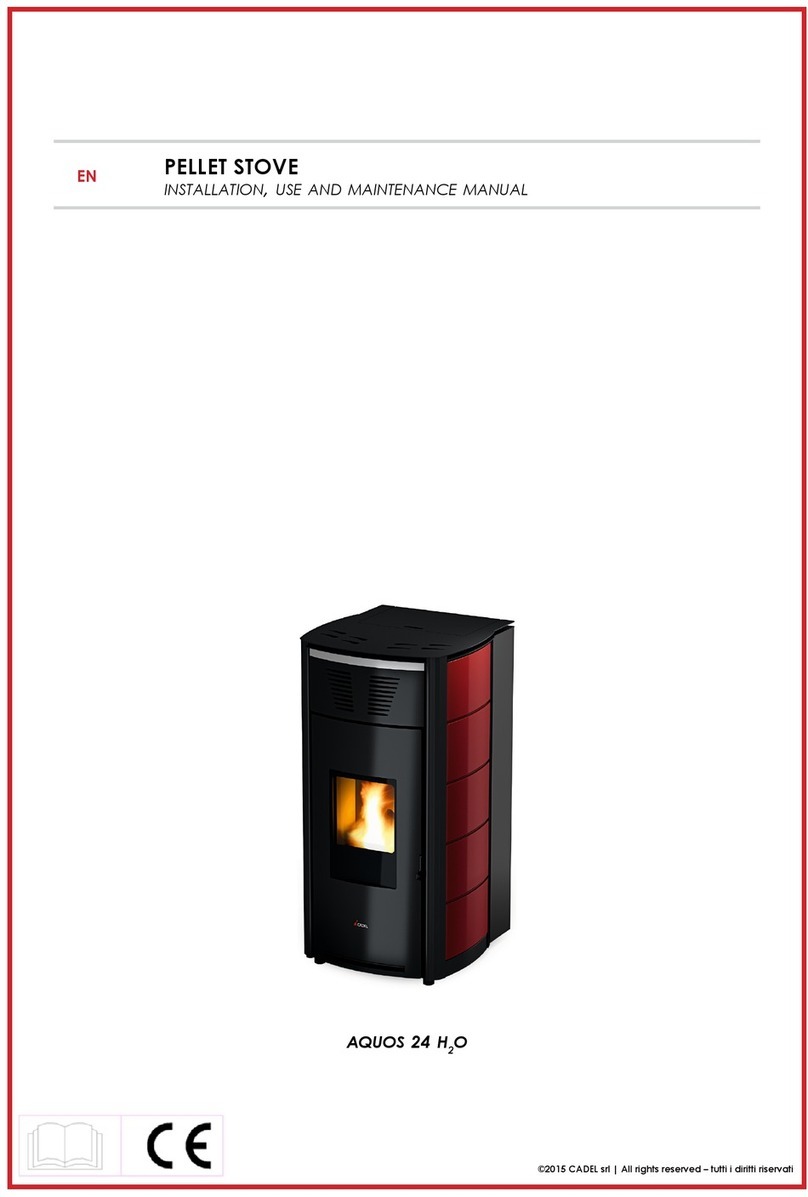
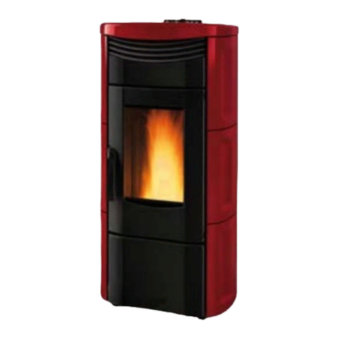
Italiana Camini ELLY IDRO Quick start guide

ELLY IDRO
®
EN Installation, use and maintenance page 2
Pellet boiler stove

2
ENGLISH
Safety information 4
General information 5
Installation 7
Instructions for use 17
Maintenance 21
Troubleshooting 24
CONTENTS
The undersigned company with registered office in Via Vin-
cenzo Monti 47 - 20123 Milan (Italy) - Tax ID Code and VAT
number 00192220192
Hereby declares, under its sole responsibility, that:
The pellet boiler stove mentioned below complies with EU
Regulation 305/2011 and harmonised EU standard
EN 14785:2006
PELLET Boiler Stove, bearing the
ITALIANA CAMINI trademark and called ELLY IDRO
SERIAL NO.: Rating plate reference
Performance declaration: (DoP - EK n° 092):
Rating plate reference
Moreover, the company hereby declares that:
the ELLY IDRO wood pellet boiler stove complies with the
requirements
of the European Directives:
2014/35/EC - Low Voltage Directive
2014/30/EC - Electromagnetic Compatibility Directive

3
ENGLISH
SEQUENZA OPERATIVA:
seguire le istruzioni procedurali per le
operazioni descritte
Dear Sir/Madam
We thank you for and congratulate you on choosing our
product. Before using it, we ask that you read this manual
carefully, in order for you to be able to make the most of all
its functions in total safety.
This manual is an integral part of the product. We ask you
to keep it for the entire lifetime of the product. If you lose it,
you can request a copy from your dealer or download it from
www.italianacamini.com
After unpacking the product, check the condition and
completeness of the contents.
In the event of error, immediately contact the retailer where
the purchase was made, providing him with a copy of the
warranty booklet and the sales receipt.
The appliance must be installed and operated in compliance
with local and national law and European regulations. For the
installation, and for anything not specifically indicated in the
manual, observe local regulations.
The diagrams provided in this manual are for illustration
purposes only: they do not always strictly refer to your
specific model, and are not binding in any way.
MEANING OF SYMBOLS
In some parts of the manual the following symbols are
used:
INFORMATION:
failure to comply with these requirements
will compromise product use.
PLEASE NOTE:
carefully read and understand the
message in question, since failure to
follow the instructions in it could cause
serious damage to the product and put
the safety of those using it at risk.
OPERATING SEQUENCE:
follow the instructions for the operations
described.
The product is uniquely identified by a number, the
“counterfoil”, which is indicated on the warranty certificate.
Please keep:
• the warranty certificate accompanying the product
• the purchase receipt given to you by the retailer
• the declaration of conformity given to you by the installer.
The warranty conditions are given in the warranty certificate
accompanying the product.
In Italy, commissioning by an authorised technician is
required by UNI 10683, and is recommended in all countries
to ensure best results from the product.
This consists in:
• checking the installation documents (declaration of
conformity) and the quality of the installation itself
• calibrating the product to suit its actual application
• providing explanations to the end user and issuing
the complementary documentation (first ignition -
commissioning certificate)
Having the appliance commissioned properly ensures that it
will operate to best effect and in complete safety.
Proper commissioning is required for activation of the
manufacturer's warranty. The warranty is only valid in the
country where the product was bought.
If the appliance is not commissioned by an authorised
technician, the manufacturer will not provide warranty service.
See the warranty booklet for details. The above terms do not
affect the dealer's legal responsibility for the legal warranty.
The warranty, however, covers only demonstrable
manufacturing defects and not, for instance, problems
resulting from improper installation or calibration.

4
ENGLISH
SAFETY INFORMATION
®
• The product is not designed for use by people,
including children, with limited physical, sensory
and mental abilities.
• The appliance is not designed for cooking
purposes.
• The appliance is designed to burn UNI EN ISO
17225-2 category A1 wood pellets, in the amounts
and manner described in this manual.
• The appliance is designed for indoor use and in
areas with normal humidity conditions.
• Keep the product in a dry place out of the weather.
• For the legal and company warranties, refer to the
warranty certificate inside the product: specifically,
neither the manufacturer nor the dealer are liable
for damage resulting from incorrect installation or
maintenance.
Safety risks may be caused by:
• installation in unsuitable conditions. In particular,
conditions of fire hazard. DO NOT INSTALL THE
PRODUCT IN AREAS SUBJECT TO THE RISK OF
FIRE.
• contact with fire and hot parts (e.g. glass panel
and pipes). DO NOT TOUCH HOT PARTS and,
when the boiler stove is switched off and still hot,
always wear the gloves supplied.
• contact with live electrical equipment (internal).
DO NOT ACCESS THE INTERNAL ELECTRICAL
EQUIPMENT WHILE THE APPLIANCE IS
POWERED ON. Electrocution hazard.
• use of improper ignition aids (e.g. alcohol). DO
NOT IGNITE OR BOOST THE FLAME WITH FLUID
SPRAYS OR A FLAME TORCH. Serious risk of
burns, damage and injury.
• use of fuel other than wood pellets. DO NOT
BURN WASTE MATTER, PLASTIC OR OTHER
MATERIALS THAN WOOD PELLETS IN THE
HEARTH. The product may become soiled, the
flue may catch fire, and environmental damage
may ensue.
• cleaning the hearth when hot. DO NOT CLEAN
THE HEARTH WITH A VACUUM CLEANER WHILE
IT IS HOT. Risk of damage to the cleaner and
smoke in the room.
• cleaning the fumes duct with cleaning products. DO
NOT CLEAN THE PRODUCT WITH FLAMMABLE
PRODUCTS. Risk of fire or blowback.
• cleaning the hot glass pane with unsuitable
cleaning products. DO NOT CLEAN HOT GLASS
WITH WATER. ONLY USE RECOMMENDED
GLASS CLEANING PRODUCTS. Risk of cracking
and permanent, irreparable damage to the glass.
• the storage of flammable materials at a distance
which is less than the safe distances listed in
this manual. DO NOT PLACE LAUNDRY ON
THE APPLIANCE. DO NOT PLACE DRYING
RACKS WITHIN THE SAFETY CLEARANCE. Keep
flammable fluids away from the appliance. Fire
hazard.
• blocking the aeration vents and air intakes in the
room. DO NOT BLOCK THE AERATION VENTS
OR FLUE. Risk of smoke returning into the room
with consequent damage and injury.
• use of the product as a support or ladder. DO NOT
CLIMB ONTO THE PRODUCT OR USE IT AS A
SUPPORT. Risk of damage and injury.
• use of the boiler stove with the hearth open. DO
NOT USE THE PRODUCT WITH ITS DOOR OPEN.
• incandescent material projected from the open
door. DO NOT throw incandescent material
outside the appliance. Fire hazard.
• use of water in case of fire. CALL THE AUTHORITIES
if a fire breaks out.
• The appliance must never be used without water
in the system; any “dry” lighting is likely to damage
the appliance.
If you have doubts, please do not take any action, but
contact the retailer or the installer.
For reasons of safety, read the user instructions
included in this manual.
5
ENGLISH
DIMENSIONS
®
DIMENSIONS in cm
ritorno 3/4”
carico/scarico mandata 3/4”
valvola sicurezza3bar
107
62
61
Ø8cm uscita fumi
Ø4cm aria
combustione
62
107
61
40
28
9
14
21
6
10
6
5
10
ritorno 3/4”
carico/scarico mandata 3/4”
valvola sicurezza3bar
107
62
61
Ø8cm uscita fumi
Ø4cm aria
combustione
62
107
61
40
28
9
14
21
6
10
6
5
10
ritorno 3/4”
carico/scarico mandata 3/4”
valvola sicurezza3bar
107
62
61
Ø8cm uscita fumi
Ø4cm aria
combustione
62
107
61
40
28
9
14
21
6
10
6
5
10
ritorno 3/4”
carico/scarico mandata 3/4”
valvola sicurezza3bar
107
62
61
Ø8cm uscita fumi
Ø4cm aria
combustione
62
107
61
40
28
9
14
21
6
10
6
5
10
Ø 4 (cm)
combustion air
Ø 8 (cm) fume outlet
delivery 3/4”
return 3/4”
safety valve 3 bar
loading / unloading

6
ENGLISH
INFORMAZIONI GENERALI
®
TECHNICAL CHARACTERISTICS in accordance with EN 14785
Nominal power Reduced power
Available power 15 4.8 kW
Power for water 12 3 kW
Efficiency 91.6 97.6 %
CO emissions at 13% O20.010 0.025 %
Fumes temperature 129 56 °C
Fuel consumption 3.4 1 kg/h
Tank capacity 30 kg
Draw 12-5 10-3 Pa
Autonomy 8 27 hours
Heatable volume * 390 m3
Water content 12 l
Maximum operating water pressure 1,5 bar
Fumes outlet diameter (male) 80 mm
Air intake diameter (male) 40 mm
Weight including packaging 246 / 248 kg
TECHNICAL DATA FOR RATING THE FLUE
which must in any case satisfy the requirements of this sheet and the installation instructions for the product
Nominal power Reduced power
Available power 15 4.8 kW
Fumes temperature at outlet 155 67 °C
Minimum draw 0-5 Pa
Fumes flow rate 10.6 3.6 Rps
* The heatable volume is calculated for a house insulated pursuant to Italian Law 10/91 and subsequent amendments,
and a heating demand of 33 Kcal/m³ hour.
ELECTRICAL SPECIFICATIONS
Power supply 230 V AC +/- 10% 50 Hz
Mean absorbed power 120 W
Power absorption during ignition 400 W
Protection rating Fuse 2 AT 250 V AC 5x20
The manufacturer reserves the right to modify the product at his own discretion and without
notication.

7
ENGLISH
®
INSTALLATION
GENERAL NOTES
All local and National laws and the European Standards
must be met in the installation and in the use of the
equipment. In Italy it is necessary to refer to Ministerial
Decree 37/2008 (formerly Law 46/90) and the UNI
10683 Standards.
In the case of installation in a multiple-tenancy building,
contact the building manager before installation.
VERIFY COMPATIBILITY WITH OTHER
DEVICES
In Italy the stove MUST NOT be installed in the same
space or in communicating environments as type B
gas heating equipment (e.g. gas boilers, stoves, and
equipment served by an extraction hood - ref. UNI
10683 and 7129).
In general, the stove could create low pressure in the
room, affecting the operation of such appliances or
being affected by them.
VERIFYTHE POWER SUPPLY CONNECTION
(the plug must be accessible)
The stove is supplied with a power cable that is to be
connected to a 230V 50 Hz socket, preferably fitted
with a magnetothermic switch.
Voltage variations exceeding 10% can damage
the stove (unless already installed, an appropriate
differential switch must be fitted).
The electrical system must comply with the law;
particularly verify the efficiency of the earthing system.
The power line must have a suitable cross-section for
the stove’s power. An inadequate earthing system can
cause anomalies for which Italiana Camini cannot be
held liable.
One fuses (4 A) is inserted in the socket with switch,
located on the back of the stove.
AIR INTAKE (mandatory to do)
The room where the stove is located must have
an air intake with cross section of at least 80cm2
to ensurereplenishment of the air consumed by
combustion.
Alternatively, the stove air may be taken directly from
outside through a 4 cm steel extension of the pipe.
POSITIONING AND DISTANCES FOR FIRE
SAFETY
The stove must be installed in compliance with the
following safety conditions:
- minimum distance from flammable materials around
the sides and back of the stove: 10 cm
- flammable materials must not be placed less than 80
cm from the front of the stove.
If it is not possible to comply with the above-mentioned
distances, technical and construction-related
provisions must be taken to prevent fire hazards.
If connected to wooden walls or other flammable
materials, the smoke exhaust pipe must be insulated.

8
ENGLISH
®
46
Ø 4 cm aria
combustione
102
11
18
46
49
49
Ø 8 cm uscita fumi
39
6
102
46
Ø 4 cm aria
combustione
102
11
18
46
49
49
Ø 8 cm uscita fumi
39
6
102
INSTALLATION
SMOKE OUTLET
The stove must have its own smoke outlet (the smoke
cannot be discharged into a smoke flue used by other
devices).
The smoke is discharged through the 8 cm diameter
outlet at the back of the stove.
The smoke outlet must be connected to outside by
means of suitable steel pipes EN 1856 certified.
The pipe must be hermetically sealed.
The only horizontal section allowed may be up to 2 m
long up to three 90° bends (in relation to the vertical).
A vertical section of at least 1.5 m and an anti-wind
terminal is necessary (if the discharge outlet is not in a
chimney flue - reference UNI 10683).
The vertical duct can be internal or external.
If the smoke channel is outside, it must be appropriately
insulated.
If the smoke channel is fitted inside a chimney flue, the
latter must be suitable for solid fuel.
If it is wider than 150 mm in diameter it must be
improved by entering a pipe that has a suitable cross-
section and is made of suitable material (e.g. 80 mm
diameter steel).
All sections of the smoke duct must be accessible for
inspection.
The chimney pots and smoke ducts connected to the
solid fuel appliances must be cleaned once a year
(verify whether a specific legislation exists in your
country).
Failure to regularly inspect and clean the stove
increases the probability of a fire occurring in the
chimney pot. In that case, proceed as follows:
Do not use water to extinguish the fire; Empty the pellet
hopper; Contact specialist personnel before reigniting
the stove.
The stove is designed to work under any weather
conditions. In case of particular conditions, such as
strong wind, the safety system may be activated,
which results in the stove being extinguished.
If this happens, do not operate the stove with the safety
devices disabled.
If the problem persists, contact our Technical Service
Department.
CHIMNEY POT
The main characteristics are:
- an internal cross-section at the base, which is the
same as that of the chimney flue
- an outlet cross-section which is no smaller than twice
that of the chimney flue
- its position must be high enough to catch the wind
and avoid downdraft areas in turbulent wind, it must
be high enough to catch the wind and avoid downdraft
areas in turbulent wind.
TYPICAL EXAMPLES
FIG. 1 FIG. 2 A: flue in insulated steel compliant with EN 1856
B: minimum height of 1.5 m and in any case above the
height of the roof gutter
C-E: air intake from inside room
(minimum internal section: 80 cm²)
D: steel flue, inside existing brick-built chimney.

9
ENGLISH
INSTALLATION
PLUMBING
Plumbing depends on the type of system.
However, there are some “general rules”:
• Plumbing must be carried out by qualified
personnel.
• The hydraulic system must operate at a pressure
between 1 and 1.5-2 bars at running temperature
(hot) in a closed vessel circuit.
• N.B.: The boiler SHOULD NOT be installed in place
of, for example, an open vessel installed kitchen
range without adjusting the expansion system to
closed vessel.
• The presence of an accumulator (tank) is
recommended but not mandatory. Its advantage is
that it releases the boiler from “sudden” requests
from the system and can be integrated with other
heat sources. It reduces fuel consumption and
increases the efficiency of the system.
• The return temperature of water to the boiler stove
must be higher than 50-55° C to prevent the forming
of condensation.
• An accumulator (tank) is needed to heat low-
temperature radiant panels and must be installed
according to the panel manufacturer's instructions.
• The material used in the circuit must be suitable to
withstand overheating.
• Check that the plumbing is carried out properly and
is fitted with an expansion vessel that is sufficient to
ensure safety.
If the expansion tank is built into the boiler
stove, this does NOT ensure proper pro-
tection against the thermal expansion in-
curred by water in the entire system.
Therefore, installers should assess wheth-
er an additional expansion tank is needed,
depending on the type of system.
•
The installer must determine whether or not to use
conditioned products. In Italy, refer to UNI 8065-1989
(Water treatment in heating systems for civil use).
•
Direct plumbing to radiators prevents proper operation,
owing to the small diameter of their pipes.
•Thesafetyvalvebleedmustbereachableandvisible.
Waste water must be conveyed via a vertical pipe
through a funnel with backflow air vents, at a suitable
distance from the point of drainage.
This pipe must have the following characteristics:
- It must begin no more than 50 cm from the drainage
point of the valve and must be in the same room as the
appliance.
- It must be vertical for no less than 30 cm.
After this, the pipe can continue horizontally with a
slope that allows the flow of the water
- The pipe diameter should be at least one size larger
than the nominal size of the valve outlet.
- The end of the pipe must discharge into the sewage
system.
IT IS FORBIDDEN TO INTERCEPT THE DIS-
CHARGE.
PRESSURE GAUGE
placed on the boiler stove enables you to read the
water pressure in the boiler stove.
®

10
ENGLISH
INSTALLATION
N.B.: These diagrams are for guidance only; the actual execution is the responsibility of the plumber.
HEATING SYSTEM LAYOUT
WITH Boiler Stove AS THE
ONLY HEAT SOURCE WITH
HOT WATER PRODUCTION
THROUGH A BOILER
HEATING SYSTEM
LAYOUT WITH Boiler Stove
COMBINED WITH WATER
HEATER
LEGEND
ACS: Domestic Hot Water
AF: Cold Water
AL: Mains water supply
B: Boiler
C: Load/Replenishment
HEATING SYSTEM LAYOUT
WITH Boiler Stove AS THE
ONLY HEAT SOURCE
CE: Electronic control box
EV2: 2-way solenoid valve
EV3: 3-way solenoid valve
NA: Normally open
NC: Normally closed
GR: Pressure reducer
MI: Delivery System
P: Pump (circulator)
RA: Radiators
RI: Return System
S: Drain
SB: Water heater
ST: Temperature Probe
TC: Boiler stove
V: Ball valve
VA: Automatic air vent valve
VEC: Closed expansion tank
VSP: Safety valve
VST: Thermal safety valve
117
53
54
Ø 8
ritorno 3/4”
6
32
2,5
7,5
44
pulsante riarmo
carico/scarico
mandata 3/4”
valvola sicurezza3bar
Ø 4
53
117
117117
54 2,5
5,5
12
19
10
10
TC
117
53
54
Ø 8
ritorno 3/4”
6
32
2,5
7,5
44
pulsante riarmo
carico/scarico
mandata 3/4”
valvola sicurezza3bar
Ø 4
53
117
117117
54 2,5
5,5
12
19
10
10
TC
117
53
54
Ø 8
ritorno 3/4”
6
32
2,5
7,5
44
pulsante riarmo
carico/scarico
mandata 3/4”
valvola sicurezza3bar
Ø 4
53
117
117117
54 2,5
5,5
12
19
10
10
TC
®
components inside the stove
header
header header

11
ENGLISH
INSTALLATION
THE ELECTRONIC CIRCULATOR
(low-energy pump)
The product is fitted with a circulator with electronic
motor for limiting electricity consumption and
complying with European regulations.
Electronic performance control
a) Control mode Δp – c
In this mode, the electronic controller keeps the
pump's differential pressure constant at the defined
Hs set-point value.
b) Control mode Δp – v
In this mode, the electronic controller makes the
differential pressure vary between the set-point value
Hs and 1/2 Hs.
The differential pressure varies with the volume flow
rate.
c) Air relief procedure
This procedure allows for relieving the air inside the
water circuit.
After manually selecting the “AIR” mode, for 10 minutes
the pump will automatically shift between the maximum
and minimum speeds alternately.
Once the procedure terminates, the circulator will run
at the pre-set speed.
It is therefore possible to select the desired operating
mode.
®
differential pressure
volumetric pressure
differential pressure
volumetric pressure

12
ENGLISH
INSTALLATION
Below we summarise the signals emitted by low-energy circulators (pumps) with the LED appearing on the control unit
of the pump itself.
LED MEANING OPERATING STA-
TUS CAUSE SOLUTION
Lit with green light Pump running The pump functions
according to its setting Normal operation
Fast flashing with
green light
The pump functions for
10 min in the air relief
mode. Subsequently,
the desired power must
be set
Normal operation
Flashing with red/
green light
The pump is ready
for operation, but
does not move
The pump starts rotating
autonomously as soon
as the error disappears
Undervoltage U < 160 V
or overvoltage U > 253 V
Module overtemperature,
the motor's temperature
is too high
Check the power
supply voltage
195V < U < 253V
Check the temperature
of the fluid and of the
room
Flashing with red
light Pump out of order The pump is not moving
(blocked)
The pump does not
restart automatically Contact the technician
LED off No power supply
voltage
The electronic system is
not powered
The pump is not
connected to the mains
power:
- The LED is defective
- The electronic system is
defective
Contact the technician
®

13
ENGLISH
82
FASE A
69
49-51
82
82
47
82
82
47
A
B
C
47
69
71
53
D
E
52
53
58
71
58
F
G
H
I
F
FASE 1
FASE 4
FASE 2
FASE 5
FASE 3
FASE 6
69
52
I
79
74 74
78
INSTALLATION
®
CERAMICS
For proper assembly of the ceramics series on the boiler-stove, pro-
ceed as indicated in the sequence
The stove as it is after unpacking.
FASE A
Fig. 1
Unscrew the screws to remove the two rear ceramic fastening pro-
les (82)
Fig. 2
Disassemble the upper front cast iron grille (69) assembled tted
into place on the boiler-stove.
Fig. 3-4
Unscrew the screws (g. 3) to remove the upper side front cast iron
panels on the right and left sides (51 - 49)
g. 1
g. 2
g. 3
g. 4

14
ENGLISH
INSTALLATION
®
g. 5
47
44
PHASE B
RIGHT SIDE CERAMIC PANEL ASSEMBLY (HANDLE
SIDE):
Fig. 5
•Openthehearthdoor
• Align the apertures present on the front part of the ceramic
panel (47) to the fastening brackets (44) located on the structure
(fig. 5).
•Inserttheceramicpanelinthebrackets
Fig. 6
•Resttherearpartoftheceramicpanelonthegalvanisedside
of the boiler-stove and back on the rear ceramic fastening profile.
•Closethehearthdoor.
Fig. 7
• Check that there is enough usable space between the side
ceramic panel and the hearth door to permit easy opening with
the handle, and if there is no such space,
disassemble the ceramic panel and adjust as follows:
- loosen the upper bracket and lower bracket screws
- adjust the brackets “just enough”
- tighten the bracket stop screws
• Reassemble the ceramic panel according to the sequence
from points 5 to 6; once suitable ideal space is reached between
the ceramic panel and the hearth door,
complete assembly sequence.
•Repositiontheuppersidecastironfrontpanel(51)
•Repositiontherearfasteningceramicrightprofile(82)
Note: silicone pads have been supplied to be used for any
alignments between the ceramic panel and cast iron parts,
where 3 pads are to be placed at an equal distance on the base
of the lower cast iron front panel.
LEFT SIDE CERAMIC PANEL ASSEMBLY:
Fig. 5
•Keepthehearthdoorclosed
• Align the apertures present on the front part of the ceramic
panel (47) to the fastening brackets (44) located on the structure.
•Inserttheceramicpanelinthebrackets
Fig. 6
•Resttherearpartoftheceramicpanelonthegalvanisedside
of the boiler-stove and back on the rear ceramic fastening profile.
Fig. 7
•Ifnecessary,adjustthefasteningbracketsasperpoint9
•Repositiontheuppersidecastironfrontpanel(49)
•Repositiontherearfasteningceramicrightprofile(82)
Note: silicone pads have been supplied to be used for any
alignments between the ceramic panel and cast iron parts,
where 3 pads are to be placed at an equal distance on the base
of the lower cast iron front panel
g. 6
g. 7

15
ENGLISH
INSTALLATION
®
PHASE C
CERAMIC FRONT PANEL ASSEMBLY:
•Lineuptheholesintheupperceramicfrontpanel(53)withthe
corresponding holes in the front grille (69).
• In order to fasten the upper ceramic front panel (53) to the
upper front grille (69), insert the knurled washer onto the thread
of the pin and tighten it manually
(without the use of any tools).
•Assemblethegrilleincludingtheceramicpaneltotheboiler-
stove, putting suitable pressure to hook it on to the stop springs
Remove the lower front cast iron grille (52) by applying suitable
pressure to release it from the special locking springs.
•Lineuptheholesinthelowerceramicfrontpanel(53)withthe
corresponding holes in the front grille (69).
•Inordertofastenthelowerceramicfrontpanel(53)tothelower
front grille (69), insert the knurled washer onto the thread of the
pin and tighten it manually
(without the use of any tools).
•Assemblethegrilleincludingtheceramicpaneltotheboiler-
stove and screw in the previously removed grille stop screws.
PHASE D
CERAMIC TOP ASSEMBLY:
•Placetheceramictop(79)overthecastironboiler-stovetop
•Iftheceramictopprovesunstable,removeit
•Stabilityoftheceramictopistobecarriedout,wherenecessary,
using the provided washer between the pad and the cast iron top
•Repositiontheceramictop
PHASE E
•Theboiler-stoveisnowreadytobepositioned.
82
82
47
82
82
47
A
B
C
47
69
71
53
D
E
52
53
58
71
58
F
G
H
I
F
FASE 1
FASE
4
FASE 2
FASE 5
FASE 3
FASE 6
69
52
I
79
74 74
78
PHASE C
82
82
47
82
82
47
A
B
C
47
69
71
53
D
E
52
53
58
71
58
F
G
H
I
F
FASE 1
FASE 4
FASE 2
FASE 5
FASE 3
F
ASE 6
69
52
I
79
74 74
78
PHASE D
82
82
47
82
82
47
A
B
C
47
69
71
53
D
E
52
53
58
71
58
F
G
H
I
F
FASE 1
FASE 4
FASE 2
FASE 5
FASE 3
FASE 6
69
52
I
79
74 74
78
PHASE E

16
ENGLISH
INSTALLATION
®
47
FASE 1FASE 2FASE 3
Fase 1
Togliere il frontalino superiore (69) cheèad incastro (D), quindi assemblare con le viti (71)
in dotazione il frontalino in ceramica (53) al frontalino superiore (69), quindi ri posizionarlo(E).
Svitare le due viti (58) e quindi sfilare il profilo inferiore (52) (F),
quindi assemblare con viti (71) in dotazione il frontalino in ceramica (53) al frontalino inferiore (52),
ri-posizionarlo in sedeequindi avvitarlo (H)
Fase 2
Posizionare nel top in ghisa (78)itre gommini (74) nella loro sede, quindi sovrapporre il
top in ceramica (79)
Fase 3
La stufaèpronta per essere posizionata.
69
71
53
D
E
52
53
58
71
58
F
G
H
I
F
I
79
74 74
78
82
82
47
82
82
47
A
B
C
47
69
71
53
D
E
52
53
58
71
58
F
G
H
I
F
FASE 1
FASE 4
FASE 2
FASE 5
FASE 3
FASE 6
69
52
I
79
74 74
78
FASE A
FASE C
FASE D
47
FASE 1FASE 2FASE 3
Fase 1
Togliere il frontalino superiore (69) cheèad incastro (D), quindi assemblare con le viti (71)
in dotazione il frontalino in ceramica (53) al frontalino superiore (69), quindi ri posizionarlo(E).
Svitare le due viti (58) e quindi sfilare il profilo inferiore (52) (F),
quindi assemblare con viti (71) in dotazione il frontalino in ceramica (53) al frontalino inferiore (52),
ri-posizionarlo in sedeequindi avvitarlo (H)
Fase 2
Posizionare nel top in ghisa (78)itre gommini (74) nella loro sede, quindi sovrapporre il
top in ceramica (79)
Fase 3
La stufaèpronta per essere posizionata.
69
71
53
D
E
52
53
58
71
58
F
G
H
I
F
I
79
74 74
78
FASE B
STEEL
PHASE A
• This phase presents the boiler-stove after being unpacked and
positioned in the room
PHASE B
• Remove the cast iron front panels (69 -52) that are slotted in, then
with the screws (71) provided, mount the ceramic front panels (53)
onto the cast iron panels (69-52), and reposition them.
PHASE C
• Position the cast iron top (78), the three pads (74) in their housing,
then place the ceramic top (79) over.
PHASE D
• The boiler-stove is now ready to be positioned.

17
ENGLISH
INSTRUCTIONS FOR USE
®
g. 1
1st ignition/test by the Edilkamin authorised
Dealer
Commissioning must be done as laid down in the UNI 10683.
This standard indicates the control operations to be carried out
in situ, aimed at ascertaining correct system function.
Edilkamin’s Technical Assistance staff (CAT) will also cali-
brate the boiler-stove based on the pellet type used and the
installation conditions.
Edilkamin’s Technical Assistance staff (CAT)
must commission the boiler in order for the
guarantee to be activated.
The DEALER must also:
- Verify that the hydraulic system is correctly installed and is
equipped with an expansion tank that is sufciently large to
guarantee safety.
The presence of a tank within the boiler-
stove does NOT guarantee appropriate
protection from thermal expansion occur-
ring in the whole system.
Therefore the installer must assess whe-
ther an additional expansion tank is nee-
ded, depending on the type of system
installed.
- Connect the electrical power to the boiler and implement a
cold test (to be carried out by the DEALER).
- Fill the system using the lling tap (it is recommended not to
exceed a pressure of 1,5 bar).
When lling, ‘bleed’ the pump and the relief tap.
There may be a slight smell of paint the rst few times it is
ignited, however, this will disappear quickly.
Before igniting you must check:
• that installation is correct
• the power supply
• that the door closes properly to a perfect seal
• that the combustion chamber is clean
• that the display is on stand-by (time and temperature set).
FILLING THE PELLET HOPPER
the hopper lid opens and closes with a practical click-clack
system. simply apply slight pressure to the front part of the
cast iron lid
*
(g. 1-2).
ATTENTION:
Use the glove supplied when lling the stove
whilst it is running and therefore is hot.
*
ATTENTION:
When igniting for the rst time, do an air/water purge using the
manual valve (V) on the front of the top.
The operation must be repeated during the rst
days of use and in the event the plant has only been partially
reloaded.
The presence of air in the ducts does not allow for proper opera-
tion.
To facilitate venting operations, the valve is tted with rubber
hoses.
g. 2
V
NOTE regarding the fuel.
Boiler-stove is designed and programmed to burn wood pellets
with 6 mm diameter. Pellets are a type of fuel in the form of
little cylinders, made from compacted sawdust, compressed
under high pressure with no adhesives or foreign materials.
They are sold in bags of 15 kg.
For the boiler to function properly, you MUST NOT burn
anything else in it. Using other materials (including wood)
will render the warranty null and void. Such use is detected by
laboratory analyses.
Edilkamin has designed, tested and programmed their boiler-
stoves to guarantee the best performance when pellets with the
following characteristics are used:
- diameter: 6 millimetres
- maximum length: 40 mm
- maximum moisture content: 8%
- caloric value: at least 4300
If pellets with different characteristics are used, the boiler-
stoves must be recalibrated – a similar procedure to that
carried out by the DEALER when the boiler is ignited the rst
time. Using unsuitable pellets may: decrease efciency; cause
malfunctions; stop the boiler-stove from functioning due to
clogging, dirt on the glass, unburnt fuel, etc.
A simple, visual analysis of the pellets may be carried out:
Good quality: smooth, uniform length, not very dusty.
Poor quality: with longitudinal and transverse cracks, very
dusty, various lengths and mixed with foreign matter.

18
ENGLISH
INSTRUCTIONS FOR USE
®
Filling the feed screw
If the pellet storage tank is completely emptied, it follows that
the Archimedes’ screw is also emptied.
Before restarting the stove you must ll it by following these
steps: press the +/- keys simultaneously (via the remote control
or the synoptic panel) for a few seconds, after which, having
released the keys, the display will show the text “Reload”.
It is quite normal for some pellet residue to remain inside the
hopper, this is what the feed screw is unable to pick up.
Once a month, fully vacuum the hopper to prevent dusty resi-
due from accumulating.
Automatic ignition
With the boiler-stove on stand-by, press the 0/1 button for 2
seconds (on the synoptic panel or remote control).
This will start-up the ignition process, ‘Start-up’ will appear on
the display and a countdown will commence in seconds (1020).
There is no preset time for the ignition process: its duration
will be automatically shortened if the control board detects that
certain tests have been carried out positively.
The ame appears after about 5 minutes.
Manual ignition (in case of start up failure)
At a temperature lower than 3 °C – too low for the electrical
resistance to become red hot - or if the resistance is temporarily
not working, you can use a relighter to ignite the boiler-stove.
Insert a well-lit relighter into the combustion chamber, close
the door and press 0/1 on the synoptic panel or remote control.
Operating modes
Operating from synoptic panel/remote control.
With the boiler-stove running or on stand-by, from the synoptic
panel.
Press the + or – keys to increase or decrease the desired water
temperature.
- Pressing the ventilation button causes the cyclic rotation of
the 3 different settings of the stove’s internal ventilation system
(Air display).
You can turn the ventilation off (OFF), make it work in au-
tomatic mode (AUTO) or manually select the desired speed
(MAN: 1-2-3-4-5).
In either case (automatic or manual), ventilation is activated
when the stove is operational and automatically deactivates
when the stove is on stand-by.
panel
botton 0/1: to turn on and off (hold down for 2”) and to exit from the menu during programming
to increase the various settings
to decrease the various settings; pressing for 5s locks the keypad, pressing for another 5s unlocks the keypad
Pressing briefly displays the set temperature and the working temperature; holding it down (hold for 2”)
allows you to access various programming menus.
Each time you press informs the memory of the electronic board that has been inserted into the 15Kg tank; a
constant pressure of 5”deletes Kg residues or those previously entered
(ventilation button) sets the operation of the fan as follows:
- Air OFF: no ventilation; the stove channels all the power to the water
- Air AUTO: ventilation is optimised by an automatic programme
- Air MAN 1-2-3-4-5: ventilation is chosen manually by the user using the slider-led
1 2 3 4 5
Tap on the LED points to select the desired fan speed environment
Ciao Francesco, immagine pannello sinottico touch bianco.

19
ENGLISH
INSTRUCTIONS FOR USE
®
Shutdown
While the boiler-stove is working pressing the 0/1 key for 2
seconds begins the shutdown process and “STOPPING” is
displayed (for 10 minutes). The turning off phase includes:
- The interruption of falling pellets
- The circulation of running water.
- Smoke extractor operating at maximum speed.
- Air ventilation
Never pull the plug during shutdown.
N.B. Please note that the circulator runs until the water tempe-
rature drops below 40° C.
Setting the clock
Press the MENU button for 2 seconds and use the + and – keys
to follow the instructions given on the display to access the
‘Clock’ menu. This allows you to set the time on the electronic
control board. Then press MENU and the following data appe-
ars in sequence – this can be adjusted: day, month, year, hour,
minutes, day of the week. When ‘Save?’ appears on the display,
you can check that the settings have been entered correctly
before conrming. Press MENU to save the information (‘Save
OK’ then appears on the display).
Programmer to ignite and shutdown the ther-
mal stove at various times during the week.
Press the MENU button on the remote control or the synoptic
panel for 2 seconds to access the time setting function and
press the + key to access the weekly timer function ‘Program
ON/OFF’ will appear on the display. The timer allows you to
set a number of ignitions and shutdowns per day (up to a ma-
ximum of three), for each day of the week. As you conrm via
the MENU button, one of the following options will appear:
- No Prog. (no program is set)
- Program/daily (a single program is set for every day)
- Program/weekly (a program is set for each day of the week)
Move from one to the other using the + and – keys.
Use the MENU button to conrm the ‘Daily program’option
and access the selection of the number of programs (ignition/
shutdown) to be set per day. Use the ‘Program/daily’ option to
set the identical program/s for every day of the week.
The following will be displayed if the + key is pressed:
- No Prog.
- Prog. No. 1 (one ignition and one shutdown per day), Prog.
No. 2 (same as before), Prog. No. 3 (same as before)
Use the button to show them in reverse order. If the 1st pro-
gram is selected, the ignition time is shown.
The display shows: 1 Ignition Hour 10.30; use the +/– keys to
change the hour and press MENU to conrm.
The display shows: 1 Ignition Minutes 10.30; use the +/– keys
to change the minutes and press MENU to conrm.
In the same way, adjust the shutdown times.
The program is conrmed by pressing the MENU button when
“Saved” appears on the display.
When conrming ‘Program/week’, you will need to choose the
day to which the program is to apply:
1 Mon; 2 Tues; 3 Wed; 4 Thurs; 5 Fri; 6 Sat; 7 Sun
Once you have chosen the day by scrolling through them with
the + and – keys, conrm by pressing MENU and proceed with
the settings of the programs in the same way as for the ‘Pro-
gram/daily’, selecting whether or not to enable a program for
each day of the week and choosing the number and times of
interventions.
Should you make a mistake whilst setting the programs you
can exit without saving by pressing the 0/1 key and ‘Saved’
will appear on the display. Should the hopper run out of pellets,
the boiler-stove will block and ‘Stop/Flame’ will appear.
Pellet reserve warning
The boiler-stove is equipped with an electronic pellet detection
system.
The pellet detection system is integrated into the electronic
control board, allowing the stove to monitor how many kilos of
pellets are left.
This verication is implemented at any point whilst the stove is
in operation mode.
For correct system operation, it is important that the following
procedure is adhered with during the rst ignition (that must
be implemented by the DEALER). Before starting to use the
pellet detection system, you must load and consume a full sack
of pellets.
This allows for a brief running-in of the loading system.
Subsequently load 15 kg of pellets.
Then press the ‘reserve’ button once, thereby storing the data
into the memory that 15 kg have been loaded.
From now on the display will show the remaining pellets as
they decrease in kg (15…14...13). Each time pellets are reloa-
ded you must
enter the quantity. E.g. when loading 15 kg, simply press the
‘pellet load’ button to enter this into the memory.
For other quantities, or in the event of an error, you can specify
the quantity using the pellet reserve menu as follows:
Press the MENU button for 2 seconds to view the SETTINGS.
Press + or – consecutively to view T. Max exit.
Conrm by pressing MENU and the remaining quantity of
pellets will be displayed + that being loaded (default is 15 and
can be changed using the +/- keys).
Press the + button to increase the kg value to be entered, press
the -button to reduce the value, repeatedly press the -button to
get 00kg load (R on the display), which allows deletion of the
residual load.
Should the hopper run out of pellets, the boiler-stove will block
and ‘Stop/Flame’ will appear.
Variation feeding pellets (ONLY AFTER SUGGE-
STED BY DEALER)
Press and hold the “M” key on the remote control for two se-
conds. Scroll through the display instructions using the “+”
and “–” keys, to the description “ADJ-PELLET”. By con-
rming this function using the menu key you can adjust the
supply of pellets,
by reducing the set value, you decrease the supply of pellets,
increasing the set value increases the supply of pellets. This
function can be useful in the event that one changes the type of
pellets used, no longer using those for which the boiler-stove
was calibrated, thus necessitating an adjustment of the load
setting.

20
ENGLISH
INSTRUCTIONS FOR USE
®
Should this correction not sufce, contact the
Edilkamin-authorised Dealer, to establish the
new operating axis.
Notes on ame variability:
Any changes in the state of
the ame depend on the type of pellets used, as well as on nor-
mal variation of solid fuel ames and on the periodic cleaning
of the crucible the boiler-stove automatically carries out
(Note: This does NOT replace the necessity cold vacuuming by
the user prior to start up).
Environmental temperature control
this comfortable and simple adjustment feature, as stan-
dard in this line of products, allows you to manage the
stove power based on the environmental temperature.
After activating the “Comfort Clima” function from the para-
meters menu (ask the technical assistance centre - TAC),
press the SET button briefly a couple of times to switch
from classic “Modulate_Power” mode to “Comfort Clima”
mode; then select the desired mode from the display.
Modulate power mode
the stove modulates its power by following the output tem-
perature set by the user.
Comfort Clima mode
the stove modulates its power by following the output
temperature set by the user. You can also use the remote
control as a room thermostat: on reaching the set tempera-
ture the stove will go to minimum power.
Setting the environmental temperature
In “Comfort Clima” mode, by pressing the +/- buttons on
the synoptic panel or on the remote control, you can set
the display to the desired environmental temperature.
-At environmental temperatures below the set temperatu-
re, the stove modulates power normally to reach the set
output.
-With environmental temperature reached (+2°C), the sto-
ve goes to minimum power.
The environmental temperature is transmitted from the
remote control; the remote control transmitter must be
visually aligned with the receiver of the synoptic panel
If the remote control is incorrectly positioned, it cannot
send its recorded temperature. The stove therefore inde-
pendently decides to operate at minimum power and conti-
nues thus until the connection with the remote is restored
Temperature control with external thermostat
another temperature control system is available as an
alternative to the remote control. You can in fact connect
the thermostat serial port to your home thermostat or any
(clean output contact) easily available one
The stove will automatically recognise the connection with
the thermostat serial port under the following conditions:
With environmental temperature lower than the thermostat
setting (contact closed), the stove modulates power nor-
mally to reach the set temperature
-With environmental temperature reached by the thermo-
stat (contact open), the stove goes to minimum power
Configuration
Temperature
provided by
the remote
control
Temperature
provided by
external
environmental
thermostat
No adjustment
(factory set-
ting)
"Comfort
Clima"
parameter
ON ON ON
“SONDA IR”
parameter ON OFF ON
Connection to
serial port
NO
no connection
Yes
with blue
serial cable
NO
no connection
Table of contents
Other Italiana Camini Pellet Stove manuals
Popular Pellet Stove manuals by other brands

Jøtul
Jøtul PF 721 Installation, operation and maintenance manual

Extraflame
Extraflame HP 22 user manual

Piazzetta
Piazzetta IP 78 Instructions for installation, use and maintenance

Thelin
Thelin PARLOUR PELLET E.I. owner's manual

Pelpro
Pelpro PP130 owner's manual

L'Artistico
L'Artistico GERICO 9 Instructions for use