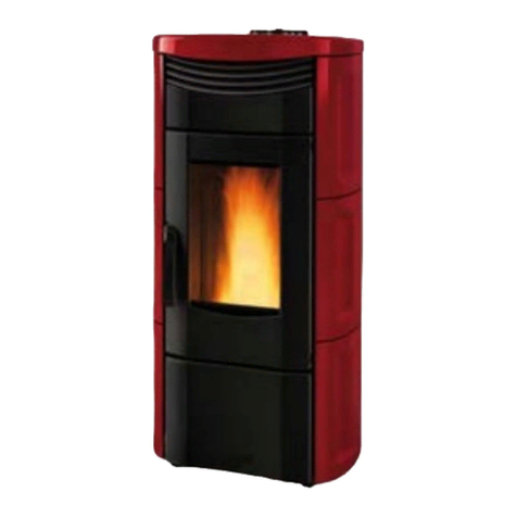
Italiana Camini PIRO Installation and operating instructions

PIRO
®
Pellet stove
UK Installation, use and maintenance

2
ENGLISH
The undersigned with head office headquarters at Via Vincenzo
Monti 47 - 20123 Milan - Italy - VAT IT00192220192
Declares under its own responsability as follows:
The pellet stove illustrated below conforms to Regulation EU
305/2011 and to the harmonised European Standard
EN 14785:2006
WOOD PELLET STOVES, trademark ITALIANA CAMINI,
called PIRO
Year of manufacture: Ref. Data nameplate
Declaration of performance (DoP - EK 131):
Ref. data tag plate
In addition, it is hereby declared that:
the wood pellet stove PIRO is in compliance with the
requirements of the European directives:
2014/35/EC - Low voltage directive
2014/30/EC - Electromagnetic compatibility directive
Safety Information 4
General information 5
Installation 7
Instructions for use 13
Maintenance 18
Possible troubleshooting 20
TABLE OF CONTENTS

3
ENGLISH
Dear Sir/Madam
Congratulations on choosing our product. Before you use it,
please read this manual carefully, to get the best from your
new appliance in total safety.
This manual is an integral part of the product.
Please keep it for the entire life of the product.
After unpacking the product, check the condition and com-
pleteness of the contents.
In the event of error, immediately contact the retailer where
the purchase was made, providing him with a copy of the
warranty booklet and the sales receipt.
The appliance must be installed and operated in compliance
with local and national law and European regulations.
For the installation, and for anything not specifically indicated
in the manual, observe local regulations.
The diagrams in this manual are illustrative; they do not al-
ways refer specifically to your product and are not binding
in any way.
MEANING OF SYMBOLS
In some parts of the manual the following symbols are
used:
INFORMATION:
failure to comply with these requirements
will compromise product use.
PLEASE NOTE:
carefully read and understand the
message in question, since failure to
follow the instructions in it could cause
serious damage to the product and put
the safety of those using it at risk.
OPERATING SEQUENCE:
follow the instructions for the operations
described
Please keep:
• the warranty certificate accompanying the product
• the purchase receipt given to you by the retailer
• the declaration of conformity given to you by the installer.
The warranty conditions are given in the warranty certificate
accompanying the product.
In Italy, commissioning by an authorised technician is re-
quired by UNI 10683, and is recommended in all countries to
ensure best results from the product.
This consists in:
• checkingtheinstallationdocuments(declarationofcon-
formity) and the quality of the installation itself;
• calibratingtheproducttosuititsactualapplication
• explanationtotheenduserandissueofcomplementary
documentation (commissioning certificate)
Having the appliance commissioned properly ensures that it
will operate to best effect and in complete safety.
Proper commissioning is required for activation of the Itali-
ana Camini warranty.
The warranty is only valid in the country of sale of the prod-
uct.
If the appliance is not commissioned by an authorised tech-
nician, Italiana Camini will not provide warranty service. See
the warranty booklet for details.
The above terms do not affect the reseller's legal responsibil-
ity for the legal warranty.
The legal warranty covers only demonstrable manufacturing
defects and not, for instance, problems resulting from im-
proper installation or calibration.

4
ENGLISH
®
SAFETY INFORMATION
• The appliance is not designed for use by people,
including children, with limited physical, sensory
and mental capacities.
• The appliance is not intended to be used for
cooking.
• The appliance is designed to burn UNI EN ISO
17225-2 category A1 wood pellets, in the amounts
and manner described in this manual.
• The appliance is designed for use indoors, in
normal conditions of ambient humidity.
• Keep the product in a dry place out of the weather.
• For the legal and company warranties, refer
to the warranty certificate inside the product:
neither Italiana Camini nor the reseller are liable
for damage resulting from incorrect installation or
maintenance.
Safety risks may be caused by:
• installation in unsuitable conditions. In particular,
conditions of fire hazard. DO NOT INSTALL THE
PRODUCT IN AREAS SUBJECT TO THE RISK OF
FIRE.
• contact with fire and hot parts (e.g. glass panel
and pipes). DO NOT TOUCH THE STOVE'S HOT
PARTS; always wear the provided gloves when
working with the stove, even if switched off, when
it is still hot. Failure do so can result in burns.
• contact with live electrical equipment (internal).
DO NOT ACCESS THE INTERNAL ELECTRICAL
EQUIPMENT WHILE THE APPLIANCE IS
POWERED ON. Electrocution hazard.
• use of improper ignition aids (e.g. alcohol). DO
NOT IGNITE OR BOOST THE FLAME WITH FLUID
SPRAYS OR A FLAME TORCH. Serious risk of
burns, damage and injury.
• use of fuel other than wood pellets. DO NOT
BURN WASTE MATTER, PLASTIC OR OTHER
MATERIALS THAN WOOD PELLETS IN THE
HEARTH. The product may be soiled, the flue may
catch fire, and environmental damage may ensue.
• cleaning the hearth when hot. DO NOT CLEAN
THE HEARTH WITH A VACUUM CLEANER WHILE
IT IS HOT. Risk of damage to the cleaner and
smoke in the room.
• cleaning the fumes duct with cleaning products. DO
NOT CLEAN THE PRODUCT WITH FLAMMABLE
PRODUCTS. Risk of fire and blowback.
• cleaning the hot glass pane with unsuitable
cleaning products. DO NOT CLEAN THE GLASS
WHILE IT IS HOT WITH WATER OR ANY OTHER
PRODUCT THAN THE RECOMMENDED GLASS
CLEANING PRODUCTS. Risk of cracking and
irreparable damage to the glass.
• storing flammable materials within the safety
clearance indicated in this manual. DO NOT
PLACE LAUNDRY ON THE PRODUCT. DO NOT
PLACE DRYING RACKS WITHIN THE SAFETY
CLEARANCE. Keep flammable fluids away from
the product. Fire hazard.
• blocking the aeration vents and air intakes in the
room. DO NOT BLOCK THE AERATION VENTS
OR FLUE. Risk of smoke returning into the room
with consequent damage and injury.
• use of the product as a support or ladder. DO NOT
CLIMB ONTO THE PRODUCT OR USE IT AS A
SUPPORT. Risk of damage and injury.
• use of the stove with the hearth open. DO NOT
USE THE PRODUCT WITH ITS DOOR OPEN.
• incandescent material projected from the open
door. DO NOT throw incandescent material
outside the appliance. Fire hazard.
• use of water in case of fire. CALL THE AUTHORITIES
IF A FIRE BREAKS OUT.
Please use all normal precautions for a household
heating appliance.
If you have doubts, please do not take any action, but
contact the retailer or the installer.
5
ENGLISH
46
Ø 4 cm aria
combustione
102
11
18
46
49
49
Ø 8 cm uscita fumi
39
6
102
46
Ø 4 cm aria
combustione
102
11
18
46
49
49
Ø 8 cm uscita fumi
39
6
102
46
Ø 4 cm aria
combustione
102
11
18
46
49
49
Ø 8 cm uscita fumi
39
6
102
46
Ø 4 cm aria
combustione
102
11
18
46
49
49
Ø 8 cm uscita fumi
39
6
102
GENERAL INFORMATION
®
DIMENSIONS (cm)
Combustion air
Ø 40 mm
Smoke outlet Ø 80 mm

6
ENGLISH
Italiana Camini reserves the right to change the products at its discretion without notice.
TECHNICAL CHARACTERISTICS according to EN 14785
The given data are indicative and taken during the certification stage at a notified Body under regulation conditions
Nominal power Reduced power
Power output 6,5 2,3 kW
Yield 90,7 93,4 %
Emissions CO 13% O20,01 0,032 %
Fume temperature 144 82 °C
Fuel consumption 1,5 0,5 kg/h
Hopper capacity 24 kg
Draught 12 10 Pa
Autonomy 14 42 hours
Heatable volume * 170 m3
Smoke outlet pipe diameter (male) 80 mm
Air intake pipe diameter (male) 40 mm
Weight including packaging 109 kg
TECHNICAL DATA FOR SIZING THE FLUE
which must anyhow meet the indications of this sheet and the installation Standards
Nominal power Reduced power
Temperatureoffumesonexitfromthedischargepipe
173 99 °C
Minimum draught 0,01 Pa
Fume flow capacity 4,8 2 g/s
GENERAL INFORMATION
* The heatable room dimensions are calculated on the basis of home insulation in compliance with Italian law
10/91,andsubsequentchangestogetherwithanexpectedheatoutputof33Kcal/m³perhour.
ELECTRICAL CHARACTERISTICS
Power supply 230 Vac +/- 10% 50 Hz
Average power consumption 50 - 80 W
Power consumption during ignition 300 W
Protection on electronic circuit board T2A,250Vac,5x20Fuse
®

7
ENGLISH
®
INSTALLATION
GENERAL NOTES
All local and National laws and the European Standards
must be met in the installation and in the use of the
equipment. In Italy it is necessary to refer to Ministerial
Decree 37/2008 (formerly Law 46/90) and the UNI
10683 Standards.
In the case of installation in a multiple-tenancy building,
contact the building manager before installation.
VERIFY COMPATIBILITY WITH OTHER
DEVICES
In Italy the stove MUST NOT be installed in the same
space or in communicating environments as type B
gas heating equipment (e.g. gas boilers, stoves, and
equipment served by an extraction hood - ref. UNI
10683 and 7129).
In general, the stove could create low pressure in the
room, affecting the operation of such appliances or
being affected by them.
VERIFYTHE POWER SUPPLY CONNECTION
(the plug must be accessible)
The stove is supplied with a power cable that is to be
connected to a 230V 50 Hz socket, preferably fitted
with a magnetothermic switch.
Voltage variations exceeding 10% can damage
the stove (unless already installed, an appropriate
differential switch must be fitted).
The electrical system must comply with the law;
particularly verify the efficiency of the earthing system.
The power line must have a suitable cross-section for
the stove’s power. An inadequate earthing system can
cause anomalies for which Italiana Camini cannot be
held liable.
One fuses (4 A) is inserted in the socket with switch,
located on the back of the stove.
AIR INTAKE (mandatory to do)
The room where the stove is located must have
an air intake with cross section of at least 80cm2
to ensurereplenishment of the air consumed by
combustion.
Alternatively, the stove air may be taken directly from
outsidethrougha4cmsteelextensionofthepipe.
POSITIONING AND DISTANCES FOR FIRE
SAFETY
The stove must be installed in compliance with the
following safety conditions:
- minimum distance from flammable materials around
the sides and back of the stove: 10 cm
- flammable materials must not be placed less than 80
cm from the front of the stove.
If it is not possible to comply with the above-mentioned
distances, technical and construction-related
provisions must be taken to prevent fire hazards.
If connected to wooden walls or other flammable
materials,thesmokeexhaustpipemustbeinsulated.

8
ENGLISH
®
46
Ø 4 cm aria
combustione
102
11
18
46
49
49
Ø 8 cm uscita fumi
39
6
102
46
Ø 4 cm aria
combustione
102
11
18
46
49
49
Ø 8 cm uscita fumi
39
6
102
INSTALLATION
SMOKE OUTLET
The stove must have its own smoke outlet (the smoke
cannot be discharged into a smoke flue used by other
devices).
The smoke is discharged through the 8 cm diameter
outlet at the back of the stove.
The smoke outlet must be connected to outside by
means of suitable steel pipes EN 1856 certified.
The pipe must be hermetically sealed.
The only horizontal section allowed may be up to 2 m
long up to three 90° bends (in relation to the vertical).
A vertical section of at least 1.5 m and an anti-wind
terminal is necessary (if the discharge outlet is not in a
chimney flue - reference UNI 10683).
Theverticalductcanbeinternalorexternal.
If the smoke channel is outside, it must be appropriately
insulated.
If the smoke channel is fitted inside a chimney flue, the
latter must be suitable for solid fuel.
If it is wider than 150 mm in diameter it must be
improved by entering a pipe that has a suitable cross-
section and is made of suitable material (e.g. 80 mm
diameter steel).
All sections of the smoke duct must be accessible for
inspection.
The chimney pots and smoke ducts connected to the
solid fuel appliances must be cleaned once a year
(verify whether a specific legislation exists in your
country).
Failure to regularly inspect and clean the stove
increases the probability of a fire occurring in the
chimney pot. In that case, proceed as follows:
Donotusewatertoextinguishthefire;Emptythepellet
hopper; Contact specialist personnel before reigniting
the stove.
The stove is designed to work under any weather
conditions. In case of particular conditions, such as
strong wind, the safety system may be activated,
whichresultsinthestovebeingextinguished.
If this happens, do not operate the stove with the safety
devices disabled.
If the problem persists, contact our Technical Service
Department.
CHIMNEY POT
The main characteristics are:
- an internal cross-section at the base, which is the
same as that of the chimney flue
- an outlet cross-section which is no smaller than twice
that of the chimney flue
- its position must be high enough to catch the wind
and avoid downdraft areas in turbulent wind, it must
be high enough to catch the wind and avoid downdraft
areas in turbulent wind.
TYPICAL EXAMPLES
FIG. 1 FIG. 2 A: flue in insulated steel compliant with EN 1856
B: minimum height of 1.5 m and in any case above the
height of the roof gutter
C-E: air intake from inside room
(minimum internal section: 80 cm²)
D:steelflue,insideexistingbrick-builtchimney.

9
ENGLISH
INSTALLATION
®
PREPARATION AND UNPACKING
Thematerialsusedinthepackagingarenottoxicor
harmful, therefore no special procedures are required
for their disposal.
Storage and disposal or recycling are the responsibi-
lity of the end user in accordance with applicable laws
PACKAGING
The package contains two pieces :
• one ( 1 ) the structure of the stove without sides
• one ( 2 ) with the top ( 3 ) and the sides ( 4 ) separate
by protection ( 5 ) and a bag with grommets to the
top
It is recommended that all vertical
movements are carried out by suitable
means and with adequate regard for
applicable safety standards.
Do not overturn the packaging and handle
all assembly parts with caution
1
2
5
3
4

10
ENGLISH
INSTALLATION
®
FITTING JACKET
Proceed as follows ( see figures ) :
• Remove the stove from the pallet , removing the
bracket and screws on both side of the stove
• Install the sides and screwing the screws on the
back
• Position the top

11
ENGLISH
INSTALLATION
®

12
ENGLISH
INSTALLATION
®

13
ENGLISH
FIG. 1
*
®
NOTE regarding the fuel.
PIRO is designed and programmed to burn wood
pellets with 6 mm diameter.
Pellets are a type of fuel in the form of little cylinders,
made from compacted sawdust, compressed under
high pressure with no adhesives or foreign materials.
They are sold in bags of 15 kg.
For the stove to function properly, you MUST NOT burn
anything else in it. Using other materials (including
wood) will render the warranty null and void. Such use
is detected by laboratory analyses. ITALIANA CAMINI
has designed, tested and programmed their stoves to
guarantee the best performance when pellets with the
following characteristics are used:
INSTRUCTIONS FOR USE
Stove are calibrated in the company in accordance
with the common conditions of installation.
Service Center, during the first lighting, check the
actual conditions, and adjust technical parameters (in
particular “chimney”) as needed.
The values of efficiency and emissions will naturally
change depending on the conditions of installation,
maintenance, and regulation of the pellets used
Service Center .
This standard indicates the control operations to be
carried out, aimed at ascertaining correct system
function.
There may be a slight smell of paint the first few times it
is ignited, however, this will disappear quickly.
Before igniting you must check:
•thatinstallationiscorrect
•thepowersupply
•thatthedoorclosesproperlytoaperfectseal
•thatthecombustionchamberisclean
•Thedisplayoftheremotecontroldisplaysstandby
status (date, power or flashing temperature).
FILLING THE PELLET HOPPER
To access the hopper, lift the lid* (fig. 1).
N.B.:
1) During this operation, the bag of pellets
MUST NEVER be placed on the upper
grill, otherwise the plastic bag, coming
into contact with the heat, could ruin the
paintwork on the top.
2) Use the special glove provided if you
load the stove while it is functioning and
therefore hot.
diameter: 6 millimetres
maximum length: 40 mm
maximum moisture content: 8%
If pellets with different characteristics are used, the
stoves must be recalibrated using a similar procedure
to that carried out by the DEALER when the stove is
ignited the first time.
Using unsuitable pellets may: decrease efficiency;
cause malfunctions; stop the stove from functioning
due to clogging, dirt on the glass, unburnt fuel, etc.
A simple, visual analysis of the pellets may be carried
out: Good quality: smooth, uniform length, not very
dusty. Poor quality: with longitudinal and transverse
cracks, very dusty, various lengths and mixed with
foreign matter.

14
ENGLISH
SYNOPTIC PANEL
INSTRUCTIONS FOR USE
key to set the desired environmental
temperature or to enter the menu
(set ambient temp.)
key for setting the power of the stove
(set power)
on/off or confirm/quit menu key
indicates that the chrono-thermostat
has been programmed for automatic
ignition at set times
indicates an alarm condition
indicates the functioning of the
pellet-loading motor
this indicates the functioning of the
fan
indicates operation of the resistance
which switches on the pellet
®
DISPLAY DESCRIPTION
M1 Set clock
M2 Set time programme
M3 Adjust vent 1
M4 (does not appear at display in
this model)
M5 Language
M6 Stand-by
M7 Screw loading
M8 Stove status
M9 Technical calibrations (TAC)
MA Type of pellets (TAC)
Mb Quit
DESCRIPTION OF MENUS
To access the menus, press and hold the
key for 2 seconds (the LED switches
off).
Press the key or the key , to scroll
through the following menus:

15
ENGLISH
INSTRUCTIONS FOR USE
®
•Toconfirmthedesiredmenu,pressthekey .
•Toreturntothepreviousmenu,pressthekey for
3 seconds.
•Toquitthemenu,pressthekey for 6 seconds.
To switch the stove on/off, press the key for 3
seconds.
LED on stove operating
stove being switched off or in
alarm state
LED off stove off
OPERATING
The stove has two operating modes:
- MANUAL
In MANUAL operating mode, the water temperature at
which the stove must operate is set independently from
the temperature of the room in which it is installed.
To select MANUAL mode, press the key (the LED
will light up).
Pressing the key will increase the temperature until
the message ‘MAN’ appears on the display (above
40°).
- AUTOMATIC
In AUTOMATIC mode, it is possible to set the desired
temperature of the room where the stove is installed.
When the desired environmental temperature (SET
ROOM TEMPERATURE) is reached, the stove will
automatically switch to power 1 mode.
To set the desired room temperature, press (the
LED turns on) and the current operating temperature
will be displayed,
By means of the key or the key, it is possible
to vary the temperature to the desired level.
Ventilation is always correlated to the power in use, so
it cannot be varied.
NOTE:
Inautomaticmode,youcanlimitthemaximumpower
setting the value , as in manual mode .
Example:ifimposedpowerP3,andthensubsequently
imposed on the stove in automatic mode, the same
will modulate P1 to P3 .
VENTILATION ADJUSTMENT
This function allows you to manage the ventilation
speed.
It can be set to AUTO mode, which automatically
adjusts the ventilation speed according to the power
of the stove, or you can set the ventilation speed
according to the amount of hot air or to the desired
noise level of the product.
To activate the function, press the key for 2
seconds and press the fkey until the display shows
the message “M3 Adjust vent 1”.
Press the key and set the desired ventilation
speed using the keys and .
To confirm your choice, press the key.
SCREW LOADING (only if the stove is
completely without pellets)
To load the screw, enter the MENU by pressing the
key for 2 seconds; then press the key until the
message “M7 first load” appears on the display.
Press the key to confirm, and then the key to
activate the function.
This operation must only be carried out when the stove
is off and completely cold.
Note:during this phase,the smoke extractorfan will
remain on.

16
ENGLISH
INSTRUCTIONS FOR USE
®
STAND-BY FUNCTION
In this mode, the stove will go off when the temperature
of the environment is 0.5°C higher than that requested,
after a set time of 10 minutes (which can be changed
by the TAC during installation).
The message “GO STBY” will appear on the display,
indicating the minutes remaining before switch-off.
This function is available in both ‘AUTOMATIC’ or
‘MANUAL’ mode and in the case of an external
thermostat.
If the environmental temperature falls to 2°C below
the set threshold, the stove will start up again (setting
modifiable by the TAC during installation).
To activate the function, press the key for about 3
seconds; the message “M1 set clock” will appear
on the display; press the key until the message
“M6 stand by” appears on the display, then con
firm by pressing the key .
Press the key to select “ON”, then confirm by
pressing the key .
To quit the menu “M6 stand by”, press the key
for about 6 seconds.
SETTING THE DATE AND TIME
Press the key for about 2 second; the message
“M1 set clock” will appear on the display; then
confirm by pressing the key .
The following data will appear in sequence: Day of the
week, hour, minutes, day, month, year; these can
be changed by pressing the key or the key .
To confirm, press the key .
To quit the menu “M1 set clock”, press the key
for about 6 seconds.
EXTERNAL THERMOSTAT
This must be connected by the blue wire (optional code
640560) to the serial port positioned on the back of
the stove; it must have a clean, normally open contact
(e.g. in the case of an environmental thermostat):
- Open contact = Environmental temperature
reached
- Closed contact = Environmental temperature not
reached
To select ‘E-T’ (external thermostat) mode,
press the key (the LED will light up).
Pressing the key will lower the temperature until
the message ‘E-T’ (external thermostat) appears on
the display (below 6°).
Note:Whenthestoveisoff,theexternalthermostat
cannot switch the stove on or off.
If you want to switch the stove on or off outside the set
time or outside the ‘E-T’ (external thermostat)
setting, you must always do so using the key
.
PROGRAMMING
There are 3 types of programming (daily, weekly,
weekend), each of which is independent of the others
and thus many combinations are possible according
to the user’s requirements (time programming is in 10
minute steps).
Press the key for 2 seconds; the message “M1
set clock” will appear on the display (and the LED
will go out).
Press the key until the message “M2 set
chrono” appears on the display; confirm by press
ing the key .
To visualise the 3 programming modes (daily, weekly,
weekend) press the key or the key , and confirm
by pressing the key .

17
ENGLISH
INSTRUCTIONS FOR USE
®
start1 06:00
stop1 08:00
start2 07:00
stop2 10:00
start3 14:00
stop3 17:00
start4 19:00
stop4 22:00
Monday on
Tuesday on
Wednesday off
Thursday on
Friday on
Saturday off
Sunday off
Monday off
Tuesday off
Wednesday on
Thursday off
Friday off
Saturday off
Sunday off
Monday on
Tuesday on
Wednesday off
Thursday off
Friday off
Saturday on
Sunday on
Monday on
Tuesday on
Wednesday on
Thursday on
Friday on
Saturday on
Sunday on
Weekly programming:
possibility of switching the stove on and off 4 times
during the day, and to choose the days of the week.
Forexample:
Weekend programming:
possibility of switching the stove on and off twice
during the weekend:
Example:
start1 week-end 07:00
stop1 week-end 11:30
Example:
start2 week-end 14:20
stop2 week-end 23:50
Scroll down the following menu (default setting is OFF):
- M2-1: enables the chrono-thermostat
- M2-2: daily programme
- M2-3: weekly programme
- M2-4: weekend programme
- M2-5: Quit
Choose the desired menu and confirm by pressing
the key .
To set the stove to switch on and off and for time
changes press the key or the key , then con
firm by pressing the key .
To quit the programme press the key for about 6
seconds.
Daily programming:
possibility of switching the stove on and off twice
throughout the day, repeated every day:

18
ENGLISH
®
Before performing any maintenance,
disconnect the appliance from the mains.
Regular maintenance is required for the stove
to function correctly.
Anyproblemsresultingfromlackofmaintenance
will immediately void the warranty.
N.B.
- Use spare parts recommended by the
manufacturer
- The use of counterfeit parts results in the
guarantee becoming null and void
DAILY MAINTENANCE
Operations must be performed when the stove
is off, cold and unplugged from the power
supply
•Cleaningmustbecarriedoutwithavacuumcleaner.
•Openthedoor,extractthefirebox(1-fig.A).
PELLET HOPPER.
•Pulltheashdraweroutandemptyitintoanon-flammable
container (the ash may still have some parts that are hot
and/or embers).
•Vacuumouttheinsideofthefirebox,firegrate,andspace
aroundthefirebox,intowhichtheashfalls.
• Remove any crust from the crucible with the spatula
provided to clear any blocked holes.
•Cleantheglass,ifnecessary(whencold).
Never vacuum hot ash, it can make the vacuum
MAINTENANCE
1
2
FIG. A
FIG. B
ATTENTION:
MAKE SURE THE ASH TRAY IS COR-
RECTLY POSITIONED IN ITS HOUSING

19
ENGLISH
®
MAINTENANCE
WEEKLY MAINTENANCE
•Removetheceiling(3-fig.C)andtiptheresidueinto
the ash drawer.
The ceiling is a component subject to wear, Italiana
Camini does not accept responsibility for it, more so
ifanybreaksareduetoextractingorputtingitbackin
its seating.
SEASONAL MAINTENANCE
(implemented by the DEALER)
Cleanthestoveinternallyandexternally
In the event of very frequent use of the
oven, it is advised cleaning of the smoke
passage duct and smoke channel every 3
months.
N.B.:
The chimneys and flue to which are connected to the
solid fuels user equipment must be cleaned once a
year (check if your country has specific legislation
covering this).
Failure to regularly check and clean increases the
likelihood of a fire in the chimney pot.
A
FIG. D
FIG. E
ATTENTION !!!
After normal cleaning, INCORRECT
D) may compromise operation of
the stove.
Before igniting the stove, make
sure the combustion chambers
are correctly paired as indicated
or unburnt material present on the
support perimeter.
We remind you that using the stove
without cleaning the melting pot,
may cause a sudden ignition gas
inside the combustion chamber
with the consequent breaking of
the glass
FIG. C
3

20
ENGLISH
In the case of problems, the stove will switch off automatically, and an indication of the
cause will appear on the display (see the various messages below).
In the case of automatic switch-off, the stove must be allowed to complete the entire
procedure (15 minutes with an acoustic signal), after which it can be restarted by pressing
the key .
However, do not restart the stove until you have found out the cause of the error and until
The stove is equipped with a safety valve, but if the routine clearing of the crucible is not
carried out as illustrated previously, there are conditions that switching on may occur with
a slight burst.
In the event of heavy and prolonged formation of white smoke within the combustion
chamber, disconnect the electrical supply and wait 30 minutes before opening the small
door and empty the crucible.
SIGNALS OF POSSIBLE CAUSES OF AN ERROR, TIPS AND SOLUTIONS:
The possible causes are listed below:
SEGNALAZIONE INCOVENIENTE AZIONI
AL1 black out
(this is not a stove
error)
(this takes place if there is no
electricity for more than 5 sec-
onds)
The stove has a ‘black out’ function. It the electricity sup-
ply is off for less than 5 seconds, the stove will switch
on again, returning to the function in progress before it
switched off.
If the electricity supply is off for more than 5 seconds, the
stove will go into ‘black out’ alarm, with consequent cool-
ing phase.
Stove status be-
fore black-out
Interruption of less than
10 seconds Interruption of more than 10 seconds
OFF OFF OFF
PRE-LOAD BLACK OUT BLACK OUT
IGNITION BLACK OUT BLACK OUT
START-UP START-UP STAND-BY THEN RE-IGNITION
OPERATING OPERATING STAND-BY THEN RE-IGNITION
FINAL CLEANING FINAL CLEANING FINAL CLEANING
STAND-BY STAND-BY STAND-BY
ALARM ALARM ALARM
ALARM RECORD ALARM RECORD ALARM RECORD
ADVICE IN CASE OF PROBLEMS
®
Table of contents
Other Italiana Camini Pellet Stove manuals
Popular Pellet Stove manuals by other brands

Qstoves
Qstoves Q 05 use and care manual

Haas+Sohn
Haas+Sohn HSP 8 CATANIA-II-RLU Installation and operating manual

Prima Heat
Prima Heat P15 Use quick instruction

Enviro
Enviro Solus owner's manual

Quadra-Fire
Quadra-Fire CB1200M-MBK Installation and operation maintenance

Quadra-Fire
Quadra-Fire SANTAFE-MBK owner's manual

AGA
AGA MK2 Operating & installation manual

Quadra-Fire
Quadra-Fire MTVERNON-AE-MBK Owner's manual & installation

vicenza
vicenza V4.5 Installation and operating instructions

Napoleon
Napoleon NPS45 Installation and operating instructions

Quadra-Fire
Quadra-Fire SANTAFE-MBK installation manual

Mareli Systems
Mareli Systems PS 10 Assembly and exploitation manual