manuals.online logo
Brands
  1. Home
  2. •
  3. Brands
  4. •
  5. ITT
  6. •
  7. Transducer
  8. •
  9. ITT GT 8 Series Instructions for use

ITT GT 8 Series Instructions for use

GT_8-IOM Rev. 0 7/19 Printed in USA
THIS INFORMATION IS SUBJECT TO THE CONTROLS OF THE EXPORT ADMINISTRATION REGULATIONS (EAR). THIS INFORMATION SHALL NOT BE PROVIDED TO
NON-US PERSONS OR TRANSFERRED BY ANY MEANS TO ANY LOCATION OUTSIDE THE UNITED STATES CONTRARY TO THE REQUIREMENTS OF THE EAR.
ITTConoflow
105 Commerce Way
Westminster, SC 29693
Tel: (864) 647-9521
Fax: (864) 647-9568
INSTRUCTION AND MAINTENANCE MANUAL
GT_8 Series Milliamp I/P Transducer
CAUTION: These instructions should be read and
understood prior to installation, use or maintenance.
GENERAL PRODUCT OVERVIEW
This I/P transducer is a force-balanced unit which uses a fixed
filtered air inlet pressure, accepts a DC milliamp input signal
and converts it to a proportional air output pressure.
Models are available with an integral relay booster (GT28,
GT48, and GT68) or without the booster (GT18, GT38, and
GT58). All models are available in FM approvals
explosionproof (XP) housings.
SPECIFICATIONS
Input Range: 4-20 or 10-50 mA DC
Nominal Impedance: 4-20 mA model: 145 ohms
10-50 mA model: 60 ohms
Output Signal: 3-15, 3-27 or 6-30 PSIG
(21-103, 21-186 or 41-207 kPa)
Required Air Supply: GT18, GT28: 25 PSIG (172 kPa)
GT38, GT48, GT58 or GT68:
35 PSIG (241 kPa)
Air Consumption: GT18, GT28: 0.20 scfm (6 slpm) max
GT38, GT48, GT58 and GT68:
0.30 scfm (8.5 slpm) max
Air Delivery Rate: GT18: 0.15 scfm (4.3 slpm) max3
GT28: 5 scfm (142 slpm) max
GT38: 0.15 scfm (4.3 slpm) max3
GT48: 5 scfm (142 slpm) max
GT58: 0.15 scfm (4.3 slpm) max3
GT68: 5 scfm (142 slpm) max
Exhaust Rate: GT18: 0.17 scfm (5 slpm) max3
GT28: 1.7 scfm (50 slpm) max
GT38: 0.2 scfm (6 slpm) max3
GT48: 2.3 scfm (65 slpm) max
GT58: 0.2 scfm (6 slpm) max3
GT68: 2.3 scfm (65 slpm) max
Linearity: +/- 1.5% of output span
Temperature Effect: 0.2% of output span / 10 °F change
For a 2 °F / minute rate of change2
Temperature Range: 0 °F to 150 °F (-18 °C to 66 °C)
Approximate Weight: Approx. 7 lb (3.2 kg) – Std. Units
Approx. 13 lb (5.9 kg) – XP Units
Piping Requirements: 3/8” Tubing or 1/4” Pipe (minimum)
NOTES:
1. A Conoflow FR95 Airpak filter regulator or equivalent
is recommended for the filtered air supply.
2. Models without a booster relay have a temperature
effect rating of approximately 0.1% of output span / 10
°F for a 2 °F / minute rate of change.
3. Low volume models (GT18, GT38, GT58) do not have
a booster relay and should only be used in low
volume flowrate applications.
Prior to installation, inspect the package and
product for damage. Do not use if damaged. Verify
operation, and calibrate the transducer using the
procedure on page 4.
INSTALLATION
See figure 1 (page 2) for location of connection interfaces
ELECTRICAL CONNECTION: The electrical connection for
the input signal is made through a ½” NPSM or ½” NPT
conduit connection on the side of the transducer housing body.
Unscrew the cover and connect the positive lead to terminal 2
and negative to terminal 1.
For reverse acting models, connect the positive lead to
terminal 1 and the negative lead to terminal 2.
WARNING
Conoflow’s products are designed and
manufactured using materials and workmanship
required to meet all applicable standards. The use
of these products should be confined to services
specified and/or recommended in the Conoflow
catalogs, instructions, or by Conoflow application
engineers.
To avoid personal injury or equipment damage
resulting from misuse or misapplication of a
product, it is necessary to select the proper
materials of construction and pressure-
temperature ratings which are consistent with
performance requirements.
Page 2 of 4 GT_8-IOM Rev. 0 7/19 Printed in USA
THIS INFORMATION IS SUBJECT TO THE CONTROLS OF THE EXPORT ADMINISTRATION REGULATIONS (EAR). THIS INFORMATION SHALL NOT BE PROVIDED TO
NON-US PERSONS OR TRANSFERRED BY ANY MEANS TO ANY LOCATION OUTSIDE THE UNITED STATES CONTRARY TO THE REQUIREMENTS OF THE EAR.
PNEUMATIC CONNECTION: Connect the supply pressure
line to the ¼” NPT inlet port (stamped “IN”). A clean, filtered
air supply (25 psi for the GT18 or GT28; 35 psi for the GT38,
GT48, GT58 or GT68 model) is required.
The 1/4” NPT output signal port delivers a pneumatic signal in
proportion to the mA DC input signal. Minimum (output) piping
requirements are 3/8” tubing or 1/4” pipe to deliver specified air
flow.
CAUTION: Teflon tape is the preferred thread sealant
for the 1/4” NPT connections. Liquid thread sealant can
migrate to the fixed orifice of the transducer and create
unreliable operation.
CAUTION: If the air supply line is connected to the
output signal port, transducer damage could occur.
Figure 1 – Interfaces and calibration / adjustment locations
Page 3 of 4 GT_8-IOM Rev. 0 7/19 Printed in USA
THIS INFORMATION IS SUBJECT TO THE CONTROLS OF THE EXPORT ADMINISTRATION REGULATIONS (EAR). THIS INFORMATION SHALL NOT BE PROVIDED TO
NON-US PERSONS OR TRANSFERRED BY ANY MEANS TO ANY LOCATION OUTSIDE THE UNITED STATES CONTRARY TO THE REQUIREMENTS OF THE EAR.
PRINCIPLE OF OPERATION
An increase in coil signal current drives the coil downward, out
of the magnet assembly, pushing the balance beam toward the
pilot nozzle. This action reduces the flow through the pilot
nozzle, increasing the backpressure.
For low volume models (GT18, GT38, or GT58), this is the
controlled output pressure.
For relay equipped models (GT28, GT48 or GT68), this
pressure above the diaphragm assembly drives the diaphragm
assembly downward, opening the relay nozzle and increasing
the output pressure. The output pressure will continue to
increase until it is equal to the pilot nozzle backpressure on top
of the diaphragm, and the forces are balanced.
A decrease in the input signal allows the coil to move into the
magnet assembly, which moves the beam away from the pilot
nozzle. This allows the flow through the nozzle to increase,
which reduces the pressure above the diaphragm assembly.
Since the output pressure is greater than the pilot nozzle
pressure, the diaphragm will move upward, allowing the relay
valve to close and the exhaust flow path to open. Air will flow
from the output side of the transducer and flow through the
relief port in the diaphragm assembly, venting to atmosphere
through exhaust holes in the diaphragm spacer. This relieving
/ exhausting action reduces the output pressure of the
transducer until equilibrium is established.
Figure 2 – Partial sectional view of transducer
Page 4 of 4 GT_8-IOM Rev. 0 7/19 Printed in USA
THIS INFORMATION IS SUBJECT TO THE CONTROLS OF THE EXPORT ADMINISTRATION REGULATIONS (EAR). THIS INFORMATION SHALL NOT BE PROVIDED TO
NON-US PERSONS OR TRANSFERRED BY ANY MEANS TO ANY LOCATION OUTSIDE THE UNITED STATES CONTRARY TO THE REQUIREMENTS OF THE EAR.
CALIBRATION AND ADJUSTMENTS
For adjustment and/or calibration verification, use the following
calibration procedure:
1. Connect the required air supply pressure (25 psig for the
GT18 and GT28, 35 psig for all others) to the inlet of the
transducer, and a pressure gauge to the outlet.
2. Connect the electrical input and set the input signal to the
0% value (e.g. 4 mA for a direct acting 4-20 mA unit).
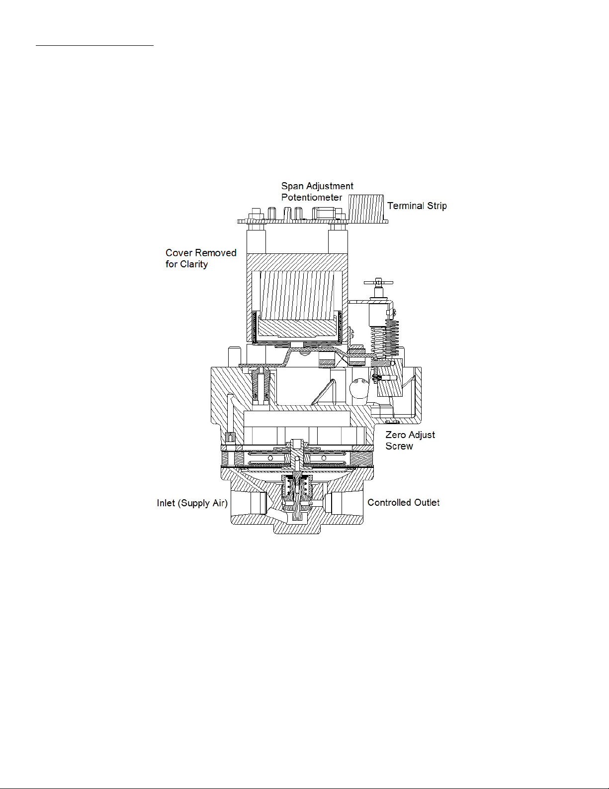
3. Observe the output pressure. Adjust if necessary by
turning the external zero adjust screw located under the
cap near the output pressure connection.
4. Increase the electrical input signal to the 100% value (e.g.
20 mA for a direct acting 4-20 mA unit).
5. Observe the output pressure. If adjustment is necessary,
remove the cover cap and adjust the range potentiometer
on the circuit board to obtain the required output.
6. The zero and range adjustments are interactive. After
adjusting the range potentiometer it will be necessary to
recheck the zero. Repeat steps 2 through 5 until both
endpoints are at the required values.
MAINTENANCE
Under normal conditions, no maintenance should be required. If
disassembly is necessary, refer to PNEUMATIC
TROUBLESHOOTING section of this document. It is important
that clean, dry air be supplied to the unit at all times. An ITT
Conoflow FR95 series Airpak (filter regulator) or equivalent
filtered air supply can be used to supply this I/P transducer
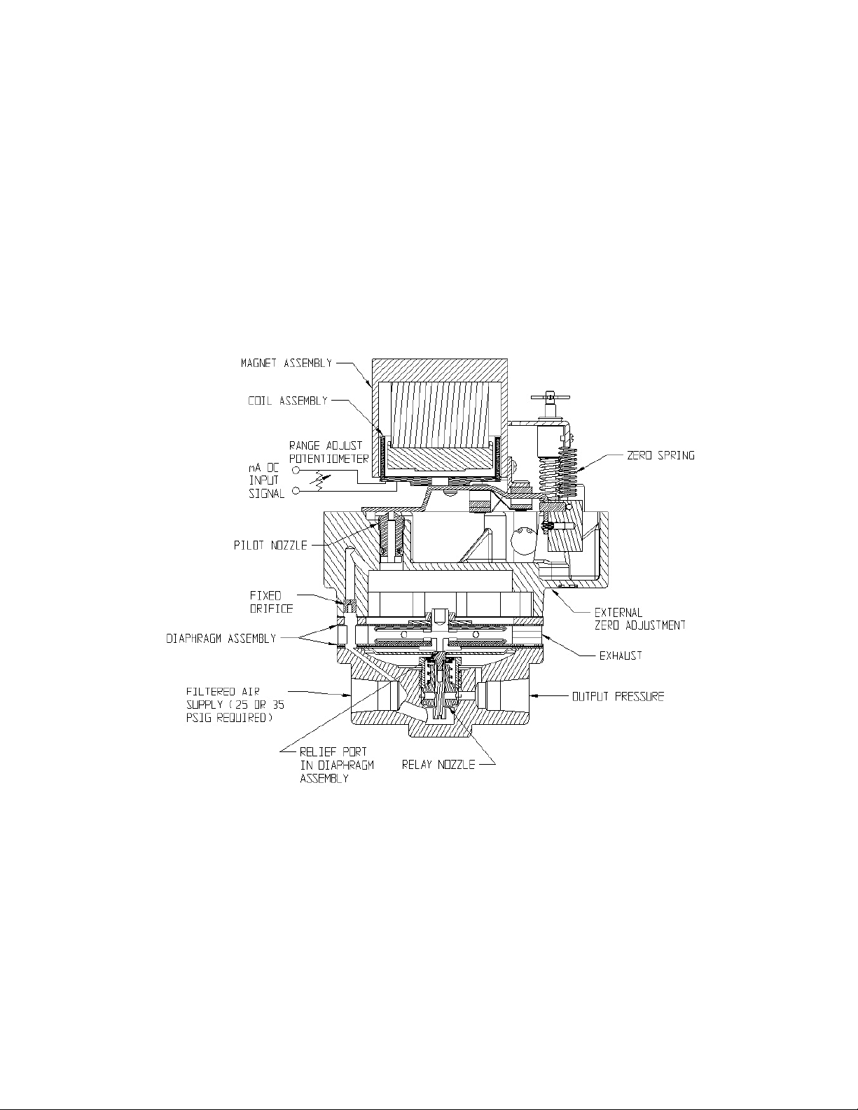
For pressure relay equipped models (GT28, GT48, or GT68)
periodically inspect the diaphragm assembly to see if the
diaphragm assembly shows signs of wear. To inspect, remove
the six (6) machine screws from the relay. While the relay is
disassembled from the I/P transducer, check freedom of
movement of the relay valve, and remove any foreign matter
which may have accumulated. When reassembling the relay, be
sure to properly orient the relay body to align the feed hole from
the inlet port to the fixed orifice in the housing cap. Tighten the
six (6) machine screws to 24 in-lb.
For replacement components, contact the factory with the full
model number and serial number of the product that parts are
required for.
TROUBLESHOOTING
PNEUMATIC
1. Check supply pressure. It should be constant 25 psig
(172 kPa) for the GT18 or GT 28 models, or a constant 35
psig (241 kPa) for all other models.
2. Make sure that tubing connections are tight.
3. Check zero and span calibration as previously outlined.
4. Check to see if housing body screen or flame arrestor (XP
version) is obstructed.
5. If disassembly is necessary, it must be done in a clean
work area. Should foreign debris become lodged between
the coil assembly and the magnet assembly, a malfunction
may occur. Removal of the magnet assembly will destroy
the calibration of the nozzle and balance beam
relationship.
6. If resonance (humming) is experienced, check outlet
piping to be sure it meets the minimum requirements
specified under INSTALLATION.
ELECTRICAL
1. Check to see that the input signal leads are connected to
proper terminals (see ELECTRICAL CONNECTION
section).
2. Make sure there are no loose wires at terminal or solder
connections.
3. Some field calibrators may not be able to supply sufficient
current to this transducer. Verify the input DC mA signal
using a digital ammeter.
4. Check input impedance by connecting an ohm meter to
terminals 1 and 2. In making any resistance tests, the
input signal wires from the controller (mA source) must be
disconnected. Nominal total input impedance of the 4-20
mA unit is 145 ohms. Nominal total input impedance of
the 10-50 mA unit is 60 ohms. Do not change the setting
of the range adjust potentiometer on the printed circuit
board when performing input impedance test.
5. A measure of resistance between any terminal of the
transducer and the external case should indicate an
“open” circuit. If resistance is indicated, coil windings or
the leads to the voice coil may be touching the case.
Further checks must then be made.
6. Remove housing from the transducer and disconnect the
coil lead plug from the circuit board. Check the
impedance of the coil. Nominal impedance is
approximately 150 ohms.
EXPLOSIONPROOF MODEL INFORMATION
FM Approvals lists the explosionproof model as
XP / I / 1 / BCD / T6 Ta = 60°C
DIP / II / 1 / EFG / T6 Ta = 60°C

Popular Transducer manuals by other brands

GE CF-LP manual

GE

GE CF-LP manual

TR-Electronic LMP-30 250 PB manual

TR-Electronic

TR-Electronic LMP-30 250 PB manual

HBK AED 9101D quick start guide

HBK

HBK AED 9101D quick start guide

Fairchild T5220 Installation, operation and maintenance instructions

Fairchild

Fairchild T5220 Installation, operation and maintenance instructions

HBM U9C Series Mounting instructions

HBM

HBM U9C Series Mounting instructions

FuehlerSysteme eNET International EM4/E operating manual

FuehlerSysteme eNET International

FuehlerSysteme eNET International EM4/E operating manual

Siemens XRS-5 Compact operating instructions

Siemens

Siemens XRS-5 Compact operating instructions

Humminbird XNT 9 20 installation guide

Humminbird

Humminbird XNT 9 20 installation guide

Simrad 38-9 - INSTALLATION REV A installation manual

Simrad

Simrad 38-9 - INSTALLATION REV A installation manual

Gossen MetraWatt SINEAX DME 4 Series operating instructions

Gossen MetraWatt

Gossen MetraWatt SINEAX DME 4 Series operating instructions

HBM U5 Series Mounting instructions

HBM

HBM U5 Series Mounting instructions

Iskra iMT416 user manual

Iskra

Iskra iMT416 user manual

CEL-MAR DES-215-PT user manual

CEL-MAR

CEL-MAR DES-215-PT user manual

FuehlerSysteme FS3160 operating manual

FuehlerSysteme

FuehlerSysteme FS3160 operating manual

S+S Regeltechnik PHOTASGARD FSHKM Operating Instructions, Mounting & Installation

S+S Regeltechnik

S+S Regeltechnik PHOTASGARD FSHKM Operating Instructions, Mounting & Installation

MKS Baratron 622A instruction manual

MKS

MKS Baratron 622A instruction manual

NITRA PNEUMATICS NCP1 Series Installation, operation and maintenance instructions

NITRA PNEUMATICS

NITRA PNEUMATICS NCP1 Series Installation, operation and maintenance instructions

Knick VariTrans P 43000 Series user manual

Knick

Knick VariTrans P 43000 Series user manual

manuals.online logo
manuals.online logoBrands
  • About & Mission
  • Contact us
  • Privacy Policy
  • Terms and Conditions

Copyright 2025 Manuals.Online. All Rights Reserved.