Installation
1. Run wire to be monitored through sensor aperture. Be sure
themonitoredcurrentowisinaccordancewithany
directional arrows on sensor.
2. Mount the transducer to a surface if needed. They can be
mounted in any position or hung directly on wires with a wire
tie. Just leave at least 30 mm distance between sensor and
other magnetic devices.
3. Connect output wiring to deadfront captive screw terminals
and observe polarity. Use up to 2.5 mm2(14 AWG) copper
wires. Tighten terminals to 0.6 Nm (5 in-lbs) torque.
- for current output models (mA), make sure output load is
no more than 500 W.
- for voltage output models (VDC), make sure output load is
at least 25 kW.
4. Connect the appropriate power supply. For optimal perfor-
mance, ensure unit has been ernergized for a period of 20
minutes prior to sensing operation.
5. Select the range that is equal to or slightly higher than the
normal operating amperage of monitored circuit. Place the
range jumper in the appropriate position.
Trouble shooting
1. Output Signal Too Low
- The jumper may be set in a range that is too high for current
being monitored. Move jumper to the correct range.
- Power supply is inadequate. Check power supply. Make
sureitisofsufcientvoltagewithallloadsatmaximum.
DK series consumes 2.0 VA.
For 0-20 mA, 4-20 mA Models
- Output load too high. Check output load, be sure it is no
more than 500 W.
For 0-5, 0-10 VDC Models
- Output load too low. Check output load, be sure it is at
least 25 kW.
2. Output Signal is always at maximum
- The jumper may be set in a range that is too low for current
being monitored. Move jumper to the correct range.
3. Sensor has not output
- Polarity is not properly matched. Check and correct wiring
polarity.
- Monitored load is not DC or is not on. Check that the
monitored load is DC and that it is actually on.
- Split Core models: The core contact area may be dirty.
Open the sensor and clean the contact area.
16September2013/Version 8
Safety and warning notes
Safe operation can only be guaranteed if the transducer is used
for the purpose it has been designed for and within the limits of
thetechnicalspecications.
Caution! Risk of danger
Ignoring the warnings can lead to serious injury and/or cause
damage!
The electric measuring transducer may only be installed and
putintooperationbyqualiedpersonnelthathavereceivedan
appropriate training.
The corresponding national regulations shall be observed during
installation and operation of the transducer and any electrical
conductor.
The transducer shall be used in electric/electronic equipment
with respect to applicable standards and safety requirements
and in accordance with all the related systems and components
manufacturers’ operating instructions.
Caution! Risk of electrical shock
When operating the transducer, certain parts of the module may
carry hazardous live voltage (e.g. primary conductor, power
supply).
The user shall ensure to take all measures necessary to protect
against electrical shock.
The transducer is a built-in device containing conducting parts
that shall not be accessible after installation.
A protective enclosure or additional insulation barrier may be
necessary.
The transducer shall not be put into operation if the jaw opening is
open (split core version) or the installation is not completed.
Installation and maintenance shall be done with the main power
supply disconnected except if there are no hazardous live parts in
or in close proximity to the system and if the applicable national
regulations are fully observed.
At the heart of power electronics
LEM is the market leader in providing innovative and high quality
solutions for measuring electrical parameters. Its core products
current and voltage transducers are used in a broad range
of applications in industrial, traction, energy, automation and
automotive markets.
For more information: www.lem.com
LEM S.A.
8, chemin des Aulx
CH-1228 Plan-les-Ouates
Switzerland
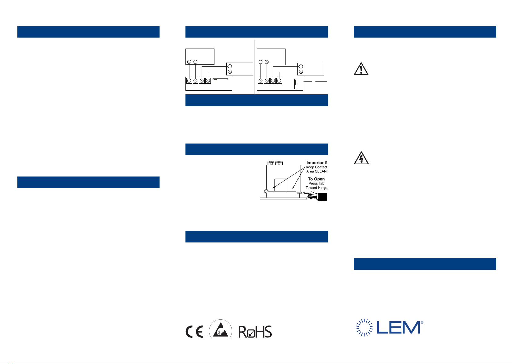
Connection diagram
DK Split core version DK Solid core version
Output polarity and primary current direction
For correct transducer mounting, please refer to the appropriate
datasheet for the respective positive current direction and transfer
characteristics of the:
- standard unipolar output version (magnitude only)
- unidirectional version (“U” option)
- bi-directional version (“B” option).
Split-core model
Press the tab in the direction as
shown to open the sensor.
After placing the wire in the
opening, press the hinged portion
rmlydownwarduntiladenite
click is heard and the tab pops
out fully.
Silicone grease is factory applied on the mating surfaces to
prevent rust and improve performance.
Be careful not to allow grit or dirst onto the grease in the contact
area. Operation can be impaired if the mating surfaces do not
have good contact. Check visually before closing.
Isolation characteristics
UbRated insulation voltage rms,
reinforced insulation, CAT III, PD2 150 V
If isolated cable is used for the primary circuit, the
voltage category could be improved according to
the following table:
Cable isolation (primary) Category
HAR 03 300 V CAT III
HAR 05 600 V CAT III
HAR 07 1000 V CAT III
UdRms voltage for AC insulation test,
50Hz, 1 min 3 kV
ULXX Plasticcaseclassication UL94-V0
1(-) 2(+) 3(-) 4(+)
Power Output
Range
Jumper High
(-) (+)
Power Supply
20-45 VDC
(+)
Load
(Controller,
Meter, Etc).
(-)
Range
Jumper Measuring
None Low
Mid Medium
High High
Mid
:
1(-) 2(+) 3(-) 4(+)
Power Output Range
Jumper
High
(-) (+)
Power Supply
20-45 VDC
(+)
Load
(Controller,
Meter, Etc).
(-)
MidLow


