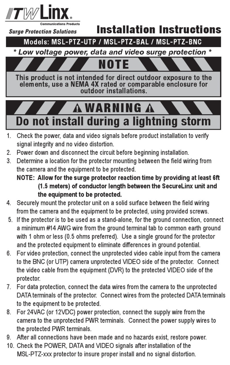
The SurgeGate series has been designed with flexibility and expansion in mind.
Additional signal line protection can easily be added with SurgeGate protection
modules.
All SurgeGate 4 units are equipped with 4 AC outlets (SurgeGate 8 KSU has 8
AC outlets) controlled by a master switch. These models also feature SurgeGate
Plus™ circuitry for over and under-voltage protection. This circuitry protects
against brownouts (under-voltages) and/or prolonged over-voltages by
automatically disconnecting the power to your equipment, then reconnecting it
when the power has returned to a safe level. This special circuitry acts as a
gate to prevent unsafe voltages from damaging your equipment:
voltage OK = power connected;
voltage unsafe = power disconnected.
In addition, all units have four diagnostic lights for maximum safety. They are
designed as follows:
1. Ground OK— (green) normally ON —
indicates that the wall outlet is properly grounded.
2. Line Fault— (red) normally OFF —
when lit, indicates that the wall outlet is improperly wired.
3. Power ON and Protection OK— (green) normally ON —
indicates that the surge protector is functioning properly, power is on, and
it is protecting all connected equipment.
4. Unsafe Voltage— (red) normally OFF —
when lit, indicates that incoming voltages are unsafe and the surge protector
has disconnected the power to protect your equipment.
If you have any questions about which product is best for your applications,
please check our web site www.itwlinx.com or contact ITW Linx Customer
Service Department at 1-800-336-LINX(5469).
1. Turn OFF the power to all equipment that will be plugged into the unit.
2. Make sure the on/off switch is in the off position (see figure 1), plug the
unit into the wall outlet, and then turn it on.
3. Once proper AC wiring and grounding has been established via a green
"Ground OK" light, unplug the unit, and plug the equipment to be
protected into the AC outlets on the unit.
4. Plug the protector in and turn it on.
5. One at a time, turn each piece of connected equipment ON and check for
power and correct operation.
6. Turn OFF the unit before installing any SurgeGate modules.
SURGEGATE M4KSU & SURGEGATE M8KSU
1. For AC connection, follow the steps in the SurgeGate 4KSU section.
2. Note the position of the LINE and EQUIP jack on the unit. LINE jack is for
the connection that comes from the wall or floor jack. EQUIP jack is for
the line connection to your connected equipment.
3. For 8COM-60 / 8COM-5x9:
Plug the incoming telephone line into the “TEL” LINE jack (up to 5 “TEL”
LINE jack included).
For 8COM-60 / 8COM-5x9:
Plug the incoming T1/LL line into the “T1/LL” LINE jack.
For 8COM-60 / 4LAN:
Plug the incoming LAN line into the “LAN” LINE jack.
4. After connect the line between the wall and the unit, now plug…
• A Phone into the “TEL” EQUIP jack or
• A LAN cord into the “LAN” EQUIP jack or
• A T1/LL cord into the “T1/LL” EQUIP jack.
Plug the other end into the equipment to be protected.
5. Turn ON the unit and all equipment. Verify that each piece of equipment is
receiving power and signal.
6. Turn OFF the unit before installing any SurgeGate modules.
SURGEGATE 4LAN, 8COM-60 & 8COM-5X9
Surges can get into your system from any metallic pathway
(wire) and from any direction. AC power lines, analog (voice)
lines, digital lines, data lines and even grounding wires can
carry a surge into your system and damage or destroy
system components. Make sure all pathways including AC,
digital, analog and data lines connected to your system pass
through the appropriate SurgeGate unit. This establishes a
common ground reference for the entire system per IEEE
recommendations. Failure to protect all lines/wires will
weaken the protection.
INCOMING
DATA
PHONE LINES
ANY OTHER
SIGNAL LINES
To properly
grounded
AC receptaccle
No other ground
AC
AC
AC
B
U
B
B
L
E
O
F
P
R
O
T
E
C
T
I
O
N
No other wires or cables attached to equipment
KSU
PROTECTED
EQUIPMENT
BUBBLE OF PROTECTION—THE BASIC CONCEPT
www.itwlinx.com Customer Service: 1-800-336-LINX (5469)
Part #: 2800-020-30I (Revision 2) 12/2009 Copyright® 2009 ITW Linx
The Power Protection indicator light is not lit, there is no AC power to my
equipment, or my equipment doesn’t turn on. What could be the problem?
• Make sure that the protector is plugged into a working AC outlet.
• Check all AC power connections.
• Make sure both the surge protector and connected equipment is turned on.
• Check to see if the circuit breaker on the surge protector needs to be
reset (press in).
FREQUENTLY ASKED QUESTIONS
The circuit breaker disconnects AC power from the connected
equipment. What could be the problem?
• You have exceeded the ampere rating for your surge protector. As a
temporary fix, disconnect one or more pieces of equipment. Call ITW
Linx Customer Service Department at 800-336-LINX for more information.
The length of any SurgeGate 4 is 9.5 inches; The length of any SurgeGate 8 is 13.5
inches. Dimensions include the mounting clips.
Hold the protector up to the wall where you want it mounted (the unit should be
mounted vertically).
1. Locate the two screw holes on the attached mounting plate (bottom of unit)
and single screw hole on the module connection plate.
EYELET
#6 SCREW
SIDE
VIEW
OF
WALL EYELET
W/SCREW
2. Using the three screw holes as a
guide, drive three screws into the
wall as shown in diagram above.
3. Slide the protector onto the screws
to rest in place.
Figure 2 Wall Mounting Instructions:
Hold wall mounting template (provided) up to the wall where
you want the protector mounted. The protector can be mounted
vertically or horizontally. Using the appropriate screw center
points as a guide, drive two screws into the wall. Be sure to
leave a 1/8 inch gap between the screw head and the wall for
the protector to hang on. Slide the protector down onto the
screws to rest in place.
SLOTS FOR
HORIZONTAL
MOUNTING
SLOTS FOR
VERTICAL
MOUNTING
Properly Connecting Your Surge Protector.
To completely protect your equipment from power surges, every wire leading into
or out of the equipment you want to protect must be connected to the appropriate
surge protector. Damaging lightning and power surges can enter your system
through any AC power or signal line (phone lines, grounding wires, coaxial cables,
modem cables, etc.) connected to your electrical equipment. The surge protector
must also be plugged into a properly wired and grounded outlet.


