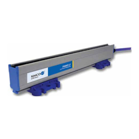
ITW Simco-Ion PINNNER User manual

Pin
ner_UM_9752
0
0
92710_NL_D_
O
C
GB_F_V2
_
1
O
plaadel
harging
NL G
e
D B
e
GB U
s
F N
o
PI
N
ektrode
s
electro
d
e
bruikersh
a
e
dienungs
a
s
er's Manu
o
tice d'utili
s
N
NE
R
s
A
d
es É
l
a
ndleiding
a
nleitung
u
al
s
ation
R
™
A
uflade-e
ectrode
s
lektrode
s
charg
e
SIMCO (Ne
d
Postbus 71
NL-7240 AB
Telefoon +
3
Telefax +
3
E-mail g
e
Internet ht
t
Traderegist
e
1
7
1
3
1
9
e
n
e
ants
d
erland) B.V.
B
Lochem
31-(0)573-28
8
3
1-(0)573-25
7
e
neral@simc
o
t
tp://www.sim
c
e
r Apeldoorn
N
3
9
8
333
7
319
o
-ion.nl
c
o-ion.nl
N
o. 08046136

Pinner_UM_9752092710_NL_D_GB_F_V2_1 1
NL
INHOUDSOPGAVE
1. Inleiding....................................................................................................................................2
2. Veiligheid .................................................................................................................................2
3. Toepassing en werking............................................................................................................2
4. Technische specificaties..........................................................................................................3
5. Installatie..................................................................................................................................3
5.1. Controle .............................................................................................................................3
5.2. Montage.............................................................................................................................3
5.2.1. Overzicht......................................................................................................................3
5.2.2. Montage algemeen ......................................................................................................3
5.2.3. Optie pinner met kop claw (zie figuur 1).......................................................................4
6. Ingebruikneming ......................................................................................................................4
7. Controle op de werking............................................................................................................5
8. Onderhoud...............................................................................................................................5
9. Storingen..................................................................................................................................5
10. Reparatie ...............................................................................................................................6
10.1. Oplaadkop vervangen......................................................................................................6
10.2. HS weerstand vervangen.................................................................................................6
10.3. HS kabel vervangen.........................................................................................................6
11. Afdanken................................................................................................................................6
12. Reserve onderdelen...............................................................................................................6

Pinner_UM_9752092710_NL_D_GB_F_V2_1 2
GEBRUIKERSHANDLEIDING PINNER ™ ELEKTRODE.
1. Inleiding
Lees deze handleiding geheel door voordat u dit product installeert en in gebruik neemt.
Instructies in deze handleiding dienen te worden opgevolgd om een goede werking van het
product te waarborgen en om aanspraak te kunnen maken op garantie.
De garantiebepalingen zijn omschreven in de Algemene Verkoopvoorwaarden van SIMCO
(Nederland) B.V.
De Pinner ™ elektrode is leverbaar met een oplaadkop met 5 punten (5 Point), met 6 punten
op een rij (lineair 6 point) en met 3 pinnen (claw).
2. Veiligheid
- De Pinner ™ elektrode is uitsluitend bestemd voor het aanbrengen van een elektrostatische
lading.
- Bij werkzaamheden aan de apparatuur: Apparatuur spanningsloos maken.
- Pinner ™ elektrode niet installeren in de directe nabijheid van brandbare materialen,
oplosmiddelen of gassen.
- Elektrische installatie en reparatie dient te geschieden door een elektrotechnisch
vakbekwaam persoon.
- Raak geen onder spanning staande punten aan.
Hierdoor krijgt u een onaangename elektrische schok.
- Metalen delen in de omgeving van de Pinner ™ elektrode, inclusief machineframe, moeten
zijn geaard.
- Indien zonder schriftelijke goedkeuring vooraf wijzigingen, aanpassingen, etc. zijn
aangebracht verliest de elektrode zijn garantie.
3. Toepassing en werking
De elektrode wordt gebruikt voor het opladen van kleine en smalle oppervlakken zoals randen,
stroken, e.d.
De elektrode vormt tezamen met een Simco-Ion d.c. hoogspanningsvoeding een Simco-Ion
"Chargemaster" elektrostatisch oplaadsysteem.
Door plaatsing van de Pinner ™ elektrode t.o.v. een geaard oppervlak ontstaat er een
elektrisch veld.
Materiaal in dit veld wordt elektrostatisch opgeladen en gaat aan het geaarde oppervlak kleven.
Wanneer zich tussen de elektrode en het geaarde oppervlak twee materialen bevinden zal het
ene materiaal neigen naar het potentiaal van de elektrode en het andere materiaal neigen naar
het aardpotentiaal, waardoor deze materialen aan elkaar gaan kleven.

Pinner_UM_9752092710_NL_D_GB_F_V2_1 3
NL
4. Technische specificaties
Werkspanning: max. 30 kV d.c.
Werkafstand: minimaal 12,5 mm bij 30 kV.
Kortsluitstroom: 375 µA bij 30 kV (HS weerstand 80 MΩ).
Gebruikstemperatuur: max. 200 °C (aan top van de elektrode).
5. Installatie
5.1. Controle
- Controleer of de elektrode onbeschadigd en in de juiste uitvoering ontvangen is.
- Controleer of de pakbongegevens overeenkomen met de gegevens van het
ontvangen product.
Bij problemen en/of onduidelijkheden:
Neem contact op met Simco-Ion of met uw agent in uw regio.
5.2. Montage
5.2.1. Overzicht
De afstand van de elektrode tot het materiaal dient proefondervindelijk te worden bepaald.
Bij een juiste afstelling moet er voldoende hechting van het materiaal zijn en mag er geen
vonkoverslag vanaf de punten optreden.
Metalen delen in de directe omgeving van de elektrode geven een verschuiving van het
elektrisch veld waardoor het oplaadeffect wordt verstoord.
De afstand van de elektrode tot metalen delen moet minimaal 75 mm bedragen
Bij vragen over montage: Neem contact op met Simco-Ion of met de agent in uw regio.
5.2.2. Montage algemeen
Waarschuwing:
-Hoogspanningskabels niet langs scherpe metalen delen leggen, niet knikken of in
scherpe bochten verleggen.
-Hoogspanningskabels gescheiden houden van laagspanningsbedrading.
- Metalen delen in de omgeving van de elektrode, inclusief machineframe, moeten zijn
geaard.
1. Monteer de 2 clips met de meegeleverde schroeven op de montagestrip.
Afstand tussen de clips minimaal 50 mm.
Voor montage van pinner claw zie 5.2.3
2. Klem de elektrode in de clips.
3. Monteer het geheel daar waar oplading wordt gewenst (afstand tot het op te laden materiaal
ca. 12,5 mm)
4. Monteer de HS kabel met de meegeleverde montageklemmen langs het machineframe naar
de d.c. hoogspanningsvoeding.

Pin
O
m
la
a
5.
5.
2
1.
2.
3.
4.
5.
6.
6.
M
e
(z
i
ner_UM_9752
0
Wa
a
m
bescha
a
tste wor
d
Sluit de
H
(zie hand
l
Steek ee
r
HV-aansl
u
2
.3. Optie
Draai
d
Druk d
e
Druk v
e
Schuif
Monte
e
Zet de
Ingebr
u
e
t het insc
i
e handlei
d
0
92710_NL_D_
a
rschuwi
n
diging va
n
d
en gem
o
H
S kabel,
m
l
eiding d.c
r
st de deel
u
iting. Ver
g
pinner m
e
d
e pinnerk
o
e
punten(
4
e
rvolgens
de teflons
c
e
r de pinn
e
punten(4)
Figuur 1.
u
iknemi
n
hakelen v
a
d
ing d.c. h
o
GB_F_V2
_
1
n
g:
n
de hoo
g
o
nteerd.
m
iddels de
. hoogspa
n
1 van de
c
g
rendel al
s
e
t kop cl
a
o
p(2) in d
e
4
) met de
v
de punten
c
hijf(3) te
g
e
r zie 5.2.
2
in de juist
e
n
g
a
n de d.c.
o
ogspanni
g
spannin
g
veerconn
e
n
ningsvoe
d
c
onnector
s
laatste d
e
a
w (zie fig
u
e
body(1).
v
lakke kan
t
zo ver m
o
g
en de pin
n
2
.
e
positie.
hoogspan
n
ngsvoedin
HV-aa
n
g
skabel te
e
ctor, aan
d
ing).
in de HV-
a
e
kabel d
o
u
ur 1)
t
door de t
o
gelijk in d
e
n
erkop(2).
n
ingsvoed
g).
n
sluiting op
d
vermijde
n
op de d.c.
a
ansluiting
or deel 3
o
eflonschijf
e
pinnerk
o
ing wordt
d
d
e d.c. hoog
s
n
moet d
e
hoogspa
n
, draai ver
v
o
p deel 2 t
e
(
3).
p(2).
d
e elektro
d
s
panningsv
o
e
el 3 van
d
n
ningsvoe
d
r
volgens d
e
e
draaien.
d
e in werki
o
eding
4
d
e wartel
a
d
ing
e
el 2 in de
ng gestel
d
a
ls
d

Pinner_UM_9752092710_NL_D_GB_F_V2_1 5
NL
7. Controle op de werking
Controle op de werking vindt plaats door controle van de hechting van het materiaal.
Verandering van de afstand van de oplaadstaaf tot het materiaal, alsmede het veranderen van
de oplaadspanning en stroom, beïnvloeden de oplading.
8. Onderhoud
Waarschuwing:
- Bij werkzaamheden aan de apparatuur: Apparatuur spanningsloos maken.
- Houdt de elektrode schoon.
- Bij vervuiling: Punten of Claws reinigen met een harde, niet metalen, borstel.
- Bij sterke vervuiling: elektrode reinigen met isopropyl alcohol.
Let op:
- Punten of Claws niet beschadigen.
- Elektrode moet geheel droog zijn voordat deze weer wordt ingeschakeld.
9. Storingen
Probleem Oorzaak Oplossing
Geen oplading Hoogspanningsvoeding
niet ingeschakeld Schakel de hoogspan-
ningsvoeding in
Hoogspanningsvoeding
defect Repareer de hoogspan-
ningsvoeding
Hoogspanningsweerstand
in elektrode defect Vervang de hoogspan-
ningsweerstand
Onderbreking in HS kabel Herstel de HS kabel
Oplading is onvoldoende Hoogspanning te laag
ingesteld Stel de hoogspanning
hoger in
Oplaadstroom niet of te
laag ingesteld Stel oplaadstroom
(hoger) in
Afstand van elektrode tot
materiaal te groot Monteer de elektrode
dichter tot het materiaal
Elektrode vervuilt Reinig de elektrode
Vonkoverslag vanaf
elektrode Hoogspanning te hoog
ingesteld Verlaag de
hoogspanning
Afstand van elektrode tot
materiaal te klein Monteer de elektrode
verder van het materiaal
Tabel 1: storingen

Pinner_UM_9752092710_NL_D_GB_F_V2_1 6
10. Reparatie
Waarschuwing:
- Reparatie dient te geschieden door een elektrotechnische vakbekwaam persoon.
- Bij werkzaamheden aan de apparatuur: Apparatuur spanningsloos maken.
10.1. Oplaadkop vervangen.
1. Oplaadkop afschroeven en vervangen.
10.2. HS weerstand vervangen.
1. Oplaadkop afschroeven.
2. Weerstand uitnemen en vervangen.
3. Oplaadkop monteren.
10.3. HS kabel vervangen.
1. Oplaadkop afschroeven.
2. Weerstand uitnemen.
3. Trekontlasting HS kabel (stelschroef) losdraaien.
4. Kabel doorschuiven.
5. Veercontact demonteren.
6. HS kabel vervangen.
7. Het geheel in tegengestelde volgorde weer monteren.
11. Afdanken
Volg bij het afdanken van het product de lokaal geldende (milieu)regels.
12. Reserve onderdelen
Artikel nr. Omschrijving
3927500110 Oplaadkop 5 Point.
6927500205 Oplaadkop lineair 6 Point
6927500600 Oplaadkop Pinner Claw
3927900025 Body compleet
9300906565 HS weerstand 80 MΩ
9146873900 Veerconnector HV 30/60 kV
8009999054 Flexibele wartel voor veerconnector
9124976171 HS kabel

Pinner_UM_9752092710_NL_D_GB_F_V2_1 7
D
INHALT
1. Einführung................................................................................................................................8
2. Sicherheit.................................................................................................................................8
3. Einsatz und Funktionsweise.....................................................................................................8
4. Technische Angaben ...............................................................................................................9
5. Installation................................................................................................................................9
5.1. Kontrolle.............................................................................................................................9
5.2. Montage.............................................................................................................................9
5.2.1. Überblick......................................................................................................................9
5.2.2. Montage.......................................................................................................................9
5.2.3. Option Pinner mit Kopfklaue (siehe Abbildung 1).......................................................10
6. Inbetriebnahme......................................................................................................................10
7. Funktionsprüfung ...................................................................................................................10
8. Wartung .................................................................................................................................11
9. Störungen ..............................................................................................................................11
10. Reparatur.............................................................................................................................12
10.1. Aufladekopf auswechseln .............................................................................................12
10.2. HS-Widerstand auswechseln.........................................................................................12
10.3. HS-Verkabelung auswechseln.......................................................................................12
11. Entsorgung...........................................................................................................................12
12. Ersatzteile............................................................................................................................12

Pinner_UM_9752092710_NL_D_GB_F_V2_1 8
BEDIENUNGSANLEITUNG FÜR DIE PINNERTM-ELEKTRODE
1. Einführung
Lesen Sie diese Anleitung vor der Installation und lnbetriebnahme dieses Produktes vollständig
durch.
Befolgen Sie die Anweisungen in dieser Anleitung, um eine richtige Funktionsweise des
Produktes sicherzustellen und irgendwelche Garantleansprüche geltend machen zu können.
Die Garantiebedingungen sind in den Allgemeinen Verkaufsbedingungen von SIMCO
(Nederland) B.V. festgelegt.
Die Pinner ™ -Elektrode ist erhältlich mit einem Aufladekopf mit 5 Spitzen, mit 6 Spitzen in
einer Reihe (linear) und mit drei Spitzen (Klaue).
2. Sicherheit
- Die Pinner ™ -Elektrode wurde ausschließlich zur Erzeugung elektrostatischer Aufladungen
entwickelt.
- Schalten Sie die Netzspannung bei der Durchführung von Arbeiten am Gerät aus.
- Bringen Sie die Pinner ™ -Elektrode nicht in der unmittelbaren Nähe von leichtentzündlichen
Materialien, Lösungsmitteln oder Gasen an.
- Elektrische Anschluß- und Reparaturarbeiten sind von elektrotechnisch fachkundigem
Personal durchzuführen.
- Berühren Sie keine spannungsführenden Spitzen.
Sie werden sonst einen unangenehmen Stromschlag empfinden.
- In der Nähe der Pinner ™ -Elektrode befindliche Metallteile, einschließlich des
Maschinenrahmens, sind zu erden.
- Wenn ohne vorhergehende schriftliche Genehmigung Änderungen, Anpassungen usw.
vorgenommen wurden, können keine Garantieansprüche geltend gemacht werden.
3. Einsatz und Funktionsweise
Die Elektrode wird zum Aufladen kleiner und schmäler Flächen (z.B. Ränder, Streifen, usw.)
verwendet.
Die Elektrode bildet gemeinsam mit einem DC-Hochspannungs-Netzteil von Simco-Ion das
elektrostatische Aufladesystem Simco-Ion-”Chargemaster".
Durch die Positionierung der Pinner ™ -Elektrode zu einer geerdeten Fläche entsteht ein
elektrisches Feld.
Das Material, das sich in diesem Feld befindet, wird elektrostatisch aufgeladen und haftet an
der geerdeten Fläche. Wenn sich zwischen der Elektrode und der geerdeten Fläche zwei
Materialien befinden, neigt sich das eine Material zum Potential der Elektrode und das andere
Material zum Erdpotential, wodurch diese Materialien verkleben.

Pinner_UM_9752092710_NL_D_GB_F_V2_1 9
D
4. Technische Angaben
Betriebsspannung: max. 30 kV Gleichstrom
Betriebsentfernung: mindestens 12,5 mm bei 30 kV
Kurzschlußstrom: 375 µA bei 30 kV (HS-Widerstand 80 MΩ)
Betriebstemperatur: max. 200°C (an der Elektrodenspitze)
5. Installation
5.1. Kontrolle
- Prüfen Sie, ob die Elektrode unbeschädigt ist und ob Sie die richtige Ausführung
erhalten haben.
- Prüfen Sie, ob die Angaben auf dem Packzettel mit den am Produkt angezeigten
Daten übereinstimmen.
Bei irgendwelchen Problemen undloder Unklarheiten können Sie sich mit Simco-Ion oder Ihrem
Regionalagenten in Verbindung setzen.
5.2. Montage
5.2.1. Überblick
Die Entfernung zwischen Elektrode und Material ist erfahrungsgemäß zu ermitteln. Bei einer
richtigen Einstellung muß eine ausreichende Materialhaftung erzielt werden und darf kein
Funkenüberschlag von den Spitzen aus auftreten.
Metallteile in unmittelbarer Elektrodennähe verursachen eine Verschiebung des elektrischen
Feldes. Hierdurch wird die Aufladewirkung gestört.
Die Elektrode muß mindestens 75 mm von Metallteilen entfernt sein.
Für irgendwelche Fragen über die richtige Montageweise wenden Sie sich bitte an Simco-Ion
oder Ihren Regionalagenten.
5.2.2. Montage
Warnung:
-Sorgen Sie dafür, daß die Hochspannungskabel nicht entlang scharfkantigen
Metallteilen und nicht mit einem scharfen Bogen verlegt werden, und daß sie nicht
knicken.
-Hochspannungskabel getrennt von Niederspannungsverkabelung halten.
-In der Nähe der Pinner TM -Elektrode befindliche Metallteile, einschließlich des
Maschinenrahmens, sind zu erden.
1. Befestigen Sie die beiden Schellen mit den mitgelieferten Schrauben am Montagestreifen.
Die Entfernung zwischen den Schellen muß mindestens 50 mm betragen.
Für die Montage der Pinnerklaue siehe Abschnitt 5.2.3.
2. Klemmen Sie die Elektrode in den Schellen fest.
3. Montieren Sie das Ganze dort, wo die Aufladung gewünscht ist (Entfernung zum
aufzuladenden Material ca. 12,5 mm).
4. Montieren Sie die HS-Verdrahtung mit den mitgelieferten Montageklemmen entlang dem
Maschinenrahmen zum DC-Hochspannungs-Netzteil.

Pin
U
m
z
u
5.
5
.
7.
8.
9.
1
0
11
1
2
6.
Di
(s
i
7.
Di
Di
s
o
ner_UM_9752
0
Wa
r
m
Schäde
u
letzt mo
n
Schließe
n
an (siehe
Stecken
S
anschlie
ß
auf Teil 2
.
2.3. Opti
o
Drehe
n
Drück
e
Drück
e
0
. Schieb
. Montie
2
. Bringe
n
Inbetri
e
e Elektrod
i
ehe die B
e
Funkti
o
e Funktio
n
e Aufladu
n
o
wie durch
0
92710_NL_D_
r
nung:
n des Ho
c
n
tiert wer
d
n
Sie das
H
Bedienun
g
S
ie zunäc
h
ß
end Teil 2
drehen.
o
n Pinner
n
Sie den
P
e
n Sie die
S
e
n Sie ans
c
en Sie die
ren Sie d
e
n
Sie die
S
A
bbildun
e
bnahm
e
e wird dur
c
e
dienungs
o
nsprüfu
n
sprüfung
e
n
g wird du
r
eine Aufl
a
GB_F_V2
_
1
c
hspannu
d
en.
H
S-Kabel
m
g
sanleitun
h
st Teil 1 d
in den H
S
mit Kopf
k
P
innerkop
f
S
pitzen (4
)
c
hließend
Teflonsc
h
e
n Pinner,
s
S
pitzen (4)
g 1.
e
c
h Einsch
a
anleitung
f
ng
e
rfolgt dur
c
r
ch eine Ä
n
a
despann
u
ngskabel
s
m
ithilfe de
s
g DC-Hoc
h
es Anschl
u
S
-
A
nschlu
s
k
laue (sie
h
f
(2) in das
)
mit der fl
a
d
ie Spitze
n
h
eibe (3) g
e
s
iehe Abs
c
in die rich
a
ltung des
f
ür das D
C
c
h eine K
o
n
derung d
e
ngs- und
S
HS-
An
s
zu verm
s
Federst
e
h
spannun
g
u
sses in d
e
s
s. Arretier
e
h
e Abbild
u
Gehäuse
a
chen Sei
t
n
so weit
w
e
gen den
P
c
hnitt 5.2.
2
tige Positi
o
DC-Hoch
s
C
-Hochspa
o
ntrolle de
s
e
r Entfern
u
S
tromänd
e
n
schluss am
eiden, m
u
ckers an
d
g
s-Netzteil
e
n HS-
A
n
s
e
n Sie zul
e
u
ng 1)
(1).
t
e durch di
w
ie möglic
h
P
innerkop
f
2
.
o
n.
s
pannung
s
nnungs-N
e
s
Material
s
u
ng zwisc
h
e
rung, bee
DC-Hochs
p
u
ss Teil 3
d
d
as DC-Ho
).
s
chluss un
d
e
tzt das K
a
e
Teflons
c
h
in den Pi
f
(2).
s
-Netzteils
e
tzteil).
s
auf ordn
u
h
en Auflad
i
nflußt.
annungs-N
e
der Über
w
o
chspannu
d drehen
S
a
bel, inde
m
c
heibe (3).
i
nnerkopf
(
in Betrieb
u
ngsgemä
ß
d
estab und
e
tzteil
10
w
urfmutte
r
n
gs-Netzt
e
S
ie
m
Sie Teil
3
(
2).
gesetzt
ß
e Haftun
g
Material,
r
e
il
3
g
.

Pinner_UM_9752092710_NL_D_GB_F_V2_1 11
D
8. Wartung
Warnung:
- Schalten Sie die Netzspannung bei der Durchführung von Arbeiten am Gerät aus.
- Halten Sie die Elektrode sauber.
- Bei Verschmutzung: Reinigen Sie die Spitzen oder die Klaue mit einer harten (Nichtmetall-)
Bürste.
- Bei starker Verschmutzung: Reinigen Sie die Elektrode mit lsopropylalkohol.
Achtung:
- Sorgen Sie dafür, daß Sie die Spitzen oder die Klaue nicht beschädigen.
- Die Elektrode muß vor der Wiedereinschaltung ganz trocken sein.
9. Störungen
Problem Ursache Abhilfe
Keine Aufladung Hochspannungs-Netzteil
nicht eingeschaltet Hochspannungs-Netzteil
einschalten
Defektes Hochspannungs-
Netzteil Hochspannungs-Netzteil
ausbessern
Defekter Hochspan-
nungswiderstand in
Elektrode
Hochspannungswiderstand
auswechseln
Unterbrechung in der HS-
Verdrahtung HS-Verdrahtung
ausbessern
Aufladung unzureichend Hochspannung zu niedrig
eingestellt Hochspannung höher
einstellen
Aufladestrom nicht oder zu
niedrig eingestellt Aufladestrom (höher)
einstellen
Entfernung zwischen
Elektrode und Material zu
groß
Elektrode näher zum
Material montieren
Elektrode verschmutzt Reinigen Sie die Elektrode
Funkenüberschlag von der
Elektrode aus Hochspannung zu hoch
eingestellt Hochspannung senken
Entfernung zwischen
Elektrode und Material zu
gering
Elektrode in einer größeren
Entfernung vom Material
montieren
Tabelle 1: Störungen

Pinner_UM_9752092710_NL_D_GB_F_V2_1 12
10. Reparatur
Warnung:
- Reparaturarbeiten sind von elektrotechnisch fachkundigem Personal durchzuführen.
- Schalten Sie die Netzspannung bei der Durchf ührung von Arbeiten am Gerät aus.
10.1. Aufladekopf auswechseln
Aufladekopf abschrauben und auswechseln.
10.2. HS-Widerstand auswechseln
1. Aufladekopf abschrauben.
2. Widerstand herausnehmen und auswechseln.
3. Aufladekopf einbauen.
10.3. HS-Verkabelung auswechseln
1. Aufladekopf abschrauben.
2. Widerstand herausnehmen.
3. Stellschraube der Zugentlastung der HS-Verkabelung lösen.
4. Verkabelung weiterschieben.
5. Federkontakt ausbauen.
6. HS-Verkabelung auswechseln.
7. Das Ganze in entgegengesetzter Reihenfolge wieder einbauen.
11. Entsorgung
Das Produkt ist gemäß den örtlich geltenden (Umwelt)regeln zu entsorgen.
12. Ersatzteile
Artikel-Nr. Beschreibung
3927500110 5-Punkt-Aufladekopf
6927500205 Aufladekopf linear 6 Spitzen
6927500600 Kopf Pinner Klaue
3927900025 Gehäuse Komplett
9300906565 HS-Widerstand 80 MΩ
9146873900 Federstecker HS 30/60 kV
8009999054 Flexible Überwurfmutter für Federstecker
9124976171 HS-Verkabelung

Pinner_UM_9752092710_NL_D_GB_F_V2_1 13
GB
CONTENTS
1. Introduction............................................................................................................................14
2. Safety.....................................................................................................................................14
3. Use and operation..................................................................................................................14
4. Technical specifications.........................................................................................................15
5. Installation..............................................................................................................................15
5.1. Checks.............................................................................................................................15
5.2. Installation........................................................................................................................15
5.2.1. Summary....................................................................................................................15
5.2.2. Installation..................................................................................................................15
5.2.3. Pinner with head claw option (see Figure 1) ..............................................................16
6. Putting into use......................................................................................................................16
7. Functional check....................................................................................................................17
8. Maintenance ..........................................................................................................................17
9. Faults.....................................................................................................................................17
10. Repair ..................................................................................................................................18
10.1. Replacing the charging head .........................................................................................18
10.2. Replacing the HV resistor ..............................................................................................18
10.3. Replacing the HV cable..................................................................................................18
11. Disposal...............................................................................................................................18
12. Spare parts ..........................................................................................................................18

Pinner_UM_9752092710_NL_D_GB_F_V2_1 14
USER'S MANUAL FOR PINNER ™ ELECTRODE
1. Introduction
Read this manual completely before you install and put this product into use.
Follow the instructions set out in this manual to ensure proper operation of the product and to
be able to invoke guarantee.
The guarantee terms are stated in the General Conditions for the Sale and Delivery of Products
and/or Performance of Activities by SIMCO (Nederland) B.V.
The Pinner ™ electrode is available with a 5-point charging head and a blade, with 6 points in a
row (linear 6 point) and with 3 pins (claw).
2. Safety
- Pinner ™ electrodes are intended only for applying electrostatic charges.
- When carrying out work on the equipment: de-energise the equipment.
- Do not install Pinner ™ electrodes in the immediate vicinity of flammable materials,
solvents or gases.
- Electrical installation and repairs shall be made by a skilled electrical engineer.
- Do nor touch any live points.
You will get an unpleasant electrical shock.
- Metal parts near the Pinner ™ electrode, including the machine frame, must be earthed.
- If changes, adjustments, etc. have been made without prior consent in writing, guarantee can
no longer be invoked for the electrode.
3. Use and operation
The electrode is used for charging small and narrow areas, such as rims, strips, etc.
In combination with a Simco-Ion DC high voltage power unit the electrode constitutes a Simco-
Ion "Chargemaster" electrostatic generating system.
An electric field is created when the Pinner ™ electrode is positioned towards an earthed
surface.
Material in this field is charged electrostatically and will adhere to the earthed surface. When
two materials are placed between the electrode and the earthed surface, one of these materials
will tend towards the potential of the electrode and the other towards the earth potential,
causing adhesion between these materials.

Pinner_UM_9752092710_NL_D_GB_F_V2_1 15
GB
4. Technical specifications
Operating voltage: 30 kV DC max.
Operating distance: 12.5 mm minimum at 30 kV.
Short-circuit current: 375 µA at 30 kV (HV resistance 80 MΩ).
Operating temperature: 200°C max. (at the top of the electrode).
5. Installation
5.1. Checks
- Check that the electrode is undamaged and that you have received the correct version.
- Check that the data on the packing slip corresponds with the data shown on the product
received.
If you have any problems andlor in the case of ambiguity.
please contact Simco-Ion or your regional agent.
5.2. Installation
5.2.1. Summary
The distance from the electrode to the material should be established by experiment. When
adjusted properly, there should be sufficient bonding of the material and no spark-over from the
points must occur.
Metal parts in the immediate vicinity of the electrode cause a shift in the electric field. As a
result, the charging effect is disrupted. The minimum distance between electrode and metal
parts must be 75 mm.
If you have any questions concerning the installation:
please contact Simco-Ion or your regional agent.
5.2.2. Installation
Warning:
-Do not lay high voltage cables along sharp metal parts or in sharp bends and do not
kink them.
-Keep high-voltage cables separated from low-voltage wiring.
-Metal parts near the electrode, including the machine frame, must be earthed.
1. Using the screws supplied, fit the 2 clips to the mounting strip.
Minimum distance between the clips 50 mm.
2. Clamp the electrode in the clips
3. Mount the unit in the place where charging is required (keeping it at a distance of
approx. 12.5 mm from the material to be charged).
4. Using the assembly clamps supplied, fix the HV cable alongside the machine frame to the
DC high voltage power unit.

Pin
In
m
5.
5.
2
1.
2.
3.
4.
5.
6.
6.
T
h
m
a
ner_UM_9752
0
Wa
r
order to
p
o
unted la
s
Using the
manual D
First, ins
e
the high-
v
2
.3. Pinn
e
Screw th
e
Push the
Then pus
h
Push the
Fit the pi
n
Position t
h
Putting
h
e electro
d
a
nual of t
h
0
92710_NL_D_
r
ning:
p
revent d
a
s
t.
spring co
n
C high vol
e
rt part 1 o
f
v
oltage co
n
e
r with he
a
e
pinner h
e
points (4)
w
h the poin
t
Teflon dis
k
n
ner (see
5
h
e points
(
Figure 1.
into us
e
d
e is put in
t
h
e DC high
GB_F_V2
_
1
a
mage to
n
nector, c
o
tage pow
e
f
the conn
e
n
nector. Fi
a
d claw o
p
e
ad (2) int
o
w
ith the fl
a
t
s as far a
s
k
(3) agai
n
5
.2.2).
(
4) correctl
e
t
o by swit
c
voltage p
o
the high-
v
o
nnect the
e
r unit).
e
ctor in th
e
nally, lock
p
tion (see
o
the body
a
t edge th
r
s
possible
n
st the pin
n
y.
c
hing on th
o
wer unit).
High-voltag
v
oltage c
a
HV cable
s
e
high-volt
a
the cable
Figure 1)
(1).
r
ough the
T
into the pi
n
n
er head (
2
e DC high
.
e connectio
n
a
ble, part
3
s
to the D
C
a
ge conn
e
by screwi
n
T
eflon dis
k
n
ner head
2
).
voltage p
o
n
to the DC
h
3
of the g
l
C
high volt
a
ctor, and t
n
g part 3 t
o
k
(3).
(2).
o
wer unit (
h
igh voltage
l
and sho
u
a
ge powe
r
t
hen twist
p
o
part 2.
(
please re
f
power unit
16
u
ld be
r
unit (see
p
art 2 into
f
er to the

Pinner_UM_9752092710_NL_D_GB_F_V2_1 17
GB
7. Functional check
The proper functioning is established by checking the material bonding.
Charging is affected by changes in the distance from charging bar to material as well as by
charging voltage and current changes.
8. Maintenance
Warning:
- When carrying out work on the equipment: de-energise the equipment.
- Keep the electrode clean.
- If fouled: Clean the points or blade with a hard non-metal brush.
- If heavily fouled: Clean the electrode with isopropyl alcohol.
Attention:
- Do not damage the points or blade.
- Make sure the electrode is entirely dry before you turn it on again.
9. Faults
Problem Cause Remedy
No charging High voltage power unit not
switched on Switch on the high voltage
power unit
High voltage power unit
defective Repair the high voltage power
unit
Defective high voltage resistor
in electrode Replace high voltage resistor
HV cable interrupted Restore HV cable
Insufficient charging High voltage set too low Raise high voltage
Charging current not set or set
too low Set (or raise) charging current
Distance from electrode to
material too large Mount the electrode closer to
the material
Electrode fouled Clean the electrode
Spark-over from electrode High voltage set too high Reduce high voltage
Distance from electrode to
material too small Mount the electrode farther
away from the material
Table 1: faults

Pinner_UM_9752092710_NL_D_GB_F_V2_1 18
10. Repair
Warning:
- Repairs shall be made by a skilled electrical engineer.
- When carrying out work on the equipment: de-energise the equipment.
10.1. Replacing the charging head
Unscrew and replace the charging head.
10.2. Replacing the HV resistor
1. Unscrew the charging head.
2. Remove and replace the resistor.
3. Mount the charging head.
10.3. Replacing the HV cable
1. Unscrew the charging head.
2. Remove the resistor.
3. Loosen the adjusting screw of the HV cable pull relief.
4. Slide the cable through.
5. Remove the spring contact.
6. Replace the HV cable.
7. Reassemble the unit in reverse order.
11. Disposal
Adhere to the applicable local environmental and other rules when disposing of the product.
12. Spare parts
Item No. Description
3927500110 5-point charging head
6927500205 Linear 6-point charging head
6927500600 Pinner claw head
3927900025 Body complete
9300906565 80 MΩHV resistor
9146873900 Spring connector HV 30/60 kV
8009999054 Flexible gland for spring connector
9124976171 HV cable

Pinner_UM_9752092710_NL_D_GB_F_V2_1 19
F
SOMMAIRE
1. Introduction............................................................................................................................20
2. Sécurité..................................................................................................................................20
3. Application et fonctionnement................................................................................................20
4. Spécifications techniques.......................................................................................................21
5. Installation..............................................................................................................................21
5.1. Contrôle ...........................................................................................................................21
5.2. Montage...........................................................................................................................21
5.2.1. Aperçu........................................................................................................................21
5.2.2. Montage.....................................................................................................................21
5.2.3. Option électrode avec tête à griffe (voir figure 1) .......................................................22
6. Mise en service......................................................................................................................22
7. Contrôle du fonctionnement...................................................................................................22
8. Entretien.................................................................................................................................23
9.Pannes....................................................................................................................................23
10. Réparation ...........................................................................................................................24
10.1. Remplacement de la tête changeante............................................................................24
10.2. Remplacement de la résistance HT...............................................................................24
10.3. Remplacement du câble HT...........................................................................................24
11. Mise au rebut .......................................................................................................................24
12. Pièces de rechange .............................................................................................................24
Table of contents
Languages:
Other ITW Industrial Electrical manuals
Popular Industrial Electrical manuals by other brands

Murata
Murata GRM0335C1E680JA01 Series Reference sheet

Murata
Murata ZRB157R61A225KE11 Series Reference sheet

Murata
Murata GRM1555C1H6R1BA01 Series Reference sheet

Furukawa electric
Furukawa electric S153 Ver.2 user manual

Murata
Murata GRM033C80J183KE01 Series Reference sheet

Dwyer Instruments
Dwyer Instruments MTL7700 Series instruction manual