IVT Greenline HT PlusC User manual

Greenline HT Plus
C and E
User Guide
Art. no: 290410-9 Version: 1.0
FOR THE USER
INDEX

3
Manual for Heat pump Greenline HT Plus C and E
IVT Industrier AB, 2004-06-27
Article number: 290410-9
Version 1.0
Copyright © 2004. IVT Industrier AB. All rights reserved.
This manual contains copyright protected information that is the property of IVT Industrier AB. No part of this document may be copied or forwarded, electronically or mechanically,
without prior, written permission from IVT Industrier AB. This includes photographing and translation to another language.
Thank you for choosing a heat pump from
IVT Industrier
We hope that our heat pump meets your expectations and gives you many years of energy saving. We want you and
your family to enjoy a good economy at the same time as you actively safeguard the environment. We have taken today’s
demands on heat pumps into consideration and believe that your Greenline HT Plus will give you many useful functions in
the future. Your heat pump features an advanced control unit that monitors and controls the temperature in the house and
contributes towards improved overall economy. The heat pump Greenline HT Plus has, for example, a holiday function,
that's to say the heat pump can be set at a “low level” while you are away on holiday.
IVT is the leading heat pump manufacturer in the Nordic Countries. More than every second heat pump comes from IVT.
We have worked with solutions to reduce energy consumption on the environment’s terms for more than 30 years. Today
we can present the widest range of heat pumps for efficient energy saving in all types of housing and properties.
Johnny Wärnelöv
Managing director IVT Industrier AB

4
Contents
FOR THE USER .................................................................................................... 5
Important information....................................................................................... 5
This is how your heat pump works ..................................................................... 6
Technology in and around the heat pump................................................................................................................6
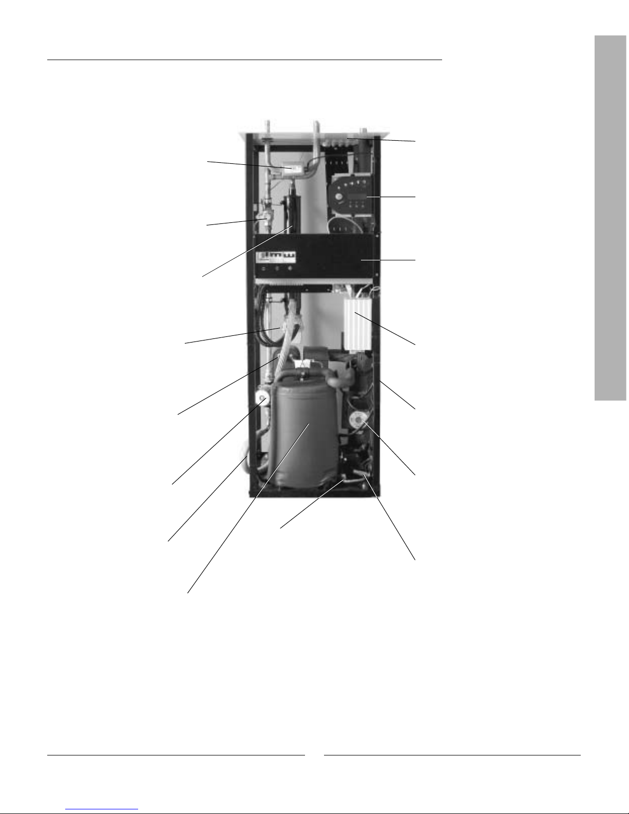
Component parts of the heat pump .................................................................... 8
Control unit Rego 637..................................................................................... 10
The control unit’s two methods to control the heat pump........................................................................................11
The control panel ............................................................................................ 12
Buttons and lamps ................................................................................................................................................12
Menu dial .............................................................................................................................................................13
How to use the control panel .................................................................................................................................13
Basic functions (Customer level 1) ................................................................... 13
Menu outline for Basic functions (Customer level 1).............................................................................................14
Select scrolling information on the menu display...................................................................................................14
Set the heating ......................................................................................................................................................15
Set the desired room temperature ..........................................................................................................................18
Set the heat pump for extra hot water ....................................................................................................................18
Heating and hot water settings ..............................................................................................................................19
Read the temperatures on the heat pump...............................................................................................................19
Extra functions (Customer level 2) ................................................................... 21
Menu outline for Extra functions (Customer level 2).............................................................................................21
Temperature settings ............................................................................................................................................22
Set extra heat curve with mixing valve ..................................................................................................................23
Hot water settings .................................................................................................................................................24
Timer control........................................................................................................................................................24
Reading operating times on the heat pump and additional heat ............................................................................25
Set the time and date ............................................................................................................................................26
Alarms given by the heat pump .............................................................................................................................27
Return to factory settings.......................................................................................................................................27
Maintenance................................................................................................... 28
Opening the front cover .........................................................................................................................................28
Sight glass.............................................................................................................................................................28
Expansion vessel ...................................................................................................................................................29
Particle filter.........................................................................................................................................................29
Checking the protective anode ...............................................................................................................................30
Savings .......................................................................................................... 31
What to do if a fault occurs .............................................................................. 32
Dimmed menu display ..........................................................................................................................................32
Fuses and reset buttons on the heat pump..............................................................................................................33
All alarms.............................................................................................................................................................33
Technical information...................................................................................... 40
The heat pump's factory settings ............................................................................................................................40
Sensor table...........................................................................................................................................................40
Technical information...........................................................................................................................................41
Index ............................................................................................................. 42
Table of Contents

5
Note
It is important as the user that you
read through this chapter.
Under no circumstances may the user
make settings that are designed for
the installer. This can cause serious
malfunction of the heat pump.
Important information
The heat pump Greenline HT Plus represents a new generation of heat
pumps from IVT Industrier. It contains numerous functions to control the
temperature and production of hot water in the house. The control unit
Rego 637 is the brains of the heat pump. Rego 637 includes a control and
monitoring function that stores important settings about the heat pump's
operation and maintenance. The settings are made by the installer and the
user via a control panel on the front of the heat pump. Settings intended
for the user, are presented under the headings Basic functions and Extra
functions.
When the heat pump has been installed and started there are a number of
points you should check regularly. This may concern an alarm triggering
or performing basic maintenance actions. First of all you should perform
these actions yourself. This manual describes each step in detail. If the
problem remains you should contact your dealer.
For the user

6
FOR THE USER
This is how your heat pump works
The heat pump Greenline HT Plus represents a new generation of heat pumps from IVT Industrier. The heat pump has
been manufactured for easy and reliable use as well as to provide your house with inexpensive and environment friendly
heating. The easiest way to describe how a heat pump works is to say it works like a refrigerator, however, the other way
round. In a refrigerator heat is moved from the inside to the outside. In a heat pump heat stored in the ground, rock or
water, is moved into the house. The heat pump collects a few degrees of the stored solar energy. The heat is led into the
house via a hose. The temperature is then increased in the heat pump and the heat is distributed to the house’s heating
system.
The heat pump collects stored solar energy
Boiling point in relation to the
pressure:
The boiling point of different liquids
varies with pressure, the higher the
pressure, the higher the boiling point.
For example, water boils at +100ºC
at normal pressure. Double the pres-
sure and water boils at +120ºC. Half
the pressure and water then boils at
+80ºC. The refrigerant in the heat
pump acts in the same way, the boiling
point changes when the pressure
changes. However, the boiling point of
the refrigerant is as low as approxima-
tely -40ºC at atmospheric pressure.
Consequently, it is also suitable for
low heat source temperatures.
Note
Rock heat Soil heat Lake heat
The heat pump consists of four main parts:
1. Evaporator
Evaporates the refrigerant to gas and at the same time transfers the
heat from the heat transfer fluid to the refrigerant circuit.
2. Condenser
Condenses the gas to fluid again and transfers the heat to the heating
system.
3. Expansion valve
Lowers the pressure of the refrigerant.
4. Compressor
Increases the pressure of the refrigerant.
These four main parts are linked in three circuits. A refrigerant circulates
in the heat pump, which in some parts of the circuit is in a liquid state and
in other parts in a gas state. Read more about the properties of the refrige-
rant in the sidebar to the right.
See the detailed description of the technologies used in the heat pump on
the next page.
Technology in and around the heat pump
This is how your heat pump works

7
FOR THE USER
Heat transfer fluid in. A hose is connected here that collects the stored solar energy from, e.g., the soil or
rock. The hose contains a heat transfer fluid, which is a mixture of water and anti-freeze. The fluid collects
the heat from the rock and with the help of the HTF pump leads it into the heat pump and the evaporator. The
temperature is then approximately 0ºC.
In the evaporator the heat transfer fluid meets the refrigerant. At this stage the refrigerant is in a fluid state
and is at approximately -10ºC. When the refrigerant meets the zero degree heat transfer fluid it starts to boil.
It then forms a vapour, which is led into the compressor. The temperature of the vapour is 0ºC.
The pressure of the refrigerant increases in the compressor and the vapour temperature rises from 0ºC to
approximately +100ºC. The warm gas is then forced into the condenser.
The condenser is the heat pump's heat emitting part. Here the heat is transferred to the house’s heating
system (radiators and floor heating) and the hot water system. The vapour is cooled in the condenser and
becomes fluid. The pressure in the refrigerant is still high when it is led on to the expansion valve.
The refrigerant pressure is then lowered in the expansion valve. At the same time, the temperature also drops
to approximately -10ºC. When the refrigerant has passed through the valve and the evaporator it changes to
vapour again.
In heat transfer fluid out, the heat transfer fluid is led out from the heat pump to the rock to collect new stored
solar energy. The temperature of the fluid is approximately -3ºC.
1
2
3
4
5
6
Floor heating
Radiator
Fan-assisted
radiator
Heat pump
Rock
Soil
0ºC
-3ºC
0ºC +100ºC
+65ºC
+57ºC
-10ºC
1
6
2 3 4
5Heat carrier pump
Heat
transfer pump
This is how your heat pump works
"The hot side"
"The cold side"

8
FOR THE USER
Component parts of the heat pump
Three-way valve
The valve switches between
heating the heating water and hot
water.
Hot water heater
The cylinder is double-shelled
and holds approximately 165 litres
of hot water and 60 litres of the
heating water.
Electric cassette
The electric cassette is used
to provide extra output in cold
weather conditions, with large
water consumption and at hot
water peaks.
Reset button
Press in the button if the overheat
protector on the electric cassette
has tripped. The button is located
on the side.
Heat carrier pump
The pump ensures the heating
water circulates within the heating
system.
Compressor
The compressor increases the
pressure of the refrigerant.
The temperature of the vapour
increases from 0ºC to approxima-
tely +100ºC. The compressor is
insulated to decrease the noise
level.
Socket
Connections for the mains supply
as well as sensors.
Control panel
The control panel has a back-
ground lit menu display with four
rows of text information, three
buttons and a dial.
Distribution box
The distribution box is enclosed.
It houses a reset function for the
motor cut-out as well as miniature
circuit-breakers (MCB) for the
heat pump and electric cassette.
Heat transfer fluid pump
The pump is insulated and
features an anti-corrosive finish.
It ensures the heat transfer fluid
circulates from, e.g. the rock to
the heat pump.
Control unit Rego 637
The control unit is enclosed. It
controls and monitors all heat
pump functions.
Expansion valve
Lowers the pressure of the
refrigerant that is to enter the
evaporator and collect energy
from, e.g. the rock.
Sight glass
Sight glass to check the level in the
refrigerant circuit. Air bubbles must not
form in the sight glass when the heat
pump is running. However, there might
be bubbles when the heat pump is started
and stopped.
Flexible hoses
The hoses counteract vibrations in
the heat pump.
IVT Greenline HT Plus C
Evaporator
The evaporator evaporates the
refrigerant to gas and transfers
heat from the heat transfer fluid to
the refrigerant circuit (behind the
heat pump).
Condenser
The condenser condenses the
vapour to fluid again and transfers
the heat to the heating system.
Component parts of the heat pump

9
FOR THE USER
IVT Greenline HT Plus E
Reset button
Press in the button if the overheat
protector on the electric cassette
has tripped. The button is located
on the side.
Heat carrier pump
The pump ensures the heating
water circulates within the heating
system.
Compressor
The compressor increases the
pressure of the refrigerant.
The temperature of the vapour
increases from 0ºC to approxima-
tely +100ºC. The compressor is
insulated to decrease the noise
level.
Socket
Connections for the mains supply
as well as sensors.
Control panel
The control panel has a back-
ground lit menu display with four
rows of text information, three
buttons and a dial.
Distribution box
The distribution box is enclosed.
It houses a reset function for the
motor cut-out as well as miniature
circuit-breakers (MCB) for the
heat pump and electric cassette.
Heat transfer fluid pump
The pump is insulated and features
an anti-corrosive finish. It ensures
the heat transfer fluid circulates
from, e.g. the rock into the heat
pump.
Control unit Rego 637
The control unit is enclosed. It
controls and monitors all heat
pump functions.
Expansion valve
Lowers the pressure of the refrige-
rant that is to enter the evaporator
and collect energy from, e.g. the
rock.
Sight glass
Sight glass to check the level in the
refrigerant circuit. Air bubbles must
not form in the sight glass when the
heat pump is running. However, there
might be bubbles when the heat
pump is started and stopped.
Flexible hoses
The hoses counteract
vibrations in the heat pump.
Evaporator
The evaporator evaporates the
refrigerant to gas and transfers
heat from the heat transfer fluid to
the refrigerant circuit (behind the
heat pump).
Particle filter
The filter can be opened for easy
cleaning. It also has a shut off
function.
Electric cassette
The electric cassette is used
to provide extra output in cold
weather conditions, with large
water consumption and at hot
water peaks.
Three-way valve
The valve switches between
heating the heating water and hot
water.
Condenser
The condenser condenses the
vapour to fluid again and transfers
the heat to the heating system.
Component parts of the heat pump

10
FOR THE USER
Control unit Rego 637
The control unit Rego 637 is the brains of the heat pump. It makes sure the
heat pump gives the best energy savings and that it runs for many years.
The control unit controls and monitors the heating and hot water supply in
your house. The monitoring function is especially important. It shuts down
the heat pump in the event of operational disturbances so that no critical
parts are damaged.
Additional heat gives more output
When the heat pump can not manage to heat the house by itself, for
example, if there is a considerable drop in the outdoor temperature, the
control unit ensures the additional heat source is connected. Together
the heat pump and additional heat guarantee the right temperature in the
house. Additional heat in the Greenline HT Plus is provided by a built
in electric cassette. Additional heat can never completely take over the
heating from the heat pump. It only adds the output necessary for the heat
pump to be able to produce the right temperature. When the heat pump
can once again manage heating on its own the additional heat is automati-
cally disconnected.
Hot water is given priority over heating water
In a house with water based heating a difference is made between heating
water and hot water. The heating water is for radiators/floor heating
and hot water is for showers and taps. Hot water is heated in a hot water
cylinder. The hot water cylinder is fitted with a sensor that senses the
temperature of the hot water. In Greenline HT Plus C there is a hot
water cylinder inside the heat pump while Greenline HT Plus E has an
external hot water heater. The heating water passes through the hot water
cylinder’s outer shell and heats up the hot water cylinder’s inner tank. The
control unit makes sure the heating of hot water is always given priority
over the heating of the heating water. This means you never need to be
without hot water. The control unit controls a three-way valve that switches
between heating the heating water and hot water. Once the hot water
has been heated the three-way valve switches so that the heating water is
heated.
Control unit
Rego 637
Electric
cassette
(additional
heat)
Three-way
valve
Double-shelled
hot water heater
Heating water
Hot water
Control unit Rego 637

11
FOR THE USER
The control unit’s two methods to control
the heat pump
The control unit uses two different methods to control the heat pump.
These two methods are: Control with an outdoor sensor and Control with an
outdoor sensor supplemented with a room sensor.
Control with an outdoor sensor
Control with an outdoor sensor is the most common method used by the
control unit to control the heat pump. When the heat pump is delivered it
is set for this control method. A sensor is fitted on the outside wall of the
house. It sends signals to the control unit in the heat pump. Control with
an outdoor sensor means that the heat pump automatically regulates the
heating in the house depending on the outdoor temperature. If the outdoor
temperature drops, i.e. it becomes colder; the radiators inside the house
will become warmer.
You determine the temperature of the radiators, in relation to the outdoor
temperature, with the help of a number of settings such as selecting the
heat curve on the control unit. A lower curve gives higher energy savings.
Control with an outdoor sensor supplemented
with a room sensor
Control with an outdoor sensor supplemented with a room sensor means
that you also place a sensor in a central position inside the house. This is
connected to the heat pump and provides the control unit with information
about the room temperature. The signals affect the control unit’s settings
(curves) and ensure the heat pump gives the best possible energy savings.
This control method is used when factors other than the outdoor tempera-
ture influence the indoor temperature. Examples include the use of a stove
or fan-assisted radiator, or if the house is sensitive to the wind.
It is only the room where the room
sensor is located that can influence
regulation of the temperature.
Note
Control unit Rego 637

12
FOR THE USER
The control panel
All settings are made from the control panel. It also displays heat produc-
tion statistics and information about different alarms. When you have
made your settings, the control panel makes sure they are saved in the
control unit Rego 637 to carry out your wishes.
Control panel
Menu dial
Status lamps
Power switch (ON/OFF)
Buttons and lamps
Power switch (ON/OFF)
You start and stop the heat pump using the power
switch button.
Lamp on: The heat pump is on.
Lamp flashes: The heat pump is off.
Operating status
Lamp on: The heat pump (compressor) is
operational.
Additional heat status
Lamp on: The heat pump is using additional heat
from, e.g. an electric cassette.
Hot water status
Lamp on: The heat pump is heating water in the
cylinder.
Lamp flashes: The heat pump has a hot water
peak or is producing extra hot water.
Alarm status
Lamp flashes: A fault has occurred in the heat
pump.
Lamp on: The alarm has been acknowledged, but
the fault remains.
Heat Heat
Pressing once gives a shortcut to the most
frequent temperature settings.
Info
Pressing once gives continuous information about
the heat pump’s and additional heat’s operating
conditions.
Menu
Press once to enter the main menu.
The main menu contains all setting menus and
temperature displays.
Info
Menu
Menu display
Menu buttons
Control panel
Rego 637 K1
040622 16:08:15 Tu
Heat Info Menu
Rego 637 K1
040622 16:08:15 Tu
Heat Info Menu

13
FOR THE USER
Rego 637 K1
040622 16:08:15 Tu
Heat Info Menu
Control panel
Menu dial
The menu dial is used to scroll through the menu display windows. Turn
the menu dial clockwise (to the right) to move down through the menus.
Turn the menu dial anti-clockwise (to the left) to move up through the
menus. You also determine the values of different settings by using the
dial.
The menu display gives you information and the chance to make settings.
You can:
Choose different temperature and hot water settings.
Choose extra hot water and the holiday function.
See alarm causes and receive corrective instructions.
Obtain operating statistics.
How to use the control panel
The principle of the control panel is based on the user using three
menu buttons and a menu dial to move between the different
menus and settings. On the lower row of the menu display you will
always see information about the significance of the buttons. The
function of the buttons changes depending on which window you
are currently in.
Example
If, from the initial menu, you press the Heat button, you will access
the menu Temp. incr. / decr.. In this menu you can increase and
decrease the heating in the house. Note that the significance of the
buttons has now changed. You can either return to the initial menu
by pressing the Return button or you can choose to change the
heating setting in the house by pressing the Adjust button. If you
press the Adjust button you can increase or decrease the heating in
the house by using the menu dial. Save your adjustment by pressing
the Save button.
Initial menu display
+
Initial menu
Initial menu
TimeDate
Customer level 1
Day
Basic functions (Customer level 1)
Basic functions (Customer level 1) are the functions most frequently used
and the ones you have the most benefit of. You reach the basic functions
by pressing one of the Heat, Info or Menu buttons in the initial menu.
The designation K1 in the upper right corner indicates you are in Basic
functions - Customer level 1.
Rego 637 K1
040622 16:08:15 Tu
Heat Info Menu
Rego 637 K1
040622 16:08:15 Tu
Heat Info Menu
Temp. incr. / decr.
0 5,0 10
Return Adjust

14
FOR THE USER
Basic functions - Customer level 1
The menu display is standard on all
heat pumps.
=
=
Temp. fine-tune
Page 17
The menu display is only shown on
the heat pump in combination with an
extra sensor or for a specific model of
Greenline HT Plus.
Temp. incr. / decr.
Page 16
Room temperature
Page 18
Extra hotwater
Page 18
STANDBY
No rad heat required
No hotwater required
Page 15
HOTWATER MODE
Heat pump only
Page 15
HEAT RAD MODE
Compr. + Add. heat
Page 15
HEAT RAD REQ
Heat pump starts
in #### seconds
Page 15
Main menu
Indoor temperature
settings 1
Page 19
Temperature settings
Temp. incr. / decr.
range 0-10 1.1
Page 16
Temperature settings
Temp. fine-tune
range -10/+10 1.2
Page 17
Temperature settings
Setting of room
temperature 1.10
Page 18
Main menu
Adjusting the hot
water settings 2
Page 19
Hot water setting
Duration of
add. hot water 2.1
Page 18
Main menu
Monitor all
temperatures 3
Page 19
Temperature readings
Return radiator GT1
Temperature readings
Out GT2
Temperature readings
Hot water GT3
Temperature readings
Shunt, flow GT4
Temperature readings
Room GT5
Temperature readings
Compressor GT6
Temperature readings
Heat trfluid out GT8
Temperature readings
Heat tr fluid in GT9
Temperature readings
Ht trfld(coll)inGT10
Temperature readings
Httrfld(coll)outGT11
Page 20
Note
Each menu is numbered in the lower
right-hand corner; this indicates which
main display it is associated to.
Select scrolling information on the menu
display
If you press the Info button in the initial menu you will receive continuous
information about the heat pump's operation and working temperatures.
This is what to do:
1. Press the Info button in the initial menu.
Here follows a few of the windows displayed:
Menu outline for Basic functions (Customer level 1)
Rego 637 K1
040622 16:08:15 Tu
Heat Info Menu
Rego 637 K1
040622 16:08:15 Tu
Heat Info Menu

15
FOR THE USER
The heat pump is in standby mode.
The heat pump is producing hot water. You see at which temperature
the heat pump will stop and the present temperature. Note that the stop
temperature is read at the bottom of the cylinder. The hot water is a few
degrees warmer.
The heat pump and additional heat are running.
The heat pump has received signals that it should produce heating. It now
waits for the restart time to countdown to zero.
Return to the initial menu by pressing one of the buttons or turn the dial.
Basic functions - Customer level 1
Set the heating
It is easy to set the heating level on the heat pump. However, before we
explain how to do this it is important to understand the relation between
the outdoor temperature, return temperature and heat curve slope. The
easiest way to explain the relation is with a heat curve.
Heat curve
You use the heat curve to help set the indoor temperature you would
like. The heat pump is controlled by the outdoor temperature. When the
weather becomes colder the heat pump ensures more heating is produced
automatically.
Return temperature:
The return temperature is the temperature of the water that returns to the
heat pump from the radiators. The water led out from the heat pump to the
heating system is normally 7-10ºC higher than the return temperature.
When the outdoor temperature is -10ºC and curve 4 is set, the pump
attempts to keep the return water at approximately 40ºC. If instead the
temperature is 35ºC, the flow water is heated until the return water is warm
enough.
Outdoor temperature:
The outdoor temperature determines how much heating the heat pump
should produce. A sensor placed outdoors sends signals to the control unit,
which then adjusts the heat pump.
Curve slope:
You can change the curve slope to increase or decrease the heating in the
house. The scale is between 0-10.
On delivery the heat pump curve
slope is set to position 4. This means
that the return temperature is +35ºC
when it is 0ºC outdoors.
Note
STANDBY
No rad heat required
No hotwater required
HOTWATER MODE
Heat pump only
Stop temp 53,0°
Present temp 42,0°
HEAT RAD MODE
Compr. + Add. heat
Stop temp 45,0°
Present temp 44,0°
HEAT RAD REQ
Heat pump starts
in 320 seconds

16
FOR THE USER
In cold weather (below -5ºC):
If you are not satisfied with the indoor temperature when it is colder than
-5ºC outdoors, you need to change the slope of the heat curve. This is what
to do:
1. Press the Heat button in the initial menu.
2. Press the Adjust button.
3. Turn the menu dial clockwise to increase the heating.
Turn the menu dial anti-clockwise to lower the heating.
(Adjust in small increments, 0.5-1.0 units is usually enough.)
4. Save the new value by pressing the Save button.
Basic functions - Customer level 1
Dashed line:
If the return temperature exceeds 57ºC an alarm is given and the compres-
sor switches off. The heat pump starts automatically when the return
temperature drops.
Curve slope:
2-4 Normal setting for floor hea-
ting.
4-6,5 Normal setting for radiators.
7-10 Abnormal high setting.
From the heat curve we see that cur-
ve slope 4 gives a return temperature
of +35ºC when it is 0ºC outdoors. If the
outdoor temperature drops we can see
that the return temperature increases.
The colder the outdoor temperature
the higher the return temperature. At
an outdoor temperature of approxima-
tely -30ºC we see the curve slope has
reached the limit value (+57ºC) for the
return temperature.
You should wait at least two days
when increasing or decreasing the
heating before making a new adjust-
ment.
At outdoor temperatures around 0ºC
you should “adapt the heat curve” to
obtain the desired indoor tempera-
ture. Read how to “adapt the curve” in
the section Extra functions - Customer
level 2 / Temperature settings / Adap-
ting the heat curve.
Note
Change the curve slope
The heat pump’s production of heat is adjusted by increasing or decreasing
the curve slope in the Temp. incr. / decr. menu. This is especially effective
in cold weather conditions.
Return temperature (ºC) Curve slope (0-10)
Outdoor temperature (ºC)
Temp. incr. / decr.
0 4,0 10
Return Adjust
Temp. incr. / decr.
0 5,0 10
Return Save

17
FOR THE USER
Basic functions - Customer level 1
Fine-tune the heat curve
The heat curve can also be fine-tuned. Fine-tuning means that you offset
the heat curve in parallel. Fine-tuning is done from the Temp. fine-tune
menu. The diagram for fine-tuning shows how the dashed line has been
offset upwards in parallel. This means the heating has been fine-tuned in a
positive direction and the heat pump will be instructed to maintain a higher
temperature on the return water at all outdoor temperatures.
Outdoor temperature (ºC)
Return temperature (ºC)
By using the menu dial on the control panel
the fine-tuning line has been moved up so the
heat pump produces more heat.
In warm weather (above +5ºC):
If you are not satisfied with the indoor temperature when it is warmer than
+5ºC outdoors, you should offset the curve in the Temp. fine-tune menu.
This is what to do:
1. Press the Heat button in the initial menu.
2. Turn the menu dial clockwise until you reach the menu
Temp. fine-tune.
3. Press the Adjust button.
4. Turn the menu dial clockwise to increase the heating.
Turn the menu dial anti-clockwise to lower the heating.
(Adjust in small increments, 0.5-1.0 units is usually enough.)
5. Save the new value by pressing the Save button.
Temp. fine-tune
-10° 0,0 10°
Return Adjust

18
FOR THE USER
Set the desired room temperature
If you have a room sensor connected to the heat pump you can set the
temperature in the room from the Room temperature menu. From Extra
functions (Customer level 2) you can also set how much you want the
sensor to influence the heating system.
This is what to do:
1. Press the Heat button in the initial menu.
2. Turn the menu dial clockwise until you reach the menu Room tempera-
ture.
3. Press the Adjust button.
4. Turn the menu dial clockwise to increase the room temperature.
Turn the menu dial anti-clockwise to lower the room temperature.
5. Save the new value by pressing the Save button.
Room temperature
10° 20,0 30°
Return Adjust
Note
The example describes how to set the
required room temperature with the
help of a connected room sensor. The
range is 10ºC to 30ºC.
Set the heat pump for extra hot water
You can obtain extra hot water by temporarily increasing the temperature
of the water in the hot water cylinder. The temperature increase is effected
with the help of the heat pump's electric cassette. A higher water tempe-
rature gives more hot water when, for example, a large number of people
wish to shower. The heat pump first makes sure that the water reaches a
temperature of 50-55ºC. The electric cassette then continues to heat the
water to approximately 65ºC. You choose how long the function should run
using the Extra hotwater menu. This is what to do:
1. Press the Heat button in the initial menu.
2. Turn the menu dial clockwise until you reach the menu Extra
hotwater.
3. Press the Adjust button.
4. Turn the menu dial clockwise to choose the number of hours that the
electric cassette should be on (e.g. 24 hours).
5. Save the value by pressing the Save button.
When the set time has elapsed you
must repeat the setting to get extra
hot water again.
Note
Basic functions - Customer level 1
Extra hotwater
1h 24h 48h
Return Adjust
Extra hotwater
1h 24h 48h
Return Save

19
FOR THE USER
Basic functions - Customer level 1
Heating and hot water settings
Move to the temperature settings for heating on customer level 1 like this:
1. Press the Menu button in the initial menu.
2. Press the Select button and scroll through the heating menus with the
menu dial.
Move to the temperature settings for hot water on customer level 1 like
this:
1. Turn the menu dial clockwise until you reach the menu Adjusting the
hot water settings.
2. Press the Select button and scroll through the hot water menus using
the menu dial.
Read the temperatures on the heat pump
There are several different temperature sensors in the heat pump. Each
sensor plays an important part in the heat pump's daily operations. It may,
for example, adjust the heat production so that the pump does not become
overheated. Proceed as follows to read the temperatures on the heat pump:
1. Press the Menu button in the initial menu.
2. Turn the menu dial clockwise until you reach the menu Monitor all
temperatures (menu 3).
3. Press the Select button.
4. Turn the menu dial to scroll through all the heat pump's temperature
sensors. See the next page.
Note
Each menu is numbered in the lower
right-hand corner; this indicates which
main display it is associated to.
Rego 637 K1
040622 16:08:15 Tu
Heat Info Menu
Main menu
Indoor temperature
settings 1
Return Select
Main menu
Adjusting the hot
water settings 2
Return Select
Main menu
Monitor all
temperatures 3
Return Select

20
FOR THE USER
All the temperature sensor menus
All the windows associated with the heat pump's temperature sensors are
presented below. Note that you cannot make any settings in these menus,
only read the current values. Some menus are standard for all models of
Greenline HT Plus while others are only available in combination with
different accessories.
The sensors give an alarm if the temperature is outside of the permitted
interval/values.
Note
All sensors are not included as
standard on the heat pump, some are
available as accessories for different
application areas. See more informa-
tion under respective menus.
The menu shows the temperature in the heating system’s return, i.e. the water from the
radiators back to the heat pump in heating mode. This temperature varies depending on the
outdoor temperature.
The menu shows the outdoor temperature. Some deviation compared to the true temperature
may occur due to thermal radiation from the house to the installed outdoor sensor.
The menu shows the set and present temperature in the lower section of the outer container in
the hot water cylinder/heater. The temperature is approximately 5ºC lower than the tempera-
ture of the hot water inside the inner container.
The menu only applies together with a flow sensor. If an extra curve with mixing valve is used,
for example, for a floor heating system, you can see the temperature on the flow water in the
circuit. The temperature varies with the outdoor temperature.
The menu only applies together with a room sensor. The menu shows the set point value and
present temperature in the room where the sensor is fitted.
The menu shows the compressor’s working temperature. The temperature varies between
70ºC and 125ºC during operations.
The menu shows the temperature of the radiator water as it leaves the heat pump. It varies
depending on the outdoor temperature and whether the heat pump is in hot water production
mode.
The menu shows the temperature of the water that is led into the heat pump. It varies
depending on the outdoor temperature and whether the heat pump is in hot water production
mode. The heat pump stops at 54ºC for reasons of safety.
The menu shows the temperature of the heat transfer fluid that is led into the heat pump from
the bore hole or the ground. It can vary between -5ºC to +8ºC during a season.
The menu shows the temperature of the heat transfer fluid that is led out of the heat pump to
the bore hole or the ground. Normally, during operations, it is 1.5 - 5.0 degrees lower than the
heat transfer fluid that is led into the heat pump.
Basic functions - Customer level 1
Temperature readings
Return radiator GT1
Off 21,3O Now 21,7O
Return
Temperature readings
Out GT2
14,0°
Return
Temperature readings
Hot water GT3
Set 51,0° Now 46,0°
Return
Temperature readings
Shunt, flow GT4
Tgt 40,3° Now 43,0°
Return
Temperature readings
Room GT5
Tgt 20,0° Now 19,5°
Return
Temperature readings
Compressor GT6
90,0°
Return
Temperature readings
Heat trfluid out GT8
45,0°
Return
Temperature readings
Heat tr fluid in GT9
22,0°
Return
Temperature readings
Ht trfld(coll)inGT10
0,0°
Return
Temperature readings
Httrfld(coll)outGT11
-4,0°
Return

21
FOR THE USER
Extra functions (Customer level 2)
In the section Basic functions (Customer level 1) we presented the
functions that you will probably use the most and which you will receive
the most benefit from. However, there are numerous extra functions that
you can use to control your heat pump. This can, for example, include
activating the heat pump’s holiday function or setting the time and date.
If no settings are made on Customer level 2 (K2), the menu display will
automatically return to Customer level 1 (K1) after 30 minutes. Proceed as
follows to access the extra functions on Customer level 2:
1. Press the Heat button until Access = CUSTOMER2 is displayed
2. Press the Menu button to open the Main menu. From Customer level 2
you also have access to all Customer level 1 functions.
Note
From Customer level 2 you also have
access to all the basic functions on
Customer level 1.
Only the most frequently used menus
in Customer level 2 are shown in the
menu outline. All the menus cannot be
presented due to space limitations. Use
the dial to scroll through the menus.
Press the Heat button until Access
= CUSTOMER2 is displayed.
(Initial menu)
Extra functions - Customer level 2
The menu display is standard
on all heat pumps.
=
=The menu display is only
shown on the heat pump in
combination with an extra
sensor or for a specific model of
Greenline HT Plus.
Heat curve adjust.
(break) 1.3
Page 22
Main menu
Indoor temperature
settings 1
Page 23
Mix. valve incr/decr
range 0-10 1.5
Page 23
Mix. valve fine-tune
range -10/+10 1.6
Page 23
Adjusting mix. valve
curve (break) 1.7
Page 23
Setting of room
sensor infl 1.11
Page 22
Setting of holiday
function 1.12
Page 22
Remote control
temperature 1.13
Page 22
Setting of summer
disconnection 1.14
Page 22
Main menu
Adjusting the hot
water settings 2
Page 24
Interval for
hot water peak 2.2
Page 24
Main menu
Timer control
settings 4
Page 24
Clock setting HP
accord. to clock 4.1
Page 24
Setting level
heat pump +/- 4.1.1
Page 25
Clock setting DHW
accord. to clock 4.3
Page 25
Main menu
Op. time readings on
HP and add. heat 7
Page 25
Heat pump in operat.
number of hours? 7.1
Page 26
Add. heat in operat.
number of hours? 7.3
Page 26
Distribut. add. heat
DHW-Rad in % 7.4
Page 26
Main menu
Clock, setting
time and date 10
Page 27
Main menu
Alarm logging
of all alarms 11
Page 27
Main menu
Return to
factory settings 12
Page 27
Menu outline for Extra functions (Customer level 2)
Rego 637 K2
040622 16:08:15 Tu
Heat Info Menu
Rego 637 K2
040622 16:08:15 Tu
Heat Info Menu
Distribution HP
DHW-Rad in % 7.2
Page 26
This manual suits for next models
1
Table of contents
Other IVT Heat Pump manuals

IVT
IVT Optima 600-1700 User manual

IVT
IVT X Series User manual

IVT
IVT 09PR-N User manual

IVT
IVT C6 Assembly instructions

IVT
IVT AirModule E 15 Assembly instructions

IVT
IVT 495 TWIN Guide

IVT
IVT Optima 1000 Operating manual

IVT
IVT Greenline HT Plus E Operating manual

IVT
IVT 09LR-N User manual

IVT
IVT Greenline HE C6-C11 User manual
Popular Heat Pump manuals by other brands

Daikin
Daikin Altherma 3 H HT F User reference guide

innovair
innovair Elite EIN13H2V32 manual

Fujitsu
Fujitsu Waterstage Comfort Series Maintenance Document

Mitsubishi Electric
Mitsubishi Electric Trane TPCA0A 1KA70 Series Operation manual

Midea
Midea ESG-Inv M Series manual

Carrier
Carrier SOLAROUND 28QX Installation and service instructions