IWAKI AMERICA RD Series User manual

IWAKI AMERICA
RD SERIES
DIRECT DRIVE PUMP
INSTRUCTION MANUAL

RD Series Direct Drive Pump
Table of Contents
1Unpacking and Inspection.................................................................................... 1
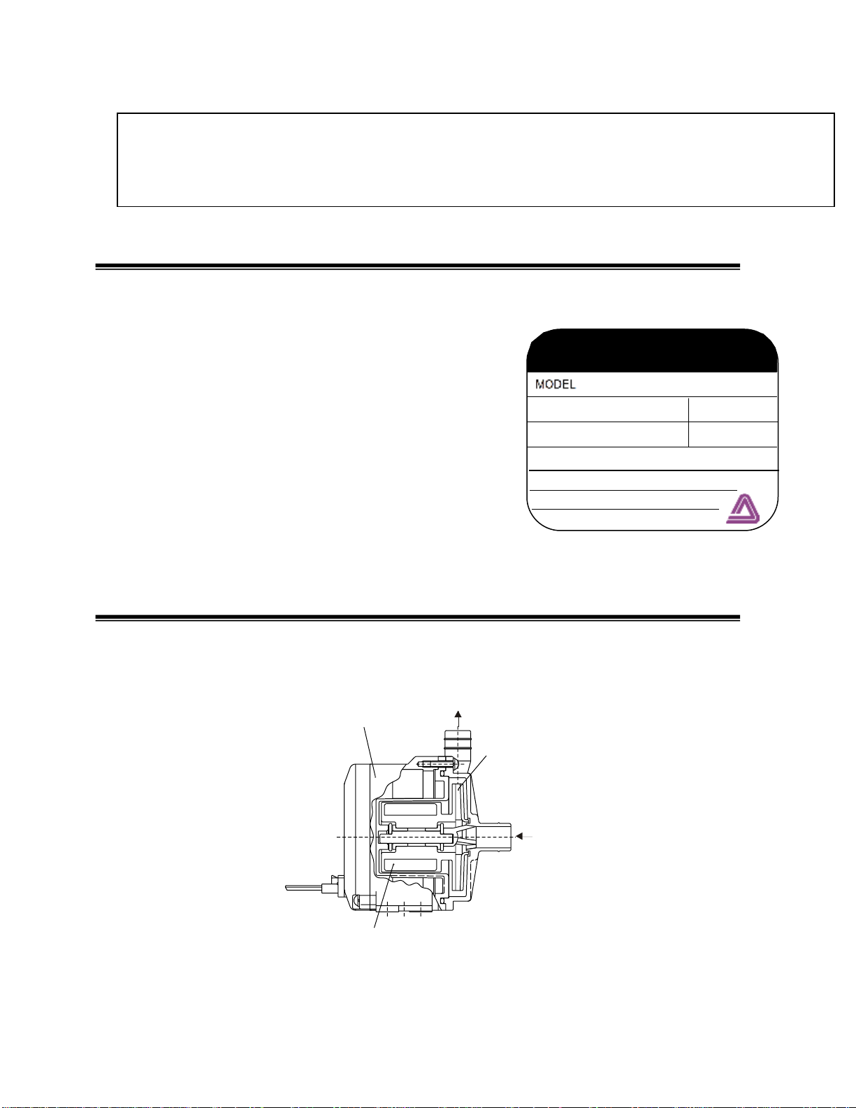
2Operating Principle................................................................................................ 1
3Model Identification Guide.................................................................................... 2
4Specifications ........................................................................................................ 4
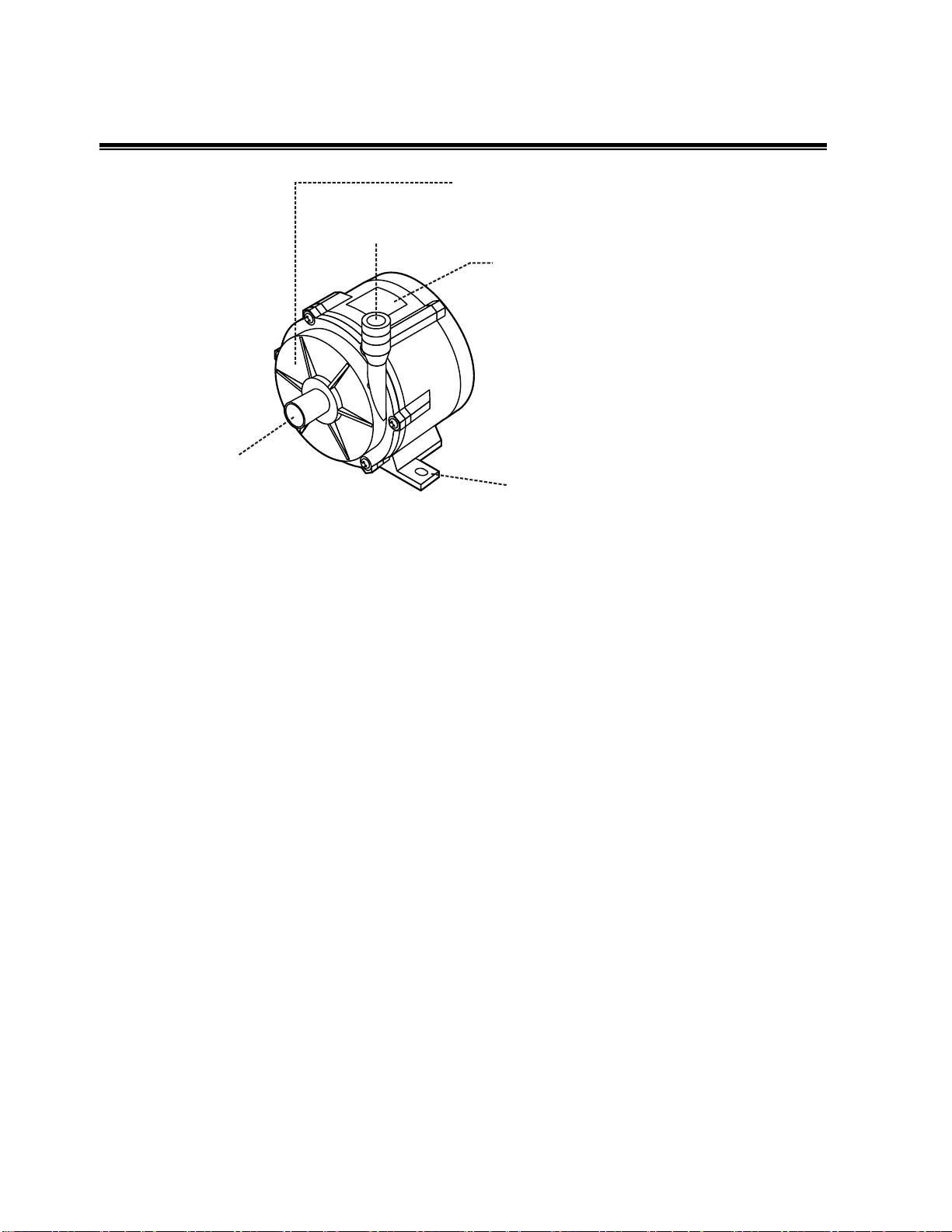
5Main Parts............................................................................................................... 5
6Dimensions ............................................................................................................ 6
7Handling Instructions............................................................................................ 7
8Installation, Piping and Wiring ............................................................................. 8
8.1 Installation ........................................................................................................ 8
8.2 Piping Instructions ............................................................................................ 9
8.3 Wiring ............................................................................................................ 10
9Operation.............................................................................................................. 11
Notes on Operation............................................................................................ 11
Operation ........................................................................................................... 12
Pump Stopping Procedures ............................................................................... 13
How to store pump when it is out of use for a long time..................................... 13
Draining Method................................................................................................. 13
Draining procedure............................................................................................. 14
10 Troubleshooting and Maintenance................................................................. 15
Maintenance....................................................................................................... 15
11 Parts Description ............................................................................................. 16
P/N 180286.G Aug 2012

1
Thank you for selecting the RD Series Direct Drive Pump. This instruction manual explains
the correct handling, operating, maintenance, inspection and troubleshooting procedures for
your pump. Please read through it carefully to ensure the optimum performance, safety and
long service of your pump.
1 Unpacking and Inspection
Open the package and check that the product conforms to your order. Also, check each of the
following points. For any problem or inconsistency, contact your supplier at once.
1. Check that the model number, flow and
head indicated on the nameplate conform to
the specifications of your order.
2. Check that all the accessories you ordered
are included.
3. Check that the pump body and parts have not
been accidentally damaged or that any bolts
or nuts have not been loosened in transit.
2 Operating Principle
The RD Series pump is a canned motor type centrifugal pump driven by a DC brushless
motor. The magnet incorporated with the impeller is directly rotated in the pump chamber by
the magnetic force of the motor to discharge the liquid from suction port to the discharge port.
Iwaki Direct Drive Pump
MAX CAPACITY l/min
MAX HEAD m
VOLTS V
AMPS A
RATING
DO NOT RUN PUMP DRY
MFG No.
IWAKI CO. LTD
TOKYO, JAPAN
Motor
Discharge
Suction
Impeller
Magnet

2
3 Model Identification Guide
RD - 12 T E 24 - N1 V 12
1 2 3 4 5 6 7 8
1Pump size 05, 05H, 12, 12Z, 20, 30
2 Bearing material
No symbol: PPS with filler for RD-05 & 05H
PTFE with filler for RD-20 & 30
T: PTFE
3 O ring material
V: FKM (as an option on RD-12/12Z)
E: EPDM
4 Power source voltage 24: 24VDC
12VDC option available for OEM applications, contact Iwaki America for details.
5 Liquid Temperature Rating
No Symbol: 0 - 40 °C (RD-12, 12Z 0-60°C)
05: 60°C
H: High temperature 0 –80°C
6 Connection (Allowable pressure)
No symbol: Hose
N1: NPT thread (excluding RD-05, 05H, 20, 30)
N2: NPT thread (allowable pressure 0.6 MPa excluding RD-05,
05H, 20, 30)
7 Input signal V: 1 –5VDC
8 Motor Size (excluding RD-05, 05H, 20, 30)
12: 12W (RD-12) 14: 14W (RD-12Z)
RD-12/12Z/30 only

3
RD - 40 E 24 - H V
1 2 3 4 5 6
1 Pump size 40, 40X
2 O ring material V: FKM E: EPDM
3 Power source voltage 24: 24VDC
4 Liquid Temperature range H: High Liquid Temperature
0 –80°C
5 Connection No symbol: Hose
R1: R Thread
N1: NPT thread
6 Input signal V:1 –5VDC
.

4
4 Specifications
Model
Connections (Hose)
Max flow
GPM
(L/min)
Max head
FT (m)
Max
Specific
Gravity
Motor
Weight
Lbs (kg)
Suction
Inches (mm)
Discharge
Inches (mm)
Power (V)
Rated output
(W)
RD-05
0.55 (14)
0.32 (8)
1.2 (4.7)
11.8 (3.6)
1.0
DC24
4.4
0.9 (0.4)
RD-05H
0.55 (14)
0.32 (8)
2.1 (7.9)
36.1 (11)
1.0
DC24
18
1.1 (0.5)
RD-12
3/8 NPT
0.71 (18)
3.4 (12.7)
22.3 (6.8)
1.0
DC24
12
1.3 (0.4)
RD-12Z
3/8 NPT
0.71 (18)
1/4 NPT
0.4 (10)
1.0 (3.8)
34.4 (10.5)
1.0
DC24
14
1.3 (0.4)
RD-20
0.71
(18)
5.2 (19.5)
30.5 (9.3)
1.0
DC24
28
2.9 (1.3)
RD-30
0.71
(18)
6.2 (23.5)
37.7 (11.5)
1.0
DC24
45
2.9 (1.3)
RD-40
1 NPT
1 (25)
1/2 NPT
0.75 (19)
6.6 (25)
49.2 (15)
1.0
DC24
85
3.3 (1.5)
RD-40X
1 NPT
1 (25)
3/4 NPT
1 (25)
18.5 (70)
26.2 (8)
1.0
DC24
72
3.3 (1.5)
Notes:
1. Performance data is based on pumping clear water at ambient temperature.
2. Max. flow based on discharge pressure of 0 psi and max. head based on operating pump at shut-off.
3. Max. allowable viscosity of liquid (at specific gravity 1.0): 1 cP (1mPa-s).
4. Ambient installed temperature range: 32 –104 °F (0 - 40 °C).
5. Max. specific gravity is the value at maximum flow.
6. Motor specifications:
Pumps use a DC brushless motor equipped with the following protective functions in drive circuitry:
a. Protection against jammed impeller.
Drive circuitry will detect locked impeller and stop the pump.
b. Excessive temperatures.
The pump will stop when the motor temperature increases beyond rated temperature as a result of elevated
fluid temperature or installed environment temperature.
c. Over current protection.
The drive circuitry is protected against excessive current ( Note, RD-05 has no over current protection because
of its low output).
d. Fuse
RD’s are equipped with internal fuse to protect pump form overheating or causing damage to system when
drive circuit has been damaged. The built-in fuse cannot be replaced, so, we recommend use of an external
fuse.
Performance and dimensions of pumps may be changed without prior notice.

5
5 Main Parts
Pump unit
(Liquid feeding unit)
Discharge port
Suction port
Specifications label
Use the pump according to
the specifications on the
label.
Base
Fix the pump securely.

6
6 Dimensions
Dimensions in inches (mm)
Model
W
H
L
a
b
c
d
e
f
g
k
RD-05
2.99
(76)
2.95
(75)
3.72
(94.5)
0.63
(16)
1.18
(30)
2.52
(64)
1.18
(30)
1.16
(29.5)
0.88
(22.4)
1.98
(50.5)
2-5x7
RD-05H
2.28
(58)
3.07
(78)
4.25
(109.5)
3.54
(90)
3.94
(100)
1.38
(35)
1.30
(33)
1.16
(29.5)
0.88
(22.4)
0.57
(14.5)
2-2x6
RD-12
3.07
(78)
3.21
(81.5)
3.68
(93.5)
0.63
(16)
1.18
(30)
2.60
(66)
1.20
(30.5)
1.24
(31.5)
0.71
(18)
2.05
(52)
2-5x7
RD-12Z
3.07
(78)
3.13
(79.5)
3.68
(93.5)
0.63
(16)
1.18
(30)
2.60
(66)
1.20
(30.5)
1.24
(31.5)
0.78
(19.8)
2.05
(52)
2-5x7
RD-20/30
4.41
(112)
4.69
(119)
4.33
(110)
0.87
(22)
1.46
(37)
3.82
(97)
1.93
(49)
1.38
(35)
1.42
(36)
2.34
(59.5)
2-6x8
RD-40
4.96
(126)
5.47
(139)
5.0
(127)
0.87
(22)
2.12
(54)
4.25
(108)
2.28
(58)
1.65
(42)
1.46
(37)
2.95
(75)
4-ø6x10
RD-40X
4.96
(126)
5.63
(143)
5.0
(127)
0.87
(22)
2.12
(54)
4.25
(108)
2.28
(58)
1.65
(42)
1.57
(40)
2.95
(75)
4-ø6x10
LW
a
b
g
k
d
H
f
e(58)
c
(12)
ag
bLW
d
H
f
(106)
e
k
c
(15)
aLg
d
c
H
b(50)
ef
W
e
W
L
d
H
f
(121)
b
ag
k
RD-40(X)
k
RD-20/30
RD-05/12(Z) RD-05H

7
7 Handling Instructions
Warning
Switch off the power when the pump or its electrical parts get wet.
Keep the pump away from fire
Do not place dangerous or flammable substances near the pump.
Caution
Keep the impeller assembly away from any electronic device that could be
affected by a strong magnetic field.
Do not run pump dry, this will result in excessive bearing wear and frictional
heat damaging the pump.
1. Handle the pump carefully
Impacts caused by dropping the pump
on the floor or striking it may result in damage
or faulty performance.
2. Priming water
Be sure is installed with flooded suction and is full of
liquid before operating.
3. Magnet
There is a powerful magnet inside the
pump liquid end, do not use any liquid that
contains metallic substances such as iron,
nickel, etc.
4. Do not install/operate the pump in the following places
Places where the ambient temperature falls below 32°F (0°C).
Places where corrosive gas (such as chlorine gas) is generated.
Places exposed to splashing or dripping water.
Places where the ambient temperature is 104 °F (40°C) or above.
Places where explosive vapors or gases may be present.
The pump unit is not designed to be dust and waterproof.

8
5. Do not operate the pump with the following liquids
Liquids that significantly are not compatible with materials of construction.
Examples; Paraffinic hydrocarbons such as gasoline and kerosene.
Halogenated hydrocarbons such as trichloroethylene and carbon
tetrachloride.
Slurry
(Never use pumps in slurry applications, as premature bearing wear will result in
pump failure.)
For compatibility with chemical liquid or any special liquid, contact Iwaki America customer
service.
6. If pump is damaged
Do not operate a damaged pump, electrical shock or a short circuit may occur.
7. Power cable
A broken or frayed power cable may cause an electrical shock. Do not bend, pull or twist
power cords. Consult Iwaki America customer service if power cable is damaged and needs to
be replaced.
8. Cleaning the pump
Do not clean the exterior of the pump with a solvent such as Benzene, alcohol, etc.
8 Installation, Piping and Wiring
8.1 Installation
Pump Location
The pump must be installed in a location with an ambient temperature of 32 –104°F (0-40°C)
and a relative humidity lower than 85%. It is recommended the pump be installed so that it is
easy to inspect and maintain..
Pump Position
This pump is not the self-priming pump. The pump
must be installed in a position lower than the liquid
level of the supply tank. Recommended liquid level above
pump suction is 12 inches (30 cm). This is to prevent the pump
form sucking in air which will result premature or
accelerated bearing wear.

9
Pump base mounting
The base of the pump must be anchored firmly to the mounting surface.
It is recommended that the unit be installed in a horizontal position,
however vertical mounting is acceptable provided adequate liquid level
above inlet is present and air is properly vented.
8.2 Piping Instructions
The shortest pipe possible, with the minimum number of bends, should be designed.
Arrange a proper support on the suction pipe so that the load and the thermal stress of the
pipe itself are not applied to the pump.
.
Use a corrosion-resistant vinyl hose that can endure the pressure created during
pump operation. If the connection on the suction side is inadequate, air may be mixed in.
Hose size
Select a hose in accordance with the diameter of the pump port. A reliable connection is
not guaranteed if a different size hose is used.
As the hose on the suction side, in particular, tends to be crushed under the sucking force,
the use of a braided hose is recommended. (In case of hot liquid feeding, special
attention must be paid in the selection of the hose.)
Valve installation
Install valves close to the suction and discharge port.
Suction side:
For easy removal or maintenance of the pump.
Discharge side valve:
For adjustment of the discharge rate or head.
Hose connection
Press the hose end firmly against the discharge
or suction port until it reaches the bottom of
the port.
* Use a fastener (such as a hose band) to make the connection firm and free of liquid
leakage.

10
Caution
Do not tighten the connection ports (suction and discharge) excessively as they
are made of plastic resin and are easily damaged.
Pay attention the load is not applied to inlet and outlet port.
8.3 Wiring
Before you start wiring works, make sure the main power is switched off.
Use appropriate wiring materials, follow the instruction manual for the motor and abide
by the local and national electrical codes.
Use specified voltage written on pump nameplate.
Pump has no ON/OFF switch. Pumps start when power cable is connected. Do not
frequent ON/OFF operation.
In case external fuse is installed
When the fuse blows out, replace it and start pump after you settled the reason of blew
out fuse. If the fuse blows out frequently, it may be caused by the starting current.
Wires have polarity. Red is plus and black is minus. Wrong polarity will damage
the motor. Motor does not rotate in reverse if the wires are connected in reverse.
Rated current, starting current
Model
Rated Current
Starting Current
RD-05V24
0.4A
1.5A
RD-05HV24
1.6A
4.0A
RD-12
1.0A
3.2A
RD-12Z
1.0A
5.0A
RD-20V24
2.5A
8.0A
RD-30V24
3.2A
10.0A
RD-40
5.5A
10.0A
RD-40X
5.3A
10.0A
Rib Hose
Clamp

11
If pump is switched ON and OFF, install the switch at the secondary side of DC
power source (between power sources and pump). If power is ON and OFF at the
primary side of DC power source, it is possible pump can not start.
Three (3 )Wire Pumps
Red = 24 VDC
Black = GND * Note:Commonforboththemain powersupplyandspeedcontrol input
White = 0-5 VDC speed control
If two (2) power sources are not available, the white wire can be connected directly to 24
VDC to achieve full speed operation.
* Note: Must be less than 26.4 VDC or damage can occur
9 Operation
Notes on Operation
Caution
1. Before operating the pump, confirm that the pump is securely fixed and the hoses
connected with the discharge port and suction port are firmly fixed in position.
2, Dry operation (operation without liquid in the pump) damages the pump. Be sure to fill
the pump with priming liquid in advance.
3. Do not keep on operating the pump with entirely or almost closed discharge or/and
suction side valve(s).
4. Do not open or close the suction or discharge side valve suddenly, otherwise the
protective circuit operates, disabling the rotation of the impeller. (Under such
circumstances, turn off the power supply.)
5. Frequent ON and OFF may cause the failure or damage of pump.
6. If foreign matters get into the pump, switch off power and remove them. Otherwise pump
may be failed or damaged.
AC power Pump
DC power
source
Good
AC power Pump
No good
DC power
source

12
Operation
After the installation, piping and wiring processes are completed, operate the pump in
accordance with the following steps.
No.
Operation Step
Description (Points to be checked)
1
Check piping, wiring and
voltage
Check in accordance with the ‘Hose connection’
and ‘Wiring’ sections. Check the power supply
voltage by referring to the information on the
nameplate.
2
Open and close valves
Fully open suction side valve.
Fully close discharge side valve.
3
Check that pump chamber
is filled with liquid
Fill pump chamber with priming water (feeding
liquid).
Carry out sufficient priming in case of suction lift
method.
4
Supply power to pump
After step 1 to 3 above, connect power supply to
start pump.
When pump is switched ON and OFF, take the
interval of five or more seconds to switch ON
again after switched OFF.
5
Adjust discharge capacity &
head to desired ones
Adjust discharge side valves gradually till desired
discharge capacity and head are obtained. Do not
open or close valves suddenly.
Note: Do not keep discharge side valve closed for
more than 1 minute for flow rate of 0.1L/min. or
less
Note: Check that pump feeds liquid normally. If
not, turn off power immediately and eliminate
cause referring to ‘Causes of Trouble and
Troubleshooting’ section.
6
Checkpoints during
operation
Be careful to prevent foreign matters from
entering the pump. Foreign matters in pump may
cause impeller to be locked, hindering liquid
circulation. Motor itself continues to rotate even if
impeller is locked. In such a case, turn off power
supply at once.

13
Pump Stopping Procedures
No.
Stopping Step
Description
1
Close discharge side valve
Close discharge side valve gradually.
Do not use electromagnetic valve for
quick closing.
2
Turn off power supply. (Check
stopping condition.)
Check that motor stops smoothly
after power is disconnected. If not,
pump should be inspected. (For
details, contact Iwaki or your dealer.)
How to store pump when it is out of use for a long time
Remove the liquid from the pump when it is stored for a long time. In addition, run it with
water circulating for about 5 minutes every 3 months to prevent rust on the motor bearing.
Draining Method
Warning
1. Before starting the draining procedure, turn off the power supply.
2. Be sure to wear proper safety gear (gloves, protective shoes, etc.) during draining work.
When chemical liquid is used, wear rubber gloves, goggles).
Caution
3. Pay special attention to the remaining liquid which may run out of the discharge port or
the suction port when removing the hose. Pay attention not to allow the motor or electric
parts to come into contact with the liquid.
4. Never discharge hazardous or chemical liquid over the ground or floor in the plant.
Instead, use a draining pan (or container). Observe each applicable local law or regulation
for the handling or disposal of hazardous liquids.
5. Motor is not dust and waterproof construction. Do not wet pump.

14
Draining procedure
1. Turn off the power supply. (Make sure no other operator will turn on the power supply
accidentally.)
2. Fully close the discharge and suction sides valves.
3. Remove the hoses connected with the discharge and suction ports.
Position the draining pan below the pump unit in advance. Loosen the hose band and rotate
the hose clockwise and counterclockwise slowly to completely pull the hose off of each port.
(Liquid will run out when the hose is disconnected.)
4. Remove the screws on the pump base to detach the pump unit.
5. Direct the discharge port downward to drain the liquid into the draining pan.
Never discharge hazardous liquid, over the ground or the floor inside the plant. Use a
draining pan (or container).

15
10 Troubleshooting and Maintenance
Cause
Excessive
heat
Pump does
not start
Insufficient
pumping
Electric
current
is too
high
Excessive
noise or
vibration
Liquid
leaks
Troubleshooting
Power is not supplied or wiring is faulty
Check and correct
wiring
Motor is out of order (disconnect coil or
capacitor failure)
Contact your dealer
Air in pump
Eliminate air
completely
Air is sucked in via suction port
Fasten hose tightly
Pump runs dry
Check piping
Specific gravity/viscosity of liquid is too
high
Use suitable type of
pump
Impeller magnet touches rear casing
Contact your dealer
Impeller is damaged
Contact your dealer
Foreign matter adheres to impeller
Contact your dealer
O ring is damaged
Contact your dealer
Loosened front casing fixing bolts
Tighten bolts
Too high liquid & ambient temperature
Contact your dealer
Lack of power volume
Check power volume
Maintenance
1. Tighten bolts
While the pump is running for a long time, it may happen the bolts are loosened. In this case
tighten the bolts. Also tighten the bolts after the pump are stocked for a long period.
2. Daily Inspection
Check to see the operating condition of the pump such as vibration, sound, electric current
and flow rate and as soon as you find any abnormality, switch off the power and settle the
abnormality referring to the item “Troubleshooting”.
3. Spare Parts (Consumable parts)
When the pump is continuously used for a long period, we recommend you to stock
consumable parts such as impeller and O ring.

16
11 Parts Description & Materials
05, 05H
12, 12Z
20, 30
40, 40X
1 Casing
GFRPPE
GFRPPS
PPE
GFRPPS
2 Rear casing
GFRPPE
GFRPPS
PPE
GFRPPS
3 Impeller
GFRPP
GFRPPS
GFRPP
GFRPPS
4 Spindle
Alumina Ceramic
5 Bearing
PTFE/PPS
PTFE
PTFE
PTFE
6 Thrust ring
Alumina Ceramic
7 O-ring
FKM or EPDM
This manual suits for next models
8
Table of contents
Other IWAKI AMERICA Water Pump manuals

IWAKI AMERICA
IWAKI AMERICA WMD-100 Series User manual

IWAKI AMERICA
IWAKI AMERICA MW-250 Series User manual

IWAKI AMERICA
IWAKI AMERICA Sanwa MMP User manual

IWAKI AMERICA
IWAKI AMERICA MDF-L Series User manual

IWAKI AMERICA
IWAKI AMERICA MXM Series User manual

IWAKI AMERICA
IWAKI AMERICA MDE Series User manual

IWAKI AMERICA
IWAKI AMERICA EH Series User manual

IWAKI AMERICA
IWAKI AMERICA MD SERIES User manual

IWAKI AMERICA
IWAKI AMERICA Walchem EWN-R User manual

IWAKI AMERICA
IWAKI AMERICA Walchem EWN-Y User manual