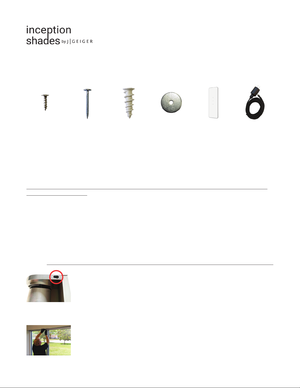
J GEIGER inception shades User manual

INCEPTIONSHADES.COM
Installation Guide
STEP 1
Remove shade from box. Locate the following components:
3/4” modified truss head screws (3x) - Use with washers when mounting shade to wooden surfaces such as window trim.
1-5/8” modified truss head screws (3x) - Use with washers when mounting to shade to sheetrock.
Sheetrock anchors (3x) - Use with 1-5/8” screws and washers when a stud is not present.
Washers (3x) - Use with modified truss head screws.
Charger - Included with wire-free rechargeable shades only.
Cable for wire connections - Included with wired RF and smart shades only.
Pre-programmed 1ch remote - Included with wire-free rechargeable and RF shades. Not included with smart shades.
Remotes ship with flipped batteries to prevent shade movement. Open remote and flip batteries before use.
Use provided hardware. Never substitute modified truss head screws with sheetrock screws. Call 844-543-4437 to
report missing components.
STEP 2
Ensure that shade measurements are as ordered and that shade will fit window as expected.
STEP 3
Apply a piece of painter’s tape to the wall or trim centered above the window opening where the shade is to be mounted.
Draw a line to mark center.
STEP 4
Remove back mounting plate from shade band by applying force to the spring loaded safety lock lever (located on shade
brackets). Practice clipping and unclipping band from plate. A solid connection will be imperative when hanging shade.
STEP 5
Hold mounting plate over the marked line. Use the plate as a guide to mark center screw location on wall or window trim.

INCEPTIONSHADES.COM
STEP 6
For sheetrock application, test to see if there is a stud behind the marked center screw location. Use a stud finder, a 1/16
drill bit, or the mounting screw provided. If stud is present, drill pilot hole for 1 5/8” modified truss head screw. If no stud is
present, screw a sheetrock anchor into the marked location until it is flush with the wall surface (3/16 drill bit recommended
for sheetrock anchor pilot hole).
For wooden trim, drill pilot hole for 3/4” modified truss head screw. Anchors are not necessary when mounting to wood.
STEP 7 (wired shades only)
For wired shade, drill a hole in the mounting plate to pull magnetic cable through. Hole placement is flexible, since wires
will be concealed by the shade band, but magnetic end of cable will need to reach drive side bracket.
STEP 8 (wired shades only)
For wired shade, cut magnetic cable. Discard USB end. Remove several inches of rubber jacket. Strip wires, leaving 3/8” of
exposed copper. Use dolphin connectors to splice wires from wall with cable.
STEP 9
Place washers on mounting screws.
For wired shade, pull magnetic cable through drilled hole in mounting plate before attaching plate to wall. Tape can be used
to secure cable to mounting plate.
Align mounting plate so that it is centered over and parallel with the window. Center screw within the oblong punch-out.
Use a screwdriver to screw in center screw. Never use an impact driver. Force from an impact driver will damage the
mounting plate.
STEP 10
Check to ensure that mounting plate is level. Tighten center screw and use mounting plate as a guide to mark left and right
screw locations.
Installation Guide
STEP 9
Check to ensure that mounting plate is level. When level, mark the left and right screw locations.
For JG Smart Motor:For RF Motor:

INCEPTIONSHADES.COM
STEP 11
For sheetrock application, test to see if studs are present behind marked screw locations (left and right).
a. If studs are present, mount plate with provided screws and washers (left and right side).
b. If studs are not present, remove the plate from the wall, screw in anchors until they are flush with the mounting surface,
and re-mount plate with provided screws and washers (left and right side).
For wooden trim, mount plate with provided screws and washers through the punch-outs (left and right side).
Use a screwdriver. Never use an impact driver. Force from impact driver will damage mounting plate.
STEP 12
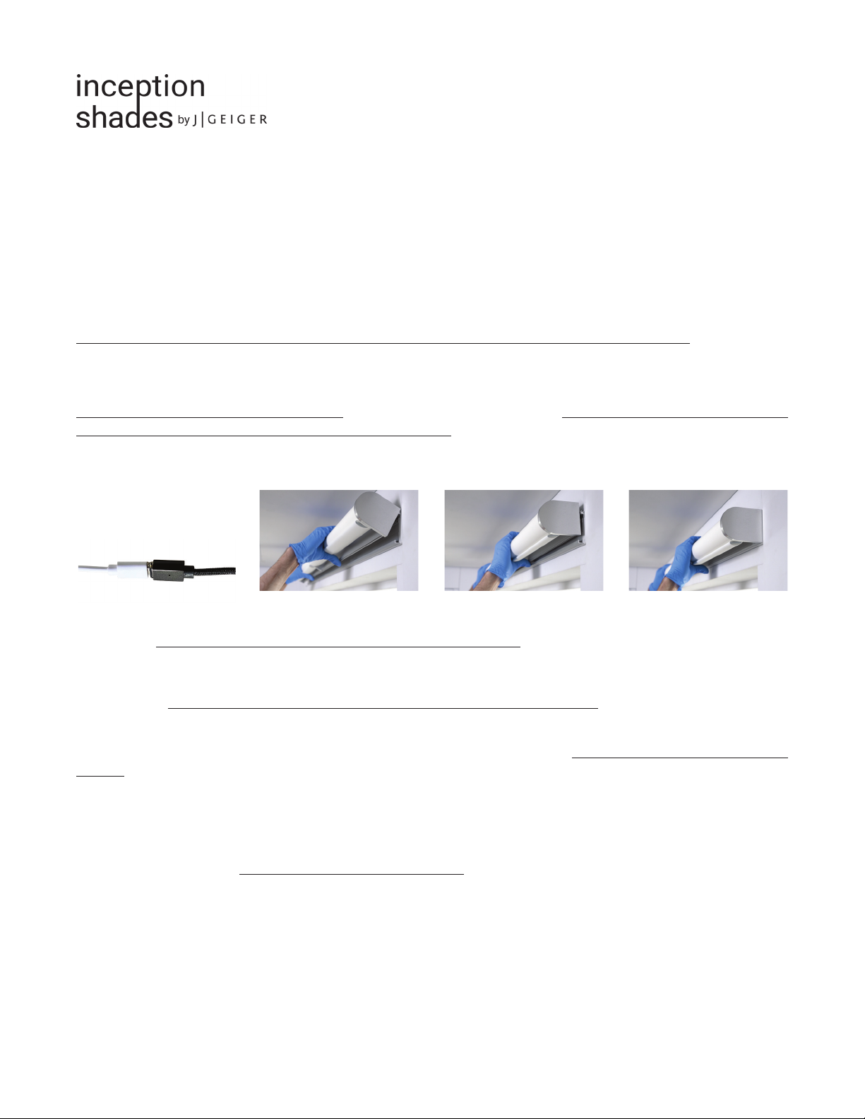
Engage shade locks (located on brackets) with finger or angled pick tool and slide shade band down over the back plate.
Shades over 6 feet will require two people. Release lever to lock shade in place. Double check to make sure locks are
secure (angled pick recommended). Unlocked shades will fall. Check along the entire length of the band to ensure shade
is secure. The front band should not move while shade is operating. If band moves while shade is in motion, remove the
shade band and attempt locking process again.
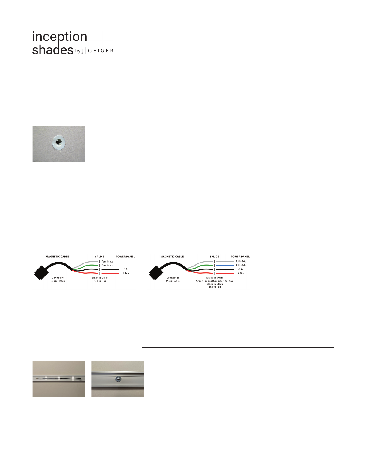
For wired shades, connect
magnetic cable to motor
cable.
STEP 13*
Please Note: Wire-free shade motors will need to be charged before use. Shipping restrictions prevent the transport of
fully charged motors.
Using the provided pre-programmed remote, check shade limits. Remote batteries will be flipped to prevent shade movement
while shipping. Open the remote back and flip batteries before checking shade limits.
Shade’s top limit will be set. The bottom limit will require adjustment.
a. Setting the Bottom Limit — Bring the shade to its current bottom limit. Then press and hold the down and stop
buttons at the same time. The shade should jog up and down, indicating that it is in programming mode. Press the up or
down button to move the shade to desired lower limit (the point at which shade will stop when going down). When the shade
is at the new desired limit, press down and stop at the same time to set the command. The shade should jog up and down
again when exiting programming mode and to confirm the limit is set.
b. Setting the Top Limit — The top limit is pre-programmed but can be adjusted as needed. To adjust top limit, bring the
shade all the way up. Then press and hold up and stop buttons at the same time. The shade should jog up and down,
indicating that it is in programming mode. Press the up or down button to move the shade to desired upper limit (the point at
which shade will stop when fully up/open). When the shade is at the new desired limit, press up and stop at the same time to
set the command. The shade should jog up and down again when exiting programming mode and to confirm the limit is set.
*Limit programing instructions applicable to Rollease wire-free and RF motors. Not applicable to J Geiger motors.
GREAT WORK
Please call 844-543-4437 to report missing components or if you experience technical difficulty.
Installation Guide
Table of contents
Other J GEIGER Indoor Furnishing manuals
Popular Indoor Furnishing manuals by other brands

Wren
Wren TOWER UNIT 2070 Assembly guide

Julian Bowen Limited
Julian Bowen Limited Maine MAI111 Assembly instructions

FRISKA
FRISKA Primo Assembly instructions

Classic Exhibits
Classic Exhibits MAGELLAN DESIGNS VK-1088 quick start guide

Kogan
Kogan Shangri-La SEATTLE SLSTDAYBWA user guide

Discovery Telecom
Discovery Telecom 2108 instruction manual

Philips
Philips 288720 operating instructions

Idea Group
Idea Group AQUA 01AQ Assembly instructions

Studio Trends
Studio Trends STLD46 Assembly instructions

HOMCOM
HOMCOM 313-001V01 manual

Nags Head Hammocks
Nags Head Hammocks Classic Adirondack Rocker instructions

Walker Edison
Walker Edison JLLF6F Assembly instructions