3
ASSEMBLY INSTRUCTIONS
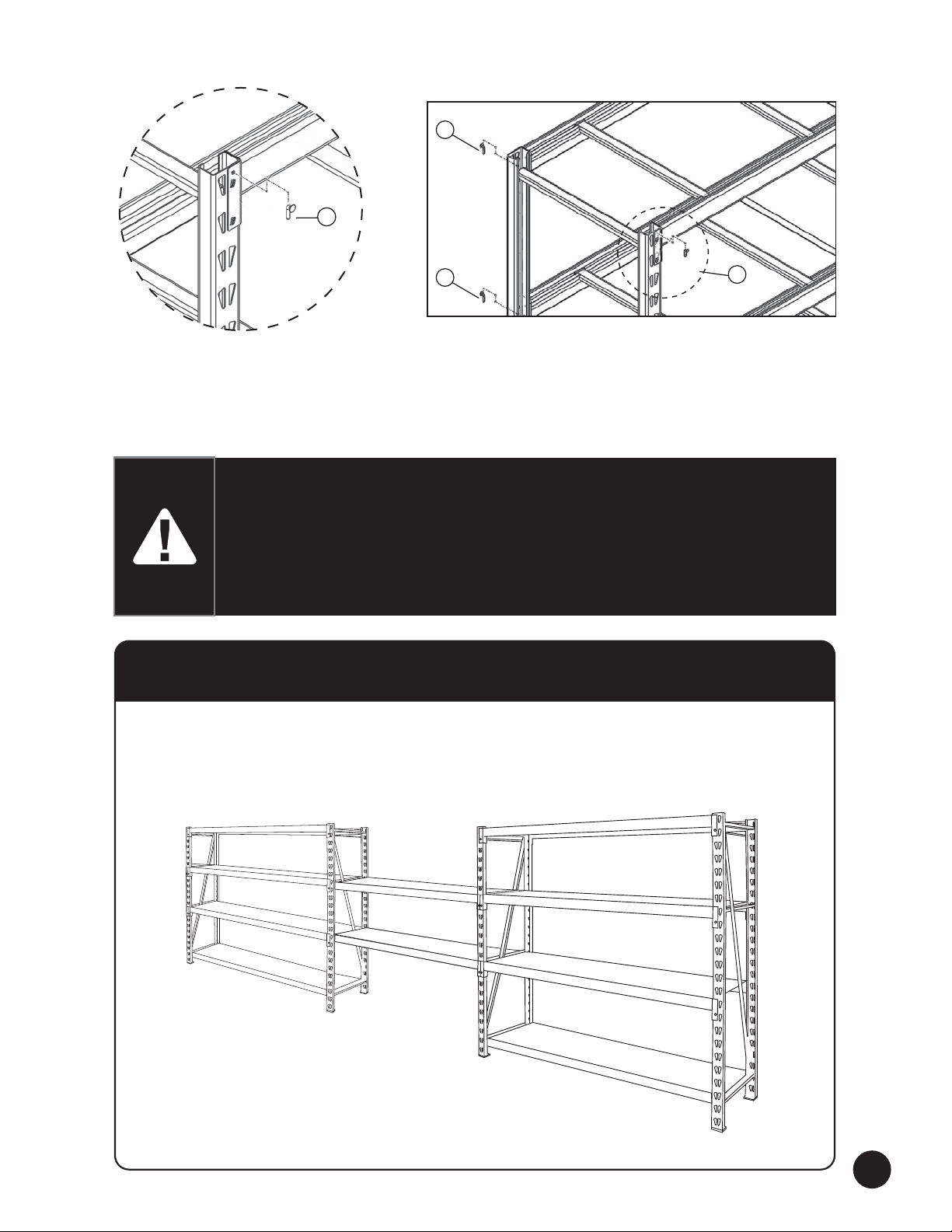
Fig. 1 Fig. 1a
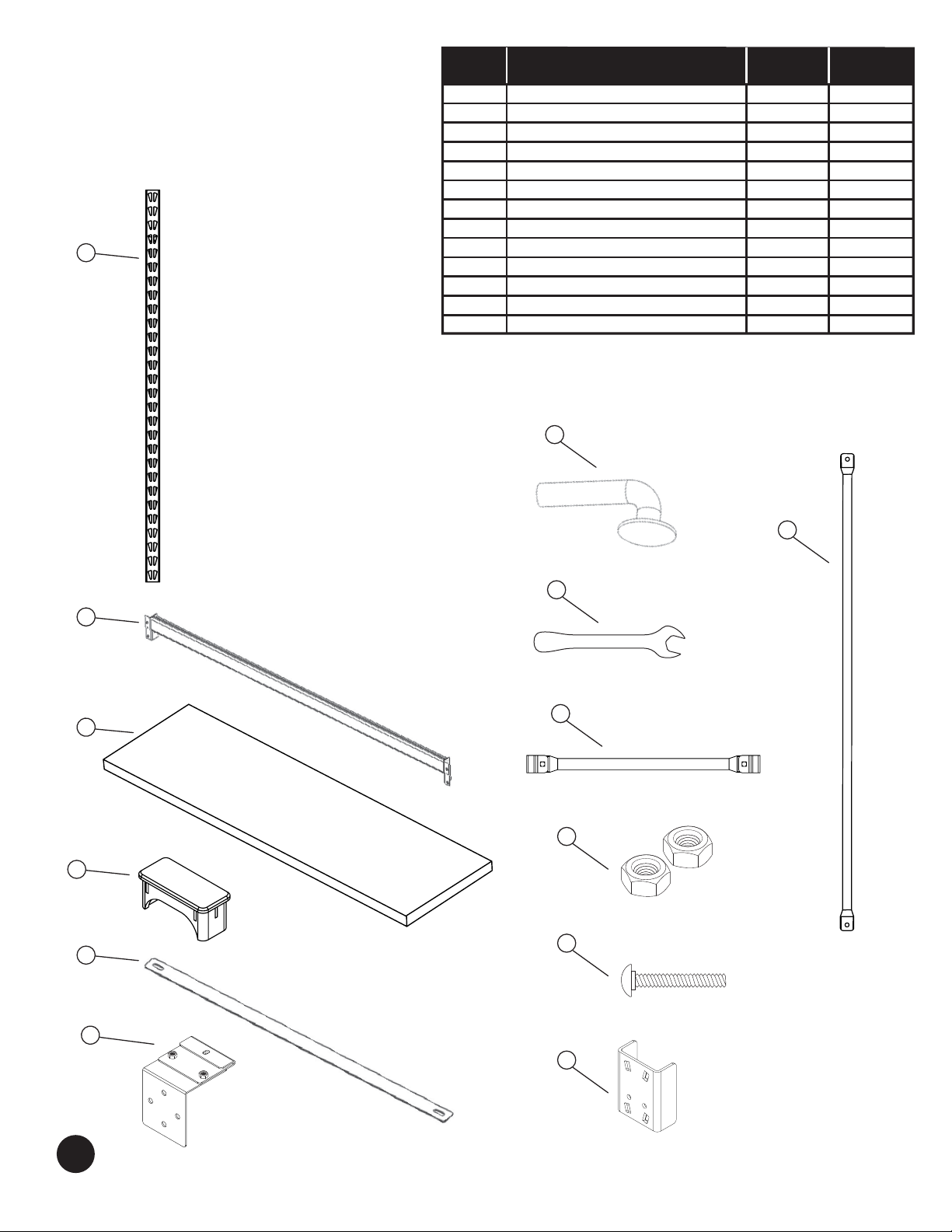
1. Remove 2 of the uprights from the box.
2. Cut away any protective material that may be applied.
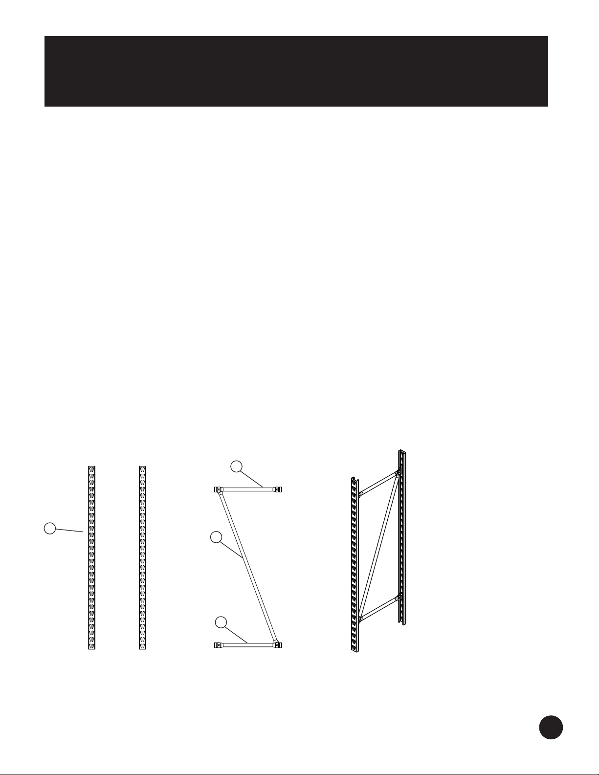
3. Pull the 2 uprights(A) apart, placing them parallel to one another about 2ft. (61 cm) apart 2 uprights (A). Pay
close attention that the hole pattern on both upright beams are all facing the same direction.
4. At the top of the upright (A) insert the short horizontal beam into the “U” shaped bracket and align the holes.
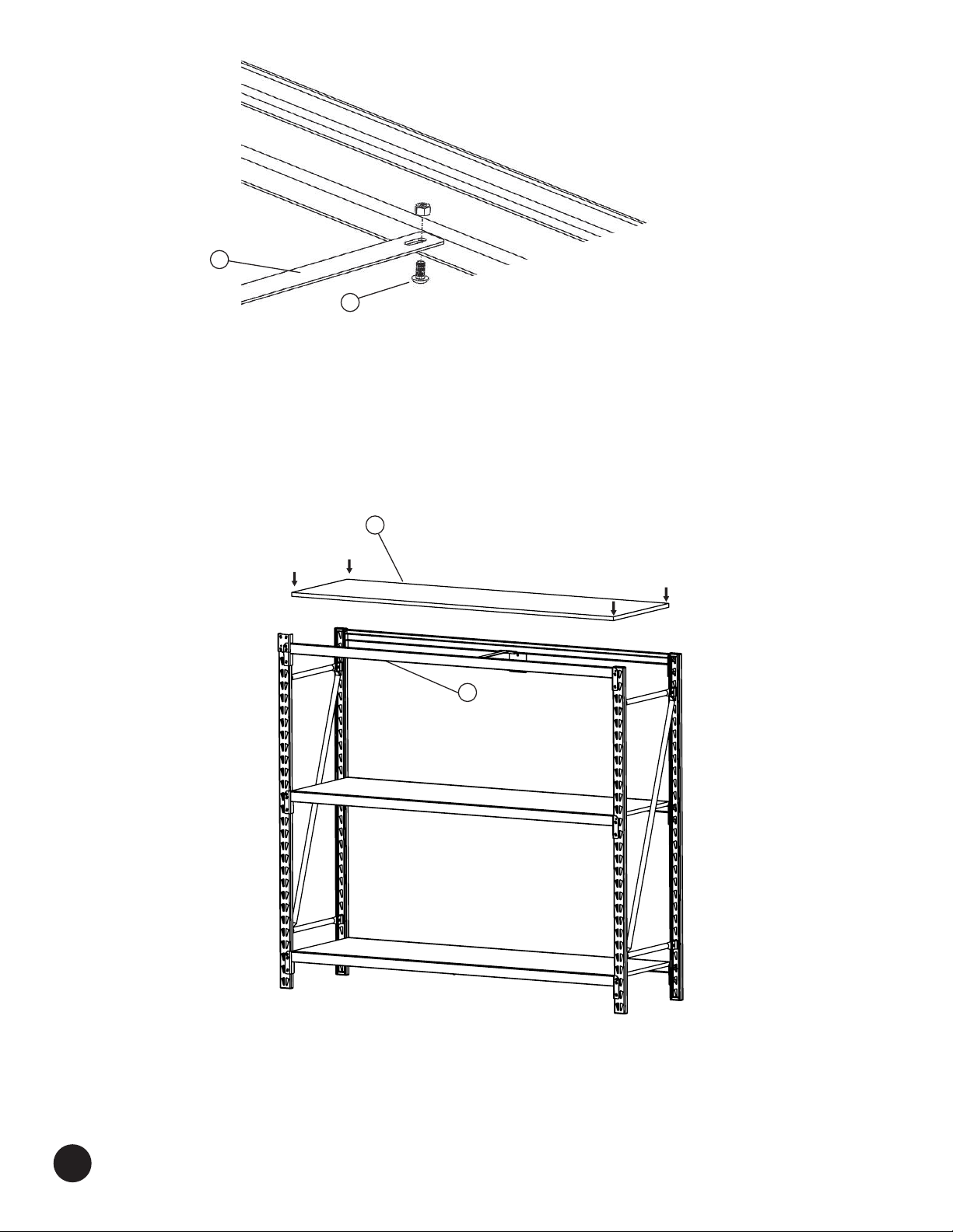
After doing so place screw (L) into the hole and apply nut to the opposing side, (do not tighten until the
assembly is complete).
5. At the top of the upright (A) insert the opposing end of the short horizontal beam that was placed into the (J)
upright and the long diagonal beam (I) into the “U” shaped bracket and align the holes. After doing so place
screw (L) into the hole and apply nut to the opposing side, (do not tighten until the assembly is complete).
6. Repeat the steps 4 and 5 for the bottom portion of the upright assembly as shown in Figure 1a.
7. After parts (A), (J), and (I) are fully attached and secured into place, tilt against a wall at a slight angle.
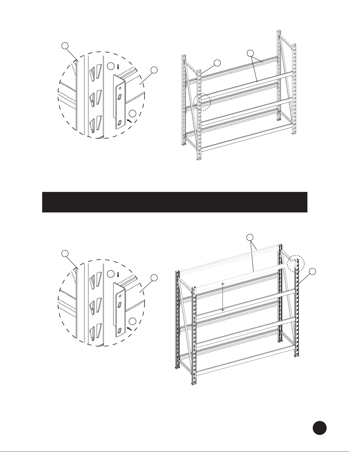
8. Take the supplied hex key tool and tighten the bolts on all 4 corners ensuring that the diagonal and horizontal
beam and uprights are at 90 degrees/square.
9. Be sure not to over-tighten the bolts. There should be no deformation of the U-shaped bracket and/or
horizontal beams.
10. When assembly is complete place and tap into place the caps and feet (D) using a rubber mallet.
I
J
J
A
NOTE - Check all of the components provided for defects. If any defects are found, do not
proceed with assembly. Use of defective components or improper assembly may result in
damage or injury. Before placing a load on the shelves, make sure all of the tabs are locked
into place securely.