J-KEM Scientific Gemini-230 User manual

Temperature Control For Research and Industry
Model
Gemini-230
Manual
For Serial Number

2

3
Warranty
J-KEM Scientific, Inc. warrants this unit to be free of defects in materials and workmanship and to give
satisfactory service for a period of 12 months from date of purchase. If the unit should malfunction, it
must be returned to the factory for evaluation. If the unit is found to be defective upon examination by J-
KEM, it will be repaired or replaced at no charge. However, this WARRANTY is VOID if the unit shows
evidence of having been tampered with or shows evidence of being damaged as a result of excessive
current, heat, moisture, vibration, corrosive materials, or misuse. This WARRANTY is VOID if devices
other than those specified in Section 3.2 are powered by the controller. Components which wear or are
damaged by misuse are not warranted. This includes contact points, fuses and solid state relays.
THERE ARE NO WARRANTIES EXCEPT AS STATED HEREIN. THERE ARE NO OTHER
WARRANTIES, EXPRESSED OR IMPLIED, INCLUDING BUT NOT LIMITED TO THE IMPLIED
WARRANTIES OF MERCHANTABILITY AND OF FITNESS FOR A PARTICULAR PURPOSE. IN
NO EVENT SHALL J-KEM SCIENTIFIC, INC. BE LIABLE FOR CONSEQUENTIAL, INCIDENTAL
OR SPECIAL DAMAGES. THE BUYER'S SOLE REMEDY FOR ANY BREACH OF THIS
AGREEMENT BY J-KEM SCIENTIFIC, INC. OR ANY BREACH OF ANY WARRANTY BY J-KEM
SCIENTIFIC, INC. SHALL NOT EXCEED THE PURCHASE PRICE PAID BY THE PURCHASER
TO J-KEM SCIENTIFIC, INC. FOR THE UNIT OR UNITS OF EQUIPMENT DIRECTLY
AFFECTED BY SUCH BREACH.
Service
J-KEM Scientific maintains its own service facility and technical staff to service all parts of the controller,
usually in 24 hours. For service, contact:
J-KEM Scientific, Inc.
858 Hodiamont Ave.
St. Louis, MO 63112
USA
(314) 863-5536
fax (314) 863-6070
E-Mail: jkem911@jkem.com
Internet on-line catalog: www:jkem.com
This manual contains parameters specific to this temperature controller.
When calling with a technical question, please have the controller’s serial number available.
You’ve purchased the most versatile controller available to the research community. We’re
confident it can regulate ANY heating/cooling situation you’ll ever encounter. If the information in this
manual isn’t adequate for your application, contact our Engineering Department for assistance.
–With J-KEM’s patented Microtune circuitry –

4
INDEX
SECTION PAGE
1. QUICK OPERATING INSTRUCTIONS . . . . . . . . . . . . . . . . . . . . . . 4
SAFETY NOTICES .... . . . . . . . . . . . . . . . . . . . . . . . . . . . . . . . . . . . . . 5
KEM-NET DATA LOGGING AND CONTROL SOFTWARE . . . . . 6
2. ADJUSTING THE CONTROLLER FOR STABLE
CONTROL WITH DIFFERENT HEATERS. . . . . . . . . . . . . . . . . . . . 7
2.1 What is Tuning. . . . . . . . . . . . . . . . . . . . . . . . . . . . . . . . . ........7
2.2 Autotuning Procedure. . . . . . . . . . . . . . . . . . . . . . . . . . . . . . . . . . . 8
2.3 Tuning for Heating Mantles: A Special Case .... . . . . . . . . . . . . 10
2.4 Sensor Placement . . . . . . . . . . . . . . . . . . . . . . . . . . . . . . . . . . . . . . 10
3. OPERATIONS GUIDE . . . . . . . . . . . . . . . . . . . . . . . . . . . . . . . . . . . . . 11
3.1 Front Panel Description. . . . . . . . . . . . . . . . . . . . . . . . . . . . . . . . . . 11
3.2 Heater Restrictions. . . . . . . . . . . . . . . . . . . . . . . . . . . . . . . . . . . . . 12
3.3 Ramp-to-Setpoint & Soak Feature. . . . . . . . . . . . . . . . . . . . . . . . . . 12
3.4 Over Temperature Protection Circuit . . . . . . . . . . . . . . . . . . . . . . . 15
3.5 Timer Controls. . . . . . . . . . . . . . . . . . . . . . . . . . . . . . . . . . . . . . . . 16
3.6 Output Power Level. . . . . . . . . . . . . . . . . . . . . . . . . . . . . . . . . . . . . 19
3.7 Temperature Sensor Input. . . . . . . . . . . . . . . . . . . . . . . . . . . . . . . . 21
3.8 Affect of Power Setting on Heating Profile . . . . . . . . . . . . . . . . . . 21
3.9 Do's and Don'ts When Using Your Controller . . . . . . . . . . . . . . . . 22
3.10 Resetting the Controller for use With Heating Mantles . . . . . . . . . 23
3.11 Changing the Temperature Display Resolution . . . . . . . . . . . . . . . . 23
3.12 Changing Between PID and ON/OFF Operating Modes . . . . . . . . 24
3.13 Troubleshooting. . . . . . . . . . . . . . . . . . . . . . . . . . . . . . . . . . . . . . . 25
3.14 Fusing . . . . . . . . . . . . . . . . . . . . . . . . . . . . . . . . . . . . . . . . . . . . . . . . 26
4. APPLICATION NOTES . . . . . . . . . . . . . . . . . . . . . . . . . . . . . . . . . . . . 27
4.1 Theory of How the Controller Works –Simply . . . . . . . . . . . . . . 27
4.2 Controlling a Heating Mantle Temperature Directly . . . . . . . . . . . 28
4.3 Automatic Storage of Min/Max Temperatures . . . . . . . . . . . . . . . . 29
4.4 How to Set Up a Reaction With Your Temperature Controller. . . . . 30
APPENDIX. . . . . . . . . . . . . . . . . . . . . . . . . . . . . . . . . . . . . . . . . . . . . . . 34
I. Using the Controller With an Oil Bath (Application Note 1) . . . . . 34
II. Safety Considerations and Accurate Temperature Control . . . . . . . 35
III. The Effect of Power Level and Tuning on Control Stability. . . . . . . 36
IV. Resetting the Controller to Original Factory Settings . . . . . . . . . . . 39
WARNING: Adhere to the restrictions of SECTION 3.2. Failure to do so may create a
significant safety hazard and will void the warranty.

5

6
Section 1: Quick Operating Instructions
The five steps below are the basics of using your temperature controller. It’s recommended that new users unfamiliar with
process controllers read the entire manual carefully. The controller is preprogrammed for use with heating mantles
fitted to round bottomed flasks running “typical” organic reactions (i.e., non-polymeric reactions in solvents such as
THF, toluene, DMF, etc.).
For a primer on how to set up a reaction with your temperature controller: See Section 4.4
To use heaters other than heating mantles: See Section 2.
Do not use the controller to heat oil baths: See Section 3.2 & Appendix I.
For polymer synthesis, atypical, expensive, or safety critical reactions: See Appendix II.
1
Place the thermocouple in the solution being heated. Place at least the first 1/4” of the
thermocouple directly in the solution being heated. Thermocouples can be bent without harming them. If you’re
heating a corrosive liquid, use a Teflon coated thermocouple. If you are heating a sealed reaction, see Section 4.2.
2
Select the Channel to Operate. The Gemini has two completely independent controllers in a single
cabinet. Both channels provide the same type of temperature control, the only difference is that Channel 1 has a 100
hour timer to turn heating On/Off at a user set time, and Channel 2 does not. If Channel 2 is being used, only steps
3 & 4 need to be followed, if Channel 1 is being used, then steps 3 & 4 must be followed, but also step 5, where the
timer controls are set. For more information on using the timer controls, see Section 3.5.
3
Set the power level switch
to the volume of solution
being heated (not the size of the
flask being used). Adjust the power
level for the channel being used. The
power level switch can be thought of as
TIP: Because the power switch
acts like a variac, if the reaction
is heating too slowly or you need
more power (e.g., heating to high
temperatures), give the heater
more power by turning the power
level up one setting. If the
a solid state variac. Volume ranges
are printed above this switch as a
guide to select the correct power level
since it’s easier to guess the volume
being heated than the appropriate
“percent power” to apply to a heater.
‘Heat Off’ turns off the heater so the
controller displays temperature only.
Section 3.6 should be read by all new
users.
A power is equivalent to
setting of..... a variac setting of:
1-10 ml 3%
10-100 ml 10%
50-500 ml 25%
300 ml - 2 L 50%
> 2 L 100%
reaction needs less power than
normal(e.g., heating to low temperatures
(<60oC) or the temperature overshoots
the set point excessively, turn the power
down one setting. DO NOT set the
power switch on a setting too high
initially to heat the reaction quickly and
then lower it to the correct setting, this
degrades heating performance.
4
Enter the setpoint (i.e., the desired temperature). Hold in
the *button and simultaneously press the key to increase or the
key to decrease the setpoint. The setpoint can be seen at
anytime by holding in the jbutton, the setpoint appears as a blinking
number in the display.

7
5
Set the timer.
For Channel 1 Only,
The timer turns the heating
outlet OFF or ON depending
on the position of the timer
switch and whether any time
is present in the display
The timer controls only affect the operation of Channel 1.
The red LED display window always shows the effect that
the timer controls have on the state of Channel 1‘s
output power. When the controller is first turned on, the
timer window displays ‘Off’to indicate the timer controls
have disabled output power. To set the timer controls so
that they will allow power to be applied to the outlet,
quickly push in the timer function knob once. This will
change the timer status to ‘On’. For additional informa-
tion on the operation of the timer, see Section 3.5.

8
Safety Notices
Solvents and Vapors
J-KEM’s Gemini Temperature controller should not be used in an environment containing flammable organic or
gas vapors. It is recommended that the Gemini be used outside of research hoods away from vapors.
CAUTION: This equipment should only be operated by qualified personnel knowledgeable in laboratory
procedures.
Symbols
Power Switch: 1- Mains power (220-240vac) is ON
0- Mains power (220-240vac) is OFF
Caution. Risk
of electric
shock.
Caution. No
user serviceable
parts
Protective conductor
terminal. Earth
Ground.
General Notice
WARNING: If equipment is not used as specified in this manual, the protection provided by this equipment
may be impaired.
Stability
The Gemini is equipped with a side mounting clamp. The controller should not be clamped to a free standing
ring stand that can tip over. The Gemini should only be clamped to lattice networks securely attached to a
bench or laboratory hood.
Power
Voltage: 220-240 VAC @ 50-60Hz
Wattage: 1200 watts; 10 amps.
Fusing: 10 amp fast acting (F) 240 vac.
Environmental
Indoor use
Altitude up to 2000 meters
Operating temperatures of 5oC to 40oC
Maximum relative humidity of 80% for temperature up to 31oC decreasing linearly to 50% relative humidity at
40oC.
Installation category II

9
KEM-Net Data Logging and Control Software
The USB port on the back panel of the controller is an interface to J-KEM’s KEM-Net Software.
KEM-Net is free and can be downloaded from J-KEM’s web site at www.jkem.com.
KEM-Net provides remote control of up to 8 controllers,
graphical presentations of each digital meter and time &
temperature plots. Highlights of KEM-Net include:
* GLP and GMP compliant data logging
* Runs a 12 step temperature ramp
* Logging of Time and Temperature
* Logging of % Power for Exo and Endotherm detection
* Program KEM-IO Actions (Section 3.10)
* Over- & Under-temperature alarm functions.
KEM-Net also includes a virtual comm port driver that provides a simple ASCII interface to
operate and data log the controller from LabView or other software packages.
New Features:
GMP compliant data logging
Exo and Enotherm monitoring
KEM-IO Remote Control of Laboratory Equipment based on Time and Temperature
KEM-IO is an optional feature that allows the controller to respond to inputs from instruments, like
a vacuum sensor or a hood door switch, and also to control instruments, like stirrers and chillers
based on reaction temperature. KEM-IO automates programs as simple as:
Heat my reaction to 80oC, then turn on my peristaltic pump to add reagents.
or as sophisticated as:
Turn on my stirrer, then ramp my reaction from 25o C to 100o C if 45 minutes, hold
for 2 hours, then turn off heating. When the reaction cools to 50o C, turn off the
stirrer. If at any point the reaction exotherms and heats above 110 oC, turn on my
chiller and keep it on until I manually reset the system.
Contact J-KEM for additional information.

10
Section 2: Adjusting The Controller For
Stable Control With Different Heaters
The Gemini controller has 2 completely independent temperature controllers in one cabinet. It's important to
remember that changes made to Channel 1 have no effect on Channel 2 and visa-versa. Each channel must
be tuned and adjusted separately.
2.1 What is Tuning. The controller's most powerful feature is its ability to regulate virtually any heater with
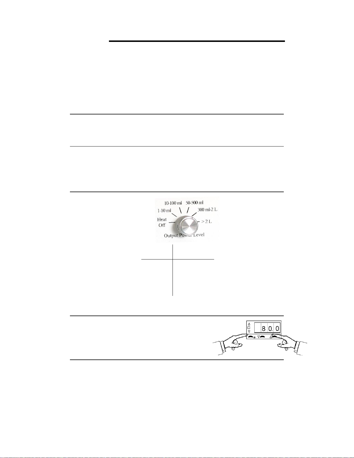
stable temperature control. To achieve stable control, the controller must 1) be set to the correct power level
(see Section 3.6) and, 2) be tuned to the heater being used. Tuning is the process that matches the control
characteristics of the controller to the heating characteristics of the heater. The controller is said to be tuned
to the heater when its memory is programmed with values describing how fast the heater warms up, cools
off, and how efficiently it transfers heat. For example, consider the difference between a heat lamp and a
hot plate. When electricity is applied to a heat lamp it begins to heat instantaneously, and when it's turned
off it stops heating instantaneously. In contrast, a hot plate takes several minutes to begin heating when
electricity is applied and even longer to stop heating when electricity is turned off. Your controller can
regulate both a heat lamp and a hot plate to 0.1oC. But, to do this it must be programmed with the time
constants describing how fast the heater heats and cools when electricity turns ON or OFF. These time
constants are called the tuning parameters.
Every type of heater has its own unique set of tuning parameters. For the controller to heat with
stability, it must have programmed with the tuning parameters for the heater currently being used. Prior to
shipment, tuning parameters were programmed into the controller that maximize heating performance for
laboratory heating mantles since these are the most common heaters used in research. Tuning is regulated
by 5 of the temperature meter’s user programmable functions. The correct value for these 5 functions can
be calculated and loaded manually, or the controller can do it automatically with its autotune feature.
When Should the Controller be Tuned? If the controller is tuned to one type of heater, heating mantles
for example, any size heating mantle can be used without the need to retune. When changing from
heating mantles to a different type of heater, an oven for example, the controller should be tuned with
values describing the oven’s heating characteristics. The effect of tuning is seen below. When the
controller is tuned for heating mantles, using it with any size heating mantle yields stable temperature
control (Plot 1), but poor control results when the same tuning parameters are used with an oven (Plot 2,
Curve 1). However, after tuning the controller to the oven, stable temperature control results (Plot 2,
Curve 2).

11
It’s important to understand that this controller isn’t a simple ON/OFF type controller (i.e. ON when below
the set point, OFF when above [though it can be made to work this way, see Section 3.12]). Rather it’s a
predictive controller. Based on the shape (slope) of the heating curve, the controller predicts (calculates) the
percent of power to apply to the heater now to control the shape of the heating curve minutes in advance.
The importance of the tuning parameters is that they are constants in the equation the temperature meter uses
to perform its predictive calculations. If the temperature meter is programmed with tuning parameters that
incorrectly describe the heater being used, poor temperature control will result. But, when the correct values
are loaded, temperature regulation of ± 0.1ois typically achieved.
Manual Tuning. Manual tuning is when the values of the 5 tuning parameters are determined manually
then entered into the temperature meter via the push buttons on the front of the controller. Experienced
users might prefer to manually tune the controller since this allows customization of the heating process.
Autotune. Autotune is a feature built into the temperature meter that automatically calculates the tuning
parameters (i.e. delay times, heating efficiency, etc.) for any type of heater. After the autotune
procedure is complete and the tuning parameters are determined, the controller loads them into its
memory for current and future use. Heating mantles are a special case and are covered in a separate
paragraph (Section 2.3).
2.2 Autotuning Procedure.
This procedure is not recommended for heating mantles (see Section 2.3). Perform this procedure
only on the controller channel in use.
1. Set the equipment up in the exact configuration it will be used. For example, to tune to a vacuum
oven, place the thermocouple in the room temperature oven and plug the oven into the controller.
If the oven (or heater) has its own thermostat or power control, turn both as high as they’ll go.
2. Set the controller to the appropriate power level (see Section 3.6). If tuning Channel 1, make sure
the timer switch is set so that heating is on (see Section 3.5). Turn the controller and heater on,
then enter the desired set point temperature. If the set point isn’t at least 30oC above ambient,
skip this procedure and go to the next procedure, “Autotuning the Controller for Very Fine
Control”
3. Press and hold in both the and buttons (for 3 seconds) on the front of the temperature meter
until the word “tunE” appears in the display then release both buttons.
4. Press the button (5 times) until “CyC.t” appears in the display (if you go past this setting,
press the ▼ button until you get back to it).
5. First, hold in the ‘*’ button, while holding in the ‘*’ button press the button. Continue to hold
both buttons in until the display reads “A --”, or “A ##” where “##” is some number.
6. Release the ‘*’ button and press the button until “tunE” once again appears in the display.
7. Press and hold the ‘*’ button and “tunE” will change to “off” to indicate that autotune is currently
off.
8. While holding in the ‘*’ button, press the button to change the display to “on”, then release
both buttons.
9. Press and hold both the and buttons (for 3 seconds) until the temperature appears in the
display. The controller is now in its autotune mode. While in autotune the display alternates
between “tunE” (for autotune) and the process temperature. When the autotune sequence is done
(this may take in excess of an hour) the controller stops displaying “tunE” and only displays the
process temperature. [To abort autotune manually, repeat steps 3, 8 and 9 except in step 8 press
the button until “off” is displayed].

12
The autotune sequence.
During autotune the controller heats
to 75% of the set point temperature
where it oscillates for several cycles
before loading the new tuning
parameters. After the tuning
parameters are loaded it heats to the
set point temperature. Tuning below
the set point prevents any damage
that might occur from overheating.
Autotuning the Controller for Very Fine Control.
This procedure is not recommended for heating mantles (see Section 2.3).
In the majority of cases, the procedure above results in stable temperature control with any heater. A
second version of the autotune routine is available and can be used when the heater is already at or close
to the set point, is being tuned at a temperature close to room temperature, or for very fine control in
demanding situations. If stable temperature control doesn’t result after performing the first autotune
routine, the procedure below should be performed. Before performing the ‘fine tune’ autotune
procedure, the ‘regular’ autotune procedure that precedes this should normally be performed.
1. Set the equipment up in the exact configuration it will be used. If the heater has its own
thermostat or power controls, turn both as high as they’ll go. With this procedure it’s not
necessary for the equipment to start at room temperature. This procedure can be performed at
any time and any temperature.
2. Set the controller to the appropriate power level (see Section 3.6). If tuning Channel 1, make sure
the timer switch is set so that heating is on (see Section 3.5). Turn the controller and heater on,
then enter the desired set point temperature.
3. Press and hold in both the and buttons (for 3 seconds) on the front of the temperature meter
until the word “tunE” appears in the display then release both buttons.
4. Press the button (5 times) until “CyC.t” appears in the display (if you go past this setting,
press the ▼ button until you get back to it).
5. First, hold in the ‘*’ button, while holding in the ‘*’ button press the button. Continue to hold
both buttons in until the display reads “A --”, or “A ##” where “##” is some number.
6. Release the ‘*’ button and press the button until “tunE” once again appears in the display.
7. Press and hold the ‘*’ button and “tunE” will change to “off” to indicate that autotune is currently
off.
8. While holding in the ‘*’ button, press the button to change the display to “At.SP”, then release
both buttons.
9. Press and hold both the and buttons (≈ 3 seconds) until the temperature appears in the
display. The controller is now in its autotune mode. While in autotune the display alternates
between “tunE” (for autotune) and the process temperature. When the autotune sequence is done
(this may take in excess of an hour) the controller stops displaying “tunE” and only displays the

13
process temperature. [To abort autotune manually, repeat steps 3, 8 and 9 except in step 8 press
the button until “off” is displayed].

14
Autotune Errors. The autotune routine can fail for several reasons. If it fails, the controller displays
the error message “tunE” “FAiL”. To remove this message turn the controller off for 10 seconds. Try
the procedure titled “Autotuning the Controller for Very Fine Control” above. If autotune fails again,
call and discuss your application with one of our engineers. A common problem when tuning at high
temperatures or with large volumes is for the heater to be underpowered. A more powerful heater may
be needed (contact J-KEM for assistance).
2.3 Tuning for Heating Mantles: A Special Case. This section gives special consideration to heating
mantles, since they’re the most commonly used heaters in research. Every heating mantle size has its own
optimum set of tuning parameters and if you wanted, the controller could be tuned (or autotuned) every time
a different size was used. However, this is cumbersome and is also unnecessary. Factory tests show that
there’s one set of tuning parameters that delivers good performance for all heating mantle sizes. These
tuning parameters were loaded into the controller at the factory prior to your receiving it. If you’re using a
heating mantle and none of the parameters have been changed or the controller hasn’t been autotuned since
you’ve received it, you’re ready to go. If the tuning parameters have been changed or the controller has been
autotuned and you want to go back to using heating mantles, J-KEM recommends that the tuning parameters
for heating mantles be loaded manually (i.e., don’t autotune to the heating mantle) by following the step-by-
step instructions given in Procedure 4 of Section 3.10.
2.4 Sensor Placement. Placement of the sensor is basically common sense. The sensor should be
positioned to sense the average temperature of the medium being heated. That means the thermocouple
should be shielded from direct exposure to the heater but not so distant that a rise in temperature isn’t sensed
by the controller within a reasonable period of time. Several examples follow that show the type of
consideration that should be given to sensor placement.
Use With:
Solutions
Place the sensor in the solution. Stir vigorously so that heat is homogeneously mixed
throughout the solution.
HPLC column heated
with a heating tape
Tape a thin wire thermocouple directly to the HPLC column. Place several layers of
paper over the thermocouple to insulate it from the heating tape (the thermocouple
should sense the column temperature, not the heater temperature). Wrap the HPLC
column completely with heating tape.
Oven
The thermocouple needs to be shielded from transient hot and cold air currents. Don’t
place the thermocouple near the heating coil or an air vent. A small thermocouple
(1/16” or 1/8” thermocouple) that responds rapidly to changes in air temperature is
better than a larger one.

15
Section 3: Operations Guide
3.1 Front Panel Description.
The Gemini controller has two independent temperature controllers in a single cabinet. The two
controllers are labeled Channel 1 and Channel 2. The controls for Channel 1 have no affect on the
operation of Channel 2 and visa versa.
J-KEM highly recommends that all users read Section 4.4 - How to Set Up a Reaction with J-KEM
Scientific’s Digital Temperature Controller prior to using the controller for the first time.
Controls for Channel One
1
2
3
45
6
7
8 - Power Receptacle (on back) 9
Controls for Channel Two
10
11
12 13 14 15 16 - Power Receptacle (on back)
1. Channel 1 Temperature Display. Shows the temperature
of the process connected to Channel 1 as the default
display. Shows the setpoint temperature (i.e. desired
temperature) when the ‘*’ button is held in.
2. Control Key When pressed, the display shows the set
point temperature. To decrease or increase the set point,
press the key (3) or key (3), while simultaneously
pressing the control key. The set point appears as a
blinking number in the display.
3. Down/Up Key Lowers or raises the setpoint when ‘*’
button (2) is simultaneously pressed.
4. On/Off Switch. WARNING: Due to the nature of solid
state relays, a small amount of output power (7.5 mA @
230 VAC; 1.8 watts) is present at outlet (8) even when the
controller is turned off. Take appropriate precautions to
avoid electrical shock.
5. Channel 1 Power Level. This knob is the interface to J-
KEM’s patented power control computer which limits the
maximum power delivered to the heater. See Sections 3.6
and 4.1.
6. Timer Display. Indicates the status of the timer. See
Section 3.5 for timer operation instructions.
7. Timer Mode Selector. Sets the operating mode of the
timer. See Section 3.5 for timer operation instructions.
8. Channel 1 Power Outlet. Plug only 230 VAC devices into
this outlet (see Section 3.2).
9. Channel 1 Temperature Sensor Input. Use the same type
of sensor probe as the sensor plug installed on the
controller (see Section 3.7). The correct sensor type will
10. Channel 2 Temperature Display. Shows the
temperature of the process connected to Channel 2 as
the default display. Shows the setpoint temperature
(i.e. desired temperature) when ‘*’ button is held in.
11. Control Key When pressed, the display shows the set
point temperature. To decrease or increase the set
point, press the key (12) or key (12), while
simultaneously pressing the control key. The set
point appears as a blinking number in the display.
12. Down/Up Key Lowers or raises the setpoint when ‘*’
button (11) is simultaneously pressed.
13. Channel 2 Power Level. This knob is the interface to
J-KEM’s patented power control computer which
limits the maximum power delivered to the heater.
See Sections 3.6 and 4.1.
14. On/Off Switch. WARNING: Due to the nature of
solid state relays, a small amount of output power (7.5
mA @ 230 VAC; 1.8 watts) is present at outlet (16)
even when the controller is turned off. Take
appropriate precautions to avoid electrical shock.
15. Channel 2 Temperature Sensor Input. Use the same
type of sensor probe as the sensor plug installed on the
controller (see Section 3.7). The correct sensor type
will have the same color plug as the input (15) on the
front of the controller.
16. Channel 2 Power Outlet. Plug only 230 VAC devices
into this outlet (see Section 3.2).

16
have the same color plug as the input (9) on the controller.

17
3.2 Heater Restrictions. Each channel of the controller can individually deliver up to 10 amps of current at
230 VAC, but the combined total current from Channels 1 & 2 can not exceed 15 amps. These current
ratings are limited to resistive loads (heating mantles, hot plates, ovens, etc.). Use only resistive loads that
are safely operated at 230 VAC and require less than 10 amps or damage to the controller and a safety
hazard may result.
•Do not plug oil baths into your controller. Oil baths are not 230 VAC devices and become a fire
hazard unless properly connected to the controller. (See Appendix for an application note
describing the use of oil baths with this controller). Ask about J-KEM’s new 400 series controllers for
use with oil baths.
3.3 Ramp-to-Setpoint & Soak Feature. A new feature of J-KEM’s controllers called ‘Ramp-To-Setpoint’
allows you to enter a specific heating rate (e.g., heat to 120oC at a rate of 5oC/Hour), a second feature
called ‘Soak’ then lets you specify how long to stay at that temperature before turning off.
Examples of Program Ramps
The controller is shipped with the Ramp-to-Setpoint feature OFF, the user must specifically turn Ramp-to-
Setpoint ON. When Ramp-to-Setpoint is OFF, the controller heats to the entered setpoint at the fastest rate
possible. When Ramp-to-Setpoint is ON, the controller heats at the user entered ramp rate.
The Ramp-to-Setpoint feature and its associated parameters are turned on and set in the controller’s
programming mode. The parameters of importance are:
SPrr SetPoint Ramp Rate. Allowable Values: 0 to 9990 deg/Hr.
This specifies the desired rate of heating (cooling). Note, this parameter specifies the desired rate of heating
(cooling), but in cases of extremely high ramp rates the reaction will not actually heat faster than the power
of the heater will allow.
SPrn SetPoint Ramp Run. Allowable Values: ON, OFF, Hold
This parameter turns the Ramp-to-Setpoint feature ON or OFF. During an active run, if this parameter is
set to ‘Hold’, the setpoint ramp stops and holds at its’ current value. This continues until the parameter is
set to ON or OFF. When set to OFF, the values in SetPoint Ramp Rate and Soak Time are ignored.
SoAK Soak Time. Allowable Values: “- -”, 0 to 1440 min.
This specifies the amount of time to soak at the setpoint after the setpoint temperature ramp is complete. A
setting of “- -”causes the controller to remain at the final setpoint indefinitely. A numeric value causes the

18
controller to stay at the setpoint for the entered time and then turn power to the heater off after the time
expires.
Important Points to Know
1. While the Ramp-to-Setpoint feature is activated, the display alternates between the current reaction
temperature and the word “SPr” to indicate that a “SetPoint Ramp” is active.
2. If this controller is equipped with a digital 100-hour timer, the digital timer and the Ramp-to-Setpoint
feature are completely independent of each other. For example, if the digital timer is set to turn heating
OFF after 5 hours, heating is turned off even if a ramp step is in progress. Likewise, if a Soak time
turns heating off after 3 hours and the digital timer is set to turn heating off after 10 hours, the digital
timer has no effect since the expired Soak time already has turned heating off.
3. Once the Ramp-to-Setpoint feature is activated in programming mode, it remains on until it’s
deactivated in programming mode. The Ramp-to-Setpoint feature remains activated even when power
is turned off, and then turned back on.
4. Setting a ramp rate in the digital controller does not guarantee that the reaction itself will ramp at the
entered value, since the rate of heating is dependent on the power of the heater. Setting a ramp rate in
the controller only guarantees that the controller’s setpoint will be changed at the entered rate. For the
reaction temperature to increase temperature at the specified rate, the heater must have sufficient power
to heat at the entered rate. This is a critically important point, the user must understand that the
electronic setpoint in the controller will ramp at the entered rate, but the controller cannot force a heater
to heat a reaction faster than it’s capable of doing. For example, see the plots below.
Plot 1 –This plot uses a heating mantle to ramp temperature in reaction from 20 to 80C in 60 minutes. The
reaction temperature closely matches the setpoint of the controller because heating mantles have enough
power to heat a typical reaction at the modest heating rate of 1 degree per minute.
Plot 2 –In this example, the ramp rate is set to 600 C/ hour, or 10 C per minute. The controller ramps the
setpoint at the requested rate, but the reaction temperature does not match the ramp, because the heater does
not have enough power to heat the reaction as such a high rate. Every time the reaction temperature does
not match the entered ramp rate, it’s because the heater has insufficient power to heat at the requested rate.
The only solution to this situation is 1) use a more powerful heater, or 2) lower the ramp rate to a value that
does not exceed the heaters maximum heating rate. The controller has no influence over a heater that has
insufficient power to heat at the entered ramp rate.
Plot 1 Plot 2
00.2 0.4 0.6 0.8 1.0 1.2
Hours
Controller Setpoint
Reaction Temperature
0
40
80
00.2 0.4 0.6 0.8 1.0 1.2
Hours
Controller Setpoint
Reaction Temperature
0
100
200
300

19
This plot shows actual data.
The green line is the temperature profile
when ramping is not used and the reaction
heats to the setpoint as normally. The red
and blue lines are the result of a ramp run.
The red line is the setpoint being ramped at a
rate of 2C/min.
The blue line is the reaction temperature that
results from this ramp.
Two features of this plot are characteristics of
ramp runs. 1) At the start of a run, the
reaction temperature almost always exceeds
the temperature of the ramped setpoint, and 2)
ramp runs overshoot the final setpoint value
by 4-5 C.
Activating & Programming the Ramp-to-Setpoint Feature
tunE CyC.tdACder.tint.tbAnd oFSt SEt.2SoakSPrnSPrrsp.lk CyC.2bnd.2
This is the order of controller parameters on Level 1 of the controller, when the controller is placed into programming mode (Step 1)
below.
1.
Before starting a new ramp, the controller must have the ramping feature turned off. Verify that the ramping feature is
turned off by entering programming mode and checking verifying this before continuing.
To enter programming mode, press and hold in both the ▲ and ▼ keys on the front of the temperature meter until the word
“tunE” appears in the display, then release both keys.
Now press the ▲ key (9 times) until the word “SPrn” appears in the display, then release all keys. The display on the
controller will alternate between “SPrn” and the word ON or OFF. If the word OFF is displayed, then exit programming
mode and proceed to Step 2. If the work ON is displayed, then hold in the ‘*’ key and press the ▼ key once to change the
display from ON to OFF, then release all keys. To exit programming mode, press and hold in both the ▲ and ▼ keys
until the temperature appears in the display, then release both keys.
2.
Note the current reaction temperature displayed by the temperature controller. Enter this temperature into the controller
as a new setpoint. For example, if the current reaction temperature is 22.5 C, then set the controller’s setpoint to 22.5 C .
3.
Press and hold in both the ▲ and ▼ keys on the front of the temperature meter until the word “tunE” appears in the
display, then release both keys.
4.
Press the ▲ key (8 times) until the word “SPrr” appears in the display.
This is where the ramp rate in units of degrees/hour is entered. First hold in the ‘*’ key, then while holding in the *’
key press the ▼ or ▲ key until the desired ramp rate appears in the display, then let go of all the keys. Units are in
degrees/hour, so if you want a ramp rate of 2C/min, then enter a value of 120.
5.
Press the▲ key once and the word “SPrn” will appear in the display.
This function turns the ramping feature ON or OFF. First hold in the ‘*’ key, then while holding in the *’ key press
the ▼ or ▲ key until the display shows ON (to start a ramp) or OFF (to terminate a ramp), then let go of all the keys.
6.
Press the ▲ key once and the word “SoaK” will appear in the display.
This is where the soak time is entered in units of minutes. A soak time of ‘ -- ‘ means to ‘soak forever’ (this setting
is one below ‘0’). First hold in the ‘*’ key, then while holding in the *’ key press the ▼ or ▲ key until the desired
time appears in the display, then let go of all the keys. If a soak time is set, the controller display will alternate
between showing the current reaction temperature and the word “StoP” when the soak time has expired to indicate
that power has been turned off.
7.
To exit programming mode, press and hold in both the ▼ and ▲ keys until the temperature appears in the display, then
release both keys.
Deactivating the Ramp-to-Setpoint Feature
1.
Press and hold in both the ▲and ▼ keys on the front of the temperature meter until the word “tunE” appears in the
display, then release both keys.
2.
Press the ▲ key (9 times) until the word “SPrn” appears in the display.
This function turns the ramping feature ON and OFF. First hold in the ‘*’ key, then while holding in the *’ key press
the ▼ or ▲ key until OFF appears in the display, then let go of all the keys.
3.
To exit programming mode, press and hold in both the ▲ and ▼ keys until the temperature appears in the display, then
release both keys.
Reaction temperature exceeds the
value of the ramped setpoint.
Ramp runs typically over-shoot
the setpoint by a greater amount
than standard runs do.

20
3.4 Over Temperature Protection Circuit.
NOTE: The controller is shipped with the Over
Temperature Protection Circuit DISABLED. To
activate this circuit for either or both channels,
follow Procedure 3 below.
Both channels of the Gemini are equipped with over temperature protection circuits. This circuit turns off
heating and sounds an audible alarm if the process temperature for Channel 1 and/or Channel 2 exceeds the
set point by 5 degrees. The high temperature limit (i.e. the limit that must be exceeded to trigger this
circuit) is factory set to 5 degrees for both channels, but can be changed or enabled or disabled as outlined in
the procedures below. The over temperature protection circuit for Channels 1 & 2 are independent of each
other. A temperature limit entered into the temperature meter controlling Channel 1 has no affect on
Channel 2 and visa versa.
Procedure 1.
To Change the Number of Degrees that the Reaction Temperature Must
Exceed the Set Point to Trigger the Over Temperature Alarm, Perform this Procedure.
1.
Press and hold in both the and keys on the front of the temperature meter for the Channel you want to change until the word
“tunE” appears in the display, then release both keys.
2.
Press the key until “SEt.2” is showing in the display.
First hold in the ‘*’ key, while holding in the ‘*’ key press the or keys until the desired temperature limit is showing in the display,
then let go of all the keys.
3.
Press and hold in both the and keys until the temperature is showing again.
Procedure 2.
To Permanently Disable the Over Temperature Circuit, Perform this Procedure.
1.
Press and hold in both the and keys on the front of the temperature meter for the Channel you want to change until the word
“tunE” appears in the display, then release both keys.
2.
Press the key until “LEVL” is showing in the display.
3.
Hold in the ‘*’ key, while holding in the ‘*’ key press the key until “2” is showing in the display, then let go of all the keys.
4.
Press the key until “SP2.A” is showing in the display.
5.
Hold in the ‘*’ key, while holding in the ‘*’ key press the key until “nonE” is showing in the display, then let go of all the keys.
6.
Press the key until “LEVL” is showing in the display.
7.
Hold in the ‘*’ key, while holding in the ‘*’ key press the key until “3” is showing in the display, then let go of all the keys.
8.
Press the key until “rEU.d” is showing in the display.
9.
Hold in the ‘*’ key, while holding in the ‘*’ key press the key until “1r.2d” is showing in the display, then let go of all the keys.
10.
Press and hold in both the and keys until the temperature is showing again. When you do this, the alarm will sound.
11.
Increase the set point by any amount by first holding in the ‘*’ key, then while holding in the ‘*’ key press the key.
Procedure 3.
To Enable the Over Temperature Protection Circuit, Perform this Procedure.
1.
Press and hold in both the and keys on the front of the temperature meter for the Channel you want to change until the word
“tunE” appears in the display, then release both keys.
2.
Press the key until “LEVL” is showing in the display.
3.
Hold in the ‘*’ key, while holding in the ‘*’ key press the key until “2” is showing in the display, then let go of all the keys.
4.
Press the key until “SP2.A” is showing in the display.
5.
Hold in the ‘*’ key, while holding in the ‘*’ key press the key until “dU.hi” is showing in the display, then let go of all the keys.
6.
Press the key until “LEVL” is showing in the display.
7.
Hold in the ‘*’ key, while holding in the ‘*’ key press the key until “3” is showing in the display, then let go of all the keys.
8.
Press the key until “rEU.d” is showing in the display.
9.
Hold in the ‘*’ key, while holding in the ‘*’ key press the key until “1r.2r” is showing in the display, then let go of all the keys.
10.
Press the key until “LEVL” is showing in the display.
11.
Hold in the ‘*’ key, while holding in the ‘*’ key press the key until “1” is showing in the display, then let go of all the keys.
12.
Press the key until “SEt.2” is showing in the display.
13.
Hold in the ‘*’ key, while holding in the ‘*’ key press the or key until “5.0” is showing in the display, then let go of all the keys.
14.
Press and hold in both the and keys until the temperature is showing again.
Table of contents
Popular Laboratory Equipment manuals by other brands

Endecotts
Endecotts M100 user guide

Fisher Scientific
Fisher Scientific Fisherbrand 88861027 Operation manual

VistaLab
VistaLab Ovation 9060-5009 Replacement instructions

Promega
Promega Maxprep AS9100 operating manual

Infinite
Infinite Transtector TEF14-C5-TE12 user manual

vita
vita V60 i-Line operating manual