CARVIN DCM1500 User manual

CAUTION
RISK OF ELECTRIC SHOCK
DO NOT OPEN
SAFETY INSTRUCTIONS (EUROPEAN)
The conductors in the AC power cord are colored in accordance with the following code.
GREEN & YELLOW—Earth BLUE—Neutral BROWN—Live
U.K. MAIN PLUG WARNING: A molded main plug that has been cut off from the cord is
unsafe. NEVER UNDER ANY CIRCUMSTANCES SHOULD YOU INSERTA DAMAGED
OR CUT MAIN PLUG INTO A POWER SOCKET.
IMPORTANT! FOR YOUR PROTECTION, PLEASE READ THE FOLLOWING:
WATER AND MOISTURE: Appliance should not be used near water (near a bathtub, washbowl,
kitchen sink, laundry tub, in a wet basement, or near a swimming pool, etc). Care should be taken
so that objects do not fall and liquids are not spilled into the enclosure through openings.
POWER SOURCES: The product should be connected to a power supply only of the type described
in the operating instructions or as marked on the appliance.
GROUNDING OR POLARIZATION: Precautions should be taken so that the grounding or polar-
ization is not defeated.
POWER CORD PROTECTION: Power supply cords should be routed so that they are not likely
to be walked on or pinched by items placed upon or against them, paying particular attention
to cords at plugs, convenience receptacles, and the point where they exit from the appliance.
SERVICING: The user should not attempt to service the appliance beyond that described in the
operating instructions. All other servicing should be referred to qualified service personnel.
FUSING: If your unit is equipped with a fuse receptacle, replace only with the same type fuse.
Refer to replacement text on the unit for correct fuse type.
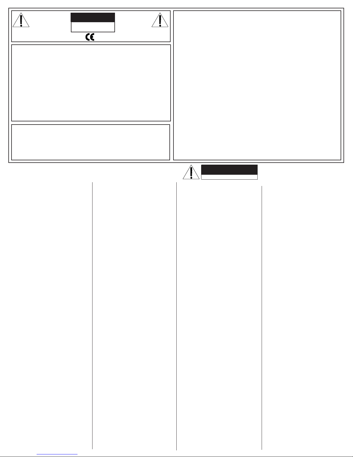
REFER SERVICING TO QUALIFIED SER-
VICE PERSONNEL! THIS UNIT CON-
TAINS HIGH VOLTAGE INSIDE!
CAUTION
RISK OF ELECTRIC SHOCK
REPLACEMENT PARTS LIST FOR DCM AMPS
This symbol is intended to
alert the user to the pres-
ence of uninsulated “dan-
gerous voltage” within the
product’s enclosure that may be of suf-
ficient magnitude to constitute a risk of
electric shock to persons.
This symbol is
intended to alert the
user to the presence of
important operating
and maintenance (servicing) instruc-
tions in the literature accompanying
the appliance.
LIMITED WARRANTY
Your Carvin product is guaranteed against failure for 3 YEARS unless otherwise stated.
Carvin will service and supply all parts at no charge to the customer providing the unit
is under warranty. Shipping costs are the responsibility of the customer. CARVIN DOES
NOT PAY FOR PARTS OR SERVICING OTHER THAN OUR OWN. A COPY OF THE ORIG-
INAL INVOICE IS REQUIRED TO VERIFY YOUR WARRANTY. Carvin assumes no respon-
sibility for horn drivers or speakers damaged by this unit. This warranty does not cover,
and no liability is assumed, for damage due to: natural disasters, accidents, abuse, loss
of parts, lack of reasonable care, incorrect use, or failure to follow instructions. This war-
ranty is in lieu of all other warranties, expressed or implied. No representative or person
is authorized to represent or assume for Carvin any liability in connection with the sale
or servicing of Carvin products.
CARVIN SHALL NOT BE LIABLE FOR INCIDENTAL OR CON-
SEQUENTIAL DAMAGES.
When RETURNING merchandise to the factory, you may call for a return authoriza-
tion number. Describe in writing each problem. If your unit is out of warranty, you
will be charged the current FLAT RATE for parts and labor to bring your unit up to fac-
tory specifications.
MAINTAINING YOUR EQUIPMENT
Avoid spilling liquids or allowing any other foreign matter inside the unit. The panel of
your unit can be wiped from time to time with a dry or slightly damp cloth in order to
remove dust and bring back the new look.
As with all pro gear, avoid prolonged use in
caustic environments (salt air). When used in such an environment, be sure the ampli-
fier is adequately protected by rack, covers, etc..
03-00220 2 EACH INSLTR MICA .0030".450"X .65"
03-00223 2 EACH INSLTR MICA .0030"1.37"X .65"
03-00450 1 EACH INSLTR 9.125x1.5x.01" SGL ADHV
03-00475 1 EACH SPACER PAD .1X .4X .75 W/ADHSV
03-00503 8 EACH INSULATOR .36X .36X .20" 85deg
03-82061 1 EACH CABLE TIE 14.5Lx .19Wx 2" BNDL
03-92521 6 EACH STANDOFF LED .925 x .215 T1
USE ON D2,D3,D181,D180,D31,D32
05-85622 1 EACH CABLE ASSY, 5C 220MM
06-10028 24 EACH MS PPH 4-40X .500 ZINC TYPE F
06-40050 7 EACH TERMINAL VERT MALE PC MTG .250
QC1,QC2,QC3,QC4,QC5,QC6,QC7
07-01602 1 EACH KNOB "6" 6x6x9.7mm GREY CAP S3
07-01603 3 EACH KNOB "6L" 6x6x17.4mm GREY CAP
S1,S2,S4
12-00880 1 EACH HEATSINK 8"L 1pc FAN MOUNTED
15-00105 2 EACH COIL AIR 1.5uH 14AWG L100,L200
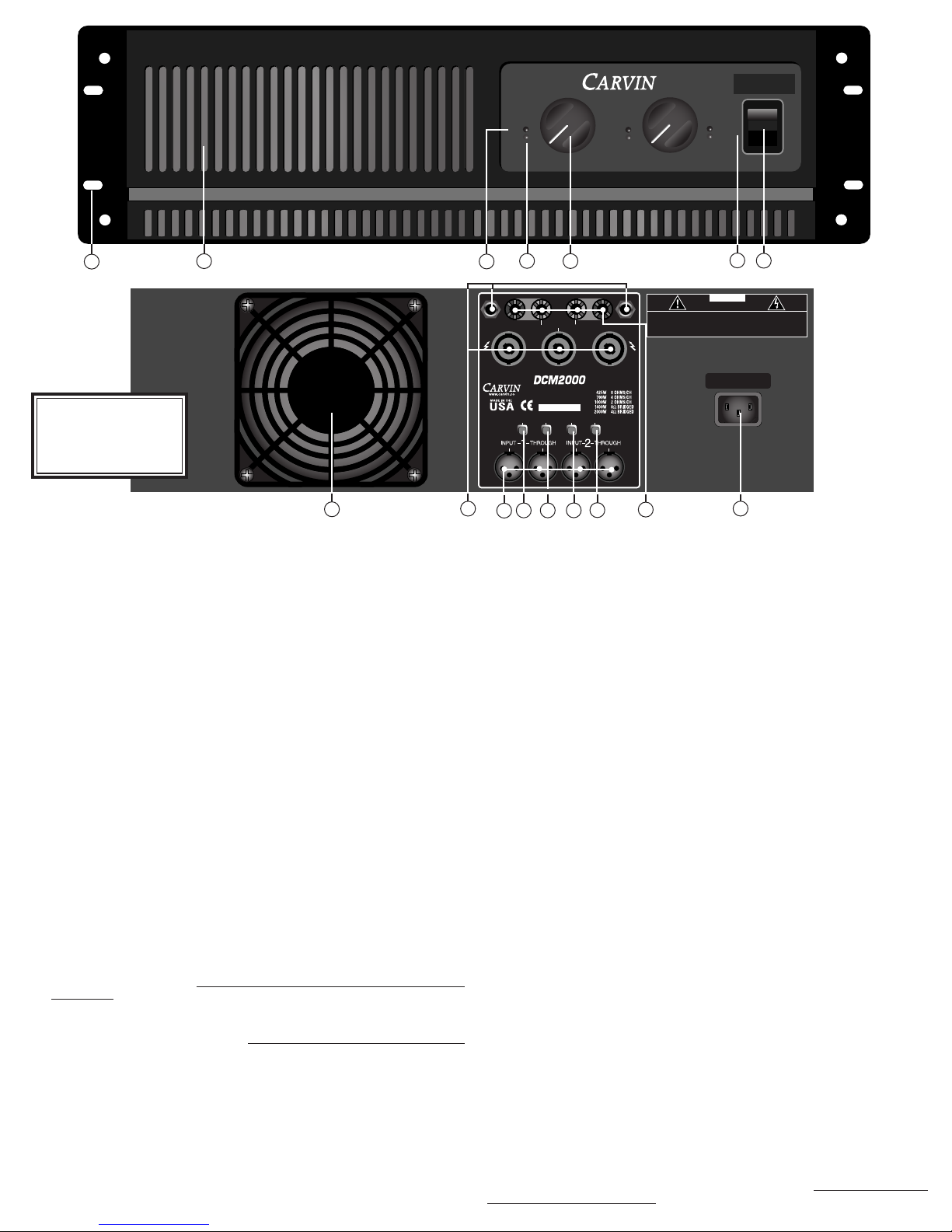
21-31100 1 EACH RECEPTACLE AC W/FAST-ON CHASS PL1
21-40000 2 EACH XLR FEMALE CONNECTOR W/O GRND
J100,J200
21-40001 2 EACH XLR MALE CONNECTOR J1,J2
21-45000 3 EACH SPEAKON 4-POLE PCMTG #NL4MD-V
J3,J103,J203
21-52345 2 EACH JACK .250 PHONE MONO STEEL
J105,J205
23-03529 2 EACH FUSEHOLDER CLIPS 3AG VERT MTG
F1
23-08604 3 EACH CONNECT HEADER .086" 4 PIN H6B H1 H6A
23-08605 1 EACH CONNECT HEADER .086" 5 PIN H5
23-08612 1 EACH CONNECT HEADER .086" 12 PIN H7
23-10002 3 EACH CONNECT HEADER .100" 2 PIN H4,H8,H9
23-11010 6 EACH CONNECT HEADER 10 PIN STRAIGHT
H1A,H1B,H2A,H2B,H3A,H3B
25-02201 4 EACH SWITCH DPDT PUSH PC MTG LOCKNG
S1,S2,S3,S4 30-
02000K 1 EACH PCB CARD MAIN DCM1500/2000
41-47322 3 EACH CAP MYLR .0470UF 250VAC BOX
C19,C20,C21
42-10312 4 EACH CAP ELEC 10,000 MFD 100V 20%
C115,C116,C215,C216
44-13520 2 EACH JUMPER PCB 20AWG .350" X .175" B1,B3
45-25152 4 EACH CAP CERM 250PF 500VOLT 5%
C106,C107,C206,C207
46-10412 2 EACH CAP POLY .1000UF 100VOLT 10%
C117,C217
46-47312-1 2 EACH CAP POLY .0470UF 100V 10%PREP
C127,C227
47-10235 4 EACH CAP ELEC 1,000 MFD 35V 20%
C1,C2,C8,C12
47-22151 1 EACH CAP ELEC 220 MFD 50VOLT 10% C18
47-47125 1 EACH CAP ELEC 470 MFD 25VOLT 20% C7
49-10412 2 EACH 0.1UF SMT 5% CERAMIC 0805 C10,C13
49-22035 13 EACH SMT CAP 22uF 35v ELECTROLITIC
C15,C16,C17,C102,C120,C124,C126,
C181,C202,C220,C224,C226,C281
49-22212 1 EACH 0.0022UF SMT 10% FILM 0805 50V C14
49-27052 9 EACH 27 PF SMT 5% CERAMIC 0805
C100,C101,C103,C104,C200,C201,
C203,C204,C280
49-39052 2 EACH 39PF SMT 5% CERAMIC 0805 C123,C223
49-47312 6 EACH 0.047UF SMT 10% FILM 0805 50V
C3,C4,C9,C11,C105,C205
49-82052 2 EACH 82PF SMT 5% CERAMIC 0805 C121,C221
52-10015 1 EACH RES 10.00 OHM .50W 5% CARBON R27
55-03300 24 EACH RES .33 OHM 5W 5% SB VERT R142,R143,
R144,R145,R146,R147,R148,R149,R150,
R151, R152,R153,R242,R243,R244,R245,
R246,R247,R248,R249, R250,R251,
R252,R253
55-05025 4 EACH RES 5.00 OHM 5W 5% SB VERT
R120,R121,R220,R221
55-30035 2 EACH RES 3.00KOHM 5W 5% SB WIRE R42,R43
56-35010 2 EACH RES 350.00 OHM 10W 10% SB SDOF
R44,R45
58-00035 2 EACH 0.0 SMT JUMPER 1206 R181,R282
58-10025 2 EACH 100.5 SMT .25W 1206 1% R128,R228
58-10035 9 EACH 1K SMT .25W 1206 1% R8,R15,R22,R34,
R111,R129,R211,R229,R187
58-10045 24 EACH 10K SMT .25W 1206 1% R5,R13,R19,R28,
R30,R35,R100,R101,R113,R154,R156,
R200,R201,R213,R254,R256,R183,
R185,R190 R283,R285,R290,R189,R289
58-10055 7 EACH 100K SMT .25W 1206 1%
R21,R114,R157,R214,R257,R184,R284
58-10065 2 EACH 1M SMT .25W 1206 1% R115,R215
58-15025 2 EACH 150ohm SMT .50W 1206 1% R141,R241
58-15035 1 EACH 1.5K SMT .25W 1206 1% R18
58-15045 9 EACH 15K SMT .25W 1206 1% R23,R102,R103,
R202, R203, R112, R212,R155,R255
58-15055 3 EACH 150K SMT .25W 1206 1% R11,R12,R260
58-22035 5 EACH 2.2K SMT .25W 1206 1% R1,R137,R237,
R191,R291
58-22045 9 EACH 22K SMT .25W 1206 1% R26,R29,R106,
R107, R125,R130,R206,R230,R225
58-22055 6 EACH 220K SMT .25W 1206 1% R31,R119,
R140,R219,R240,R186
58-27025 6 EACH 270.5 SMT .25W 1206 1% R108,R131,
R132,R208,R231,R232
58-47025 2 EACH 470.5 SMT .25W 1206 1% R24,R32
58-47035 9 EACH 4.7K SMT .25W 1206 1% R2,R7,R10,
R14,R188,R288,R135,R235,R20
58-47045 6 EACH 47K SMT .25W 1206 1% R33,R126,
R226,R180,R280,R281
58-47055 6 EACH 470K SMT .25W 1206 1% R16,R25,
R109,R209, R110, R210
58-68035 2 EACH 6.8K SMT .25W 1206 1% R104,R204
58-68045 1 EACH 68K SMT .25W 1206 1% R17
58-92201 8 EACH 22 SMT 1W 2512 20% R38,R39,R40,
R41,R133,R134,R233,R234
58-95102 8 EACH 510 SMT 1W 2512 5% R6,R9,R36,
R37,R127,R136,R227,R236
60-00014 1 EACH TRANS MPSA14 DRLNGTN NPN T0-92 Q1
60-15032 2 EACH TRANS MJE15032 NPN T0-220
Q107,Q207
60-15033 2 EACH TRANS MJE15033 PNP T0-220 Q108,Q208
60-21193-1 *STD 12 EACH TRNS BIPOLAR MJL21193-PREPPED
Q109,Q110,Q111,Q112,Q113,
Q114,Q209,Q210,Q211,Q212, Q213,Q214
60-21194-1 *STD 12 EACH TRNS BIPOLAR MJL21194-PREPPED
Q115,Q116,Q117,Q118,Q119,Q120,
Q215,Q216,Q217,Q218, Q219,Q220
60-31000 3 EACH BIPOLAR PWR TIP31C NPN 3A 100V
Q4,Q106,Q206
60-35041 2 EACH RECTIFIER BRIDGE 35AMP/400V PC
BR100,BR200
60-50200 4 EACH DIODE GEN REC 1N5402 3A 200V
D107,D108,D207,D208
60-50253 2 EACH OPTO ISOLATOR VACTROL AXIAL
OP100,OP200
60-75320 3 EACH LED RED DIFFUSED 3MM T-1.00
D2,D31,D181
60-75330 2 EACH LED GREEN DIFFUSED 3MM T-1.00
D32,D180
60-75340 1 EACH LED YELLOW DIFFUSED 3MM T-1.00
D3
60-78150 1 EACH REGULATOR VOLTAGE 15 +V 1 AMP
VR1
60-79120 1 EACH REGULATOR VOLTAGE 12 -V 500mA
Q7
60-79150 1 EACH REGULATOR VOLTAGE 15 -V 1 AMP
VR2
61-04733 1 EACH DIODE ZENER 1N4733A 5.1V 1W
Z1
61-40030 1 EACH DIODE RECT GEN 1N4003 200V 1A
D24
62-00014 2 EACH MMBTA14 SOT-23 SMT Q100,Q200
62-06001 7 EACH DIODE ULTRA FAST 600V 1A SMA
D11,D12,D4,D5,D6,D7,D9
62-19140 24 EACH 1N914 HI SPD SMT 250mW DIODE
D1,D8,D10,D13,D14,D19,D20,
D21,D22,D23,D100,D104,D106,
D200,D204,D206,D15,D16,D25,
D26,D27,D28,D29, D30
62-20430 4 EACH NJM2043SMT(TESTED) DUAL HFREQ
A1,A5,A100,A200
62-29010 1 EACH NJM2901SMT SNGLE SUPPLY A3
62-45650 3 EACH NJM4565 SMT DUAL HI FREQ A6,A7,A2
62-54001 5 EACH MMBT5401LT1 PNP SOT-23 SMT
Q2,Q3,Q6,Q101,Q201
62-55500 5 EACH MMBT5550 NPN SOT-23
Q5,Q102,Q202,Q8,Q9
70-05712 4 EACH RELAY SPDT 12A@120VAC/24V COIL
K100,K200,K1,K2
70-22125 1 EACH FUSE MDA 25.00A SLOW 6.35X32MM
71-09251 2 EACH POT 9 D-P 25F B10K THREAD BSH
P100,P200
71-24450 2 EACH POT VERT TRIMMER 500ohm
P101,P102

CARVIN ENGINEERING DATA OPERATING MANUAL
The DCM Series professional amps are designed utilizing Carvin’s 35
years of experience in power amp technology. They meet or exceed every
standard for professional amplification. Their powder coated steel face
plates, large recessed knobs and heavy-duty steel chassis reflect the man-
ufacturing quality within. The DCM professional amps are available in
five different models and carry the CE approval for world-wide use.
PURE—TRANSPARENT SOUND
Carvin considers the sound of an amp equally important as its reliability. To
insure pure, uncolored sound, we designed one of the fastest responding power
amps on the market today. High slew rates of 50v/µs deliver superb transient
response. High frequencies are transparent and open—even at extreme levels.
Linear feedback circuits reduce distortion to near the theoretical zero limit pre-
venting any type of harshness which would lead to ear fatigue. The DCM Series
amps deliver flat, transparent, unaltered sound—especially important to the studio
user. And you can drive any type of reactive loads, including 70V transformer
distribution systems. These amps are designed to deliver non-stop, continuous
power and are completely protected from heat and short circuits.
ULTRA RUGGED FOR TOURING
Every chassis is made from heavy-duty 16 gauge steel that is plated before
being painted to prevent rust. All internal cabling is neatly tied and harnessed.
Every circuit card is FR-4 MILITARY SPEC, double-sided, through-hole plated,
fire retardant glass epoxy. This insures that the solder flows on the top, bottom
and through each hole of every component preventing components from shak-
ing loose—even through constant tour use. XLR connectors, heavy-duty power
switches, recessed knobs and machined front panels give the DCM amps a
“tank-like” ability to handle rough, touring transport.
TOTALLY MODULAR
With the DCM Series, Carvin brings you totally modular construction. If you
ever need an I/O (input/output) connector card because a connector wore-out,
just unplug it and re-install the replacement card in minutes. You don’t have
to de-solder anything. This applies to every aspect of the DCM Series amps
including the power supply, power cards, heat sinks and fans. Everything is
connected by heavy-duty AMP™ and MOLEX™ type connectors for easy replace-
ment—even the Toroid transformer is a total plug-in.
HEAVY-DUTY COOLING
Carvin offers up to 30% more cooling than comparable amps rated at the same
wattage. This means that the DCM Series are thermally “over-engineered” to be
sure heat will never be a concern. Even outdoor concerts in direct sunlight will
not cause thermal shut down. Carvin uses precision 6063 T-5 aluminum high
ratio heat sinks that are extruded for massive amounts of cooling. A high efficiency,
multi-speed fan cools your amp quietly even when moving air at up to 115 CFM!
LIGHTER WEIGHT
For some companies weight reduction means cost reduction. Carvin however,
uses expensive TOROID transformers to reduce weight. Toroids deliver mas-
sive amounts of “on demand” current for continuous 2 ohm operation. This
gives the power supply a solid foundation yielding more headroom for the largest
subwoofer application. Not only do toroids deliver high current, but they are
known for reducing stray magnetic fields eliminating hum & noise. This is espe-
cially important for the recording industry.
DCM POWER AMP SPECIFICATIONS:
MODEL DCM1500 DCM2000
Bridged RMS Continuous
4Ω, (20-20k Hz, <1.0%) 1500w 2000w
8Ω, (20-20k Hz, <1.0%) 1000w 1400w
Both Channels RMS Continuous
2Ω(20-20k Hz, <1.0%) 750/750w 1000/1000w
4Ω(20-20k Hz, <1.0%) 500/500w 700/700w
8Ω(20-20k Hz, <1.0%) 300/300w 450/450w
THD (Typical—1/2 power): 0.03% 0.03%
Damping Factor: >450 >500
Slew Rate: bridged mode >50v/µs >50v/µs
Sensitivity: (4Ω, Vms) 1.0 V 1.0 V
Signal to Noise Ratio: Above 100dB
Frequency Response: ±0.5 dB, 20 Hz to 20kHz
(±1.5 dB, 10 Hz & 40 kHz)
Input Impedance: >20K Ω, balanced
Protection Circuits: Short Circuit • No Load Protection • SpeakerGuard™ • Thermal Shut-Off • Mute On/Off
Control and Indicators:
Front: Power switch • Recessed 41 detent attenuators • Signal LED • Clip LED • Protect LED • Power Indicator
Rear: Ground Lift (each channel) • Parallel Input Switch • Speaker Output Bridge Switch • Limiters
IN/OUT Switch • Input Connectors: Two each; Balanced XLR male/female • Speaker Output
Connectors: Dual heavy-duty binding posts, two 1/4” & three (one for bridge use only) Twist-lok
Dimensions: 5 1/4" High x 19" Wide x 10" Depth (3-space)
Net Weight: DCM1500: 32 lbs. DCM2000: 40 lbs.
76-20000C 0901
12340 World Trade Drive, San Diego, CA 92128
800.854.2235 www.carvin.com
For your records, you may wish to record the following information.
Serial No._____________________ Invoice Date_______________
RECEIVING INSPECTION—read before getting started
INSPECT YOUR UNIT FOR ANY DAMAGE which may have occurred during shipping. If any
damage is found, please notify the shipping company and CARVIN immediately.
SAVE THE CARTON & ALL PACKING MATERIALS. In the event you have to re-ship your unit,
always use the original carton and packing material. This will provide the best possible protec-
tion during shipment. CARVIN and the shipping company are not liable for any damage caused
by improper packing.
SAVE YOUR INVOICE. It will be required for warranty service if needed in the future.
SHIPMENT SHORTAGE. If you find items missing, they may have been shipped separately.
Please allow several days for the rest of your order to arrive before inquiring.
RECORD THE SERIAL NUMBER on the enclosed warranty card or below on this manual
for your records. Keep your portion of the card and return the portion with your name and
comments to us.
DCM1500 & DCM2000 POWER AMPS
DISTORTION-FREE LIMITERS
The purpose of a limiter is to hold down peaks so the amp won’t distort even
with extra hot input signals (this protects your expensive speakers). In addition,
a well designed limiter can increase your amp’s average output as much as 3 db.
Part of Carvin’s design uses the more expensive, distortion-free linear “opto iso-
lators”. Unlike amps that use FET controlled limiters which can inject small amounts
of distortion, the DCM Series limiters keep your sound pure and uncolored!
FRONT PANELS & CONNECTING UP
The DCM Series feature front panel signal, peak and protect LEDs which let you
monitor the status of the amp. Balanced XLR input and through jacks are used to
eliminate hum & noise. Speaker outputs features Twist-Lok connectors, plus 1/4”
jacks & heavy-duty binding posts that accept up to 50 amp #7 speaker wires.
The rear professional accessory group offers a GROUND switch to remove the
chassis ground from the XLR input. A Parallel input switch connects the inputs
of both channels together eliminating Y connectors and allowing amp patching
in multiple amp systems. The accessory group also features a recessed bridge
mode switch for delivering full power into a 4Ωload or 70V distribution system
and a limiter ON/OFF switch that gives you the choice of using the internal limiter
circuitry.
DCM1500, DCM2000

PROTECT
∞
50
30
22
19
1717
15
13
12 11 10 98
7
6
5
4
3
2
1
0 dB0 dB
DCM2000
1000 Watt Power Amp
CLIP
SIGNAL
∞
5050
3030
22
19
17
1515
13
1212 1111 1010 98
7
6
5
4
3
2
1
0 dB0 dB
POWER
CHANNEL ONE CHANNEL TWO
CLIP
SIGNAL
∞
50
30
22
19
17
15
13
12 11 10 98
7
6
5
4
3
2
1
0 dB
∞
50
30
22
19
17
15
13
12 11 10 98
7
6
5
4
3
2
1
0 dB
PROFESSIONAL STEREO
POWER AMPLIFIER
SERIAL NUMBER
120V~60Hz Slow Blow
FUSE 8AG 700VA
+ ––BRIDGE–– +
––
SPEAKER
2
SPEAKER
1
GND LIFT PARALLEL BRIDGE LIMITERS
CH1
IN
XLR
PIN 1 GND
PIN 2 POS
PIN 3 NEG
CAUTION
RISK OF ELECTRIC SHOCK
DO NOT OPEN
CAUTION - TO PREVENT ELECTRICAL SHOCK DO NOT DEFEAT THE SAFETY
GROUND ON THE POWER CORD - DO NOT REMOVE COVER .
WARNING - TO PREVENT FIRE OR SHOCK HAZARD DO NOT EXPOSE TO RAIN
OR MOISTURE. REFER SERVICING TO QUALIFED PERSONNEL.
FRONT PANEL
1. MOUNTING
A sturdy one piece 12 guage steel face plate accomodates easy transporting along with facilitating rack
installation. The rack mounting holes are designed on ISO standard spacing. Four 10-32 x .5”phillip
machine screws are normally used to secure the amp. Rear support brackets are not required.
2. POWER SWITCH
Check the power amp connections and verify the AC line power source before engaging the POWER
switch. The yellow LED unmistakably indicates that all circuits are properly powered up.
3. CHANNEL LEVEL CONTROL
A precision input LEVEL attenuator is used to adjust the volume levels. Set the controls at 10 or higher to
deliver the amps maximum power without reducing the headroom of the signal source.
4. CHANNEL SIGNAL INDICATOR
The green SIGNAL LED indicators will start to flash when there is a signal present at the channel input.
5. CHANNEL CLIP INDICATOR
The red CLIP LED indicators will start to flash when each channel has reached its maximum output. Occasional
flashing caused by lower bass frequencies is OK. However, consistent flashing caused from higher frequencies
may damage high frequency drivers (excessive distortion). This does not cause damage to the amp.
6. FRONT COOLING VENTS/FAN
Upon rack installation, the rear of the amp must be fully exposed to room temperature air. The sur-
rounding air should not be warmer than 120°or the thermal protection could activate the PROTECT LED.
The front cooling vents are not to be restricted from exhausting the warm air.
7. PROTECT LED INDICATOR
The red PROTECT LED provides the operator with information about the status of the amplifier. The
PROTECT LED can come on under 3 different conditions (when this happens both channels are muted
by disconnecting the output speaker relays protecting your speakers);
1) During power-up, the amplifier stays in a muted state for approx. 3 sec until it determines that
everything is functioning normally (no output shorts or over temp conditions).
2) When the output load draws excessive current or a direct short is detected caused by a shorted
speaker cable or speaker system. Reset this condition by turning the amp off for two seconds and
then on again. Check for shorted cables and the total speaker system impedance connected to
each channel (2 ohms minimum per ch or 4 ohms BRIDGED).
3) Overheating is usually determined when the amp stops in the middle of a performance and the
PROTECT LED comes on. If this is the cause, leave the amp on for the fan to cool the amp down.
The amp will automatically reset within 1 to 3 minutes. The PROTECT LED will turn off when
ready. Check for the following conditions; a) The rear intake air is restricted, b) The intake air is
extremely warm, c) The front exhaust vents are restricted, or d) Excessive speaker load (try other
speakers or remove speakers if you have more than one connected to each channel). Again, the
minimum impedance is 2 ohms per ch or 4 ohms BRIDGED)
REAR PANEL
8. XLR CHANNEL INPUTS AND THROUGHS
XLR balanced inputs helps to reduce hum and allows for longer cable runs from your signal source (mixer,
etc). XLR pin configuration: Pin 1: Grounded through the GROUND LIFT switch, Pin 2: positive Bal. signal
and Pin 3: negative Bal. signal.
9. PARALLEL SWITCH
The rear PARALLEL switch allows you to drive both channels from either input. All signals entering any
input will be available on both channels. This eliminates Y adapter cables. This feature is used to “daisy
chain”one piece of equipment to another. Just plug into the unused INPUT and it will become an output
for other equipment. All connections remain ballanced.
10. INPUT GROUND LIFT
Many times sound systems are connected in such a manner to cause a grounded loop with the inputs
that result in audible hum. The input GND LIFT switch on the rear panel will help eliminate this problem.
If not, another way to eliminate ground loops is to install Carvin’s MTF55 ground lift adaptor between the
amplifier input cable and the signal source which breaks the connection of the ground wire.
11. LIMITERS
To activate the LIMITERS, engage the rear limiter switch. The built-in high quality opto isolator limiters
are recommended to hold down peaks that could cause early distortion. Limiters will help to rise the aver-
age power so that you can get more output from each channel. To check the effectiveness of the limiters
when the channel starts to distort (under the amps full output), engage the limiters and hear the reduction
of the distortion. If the distortion stops, you can turn the channel up for more power. The lower bass fre-
quencies are most affected. WARNING: Do not check in an environment where the sound level could damage
your ears!
12. SPEAKER OUTPUTS
The standard 1/4”SPEAKER jacks are recommended for lower power applications. Twist-Lok connec-
tors are provided for high power connections. The center Twist-Lok is for Bridged output only. Turn the
amp off before connecting your speakers.
13. SPEAKER BINDING POSTS
For other high power speaker connections, use the rear BINDING POSTS to connect your speakers. Wire
sizes up to 7 gauge (50 amps) can be inserted into the binding post “side holes”. Larger cable can be used
with “banana”plugs which plug into the end of the binding posts (remove colored caps). Binding posts are
spaced on ISO standards. Use the two center RED binding posts for BRIDGE speaker connections (see 14
BRIDGE MODE).
14. BRIDGE MODE—25V/70V DISTRIBUTION SYSTEMS
The “DCM”Series can be operated in bridge mode if you require a 25V / 70V distribution speaker system
or a high powered mono (single channel) amp. With your amp off, push in the rear (recessed) BRIDGE switch
after you have made your speaker connections to the rear center Twist-Lok or RED binding posts (ch 1 is +
and ch 2 is -). No other speaker connectors or binding posts can to be used at the same time!”. The INPUT
and LEVEL is handled by channel 1. Channel 2 is non-operational. The minimum speaker impedance is 4
ohms. CAUTION: The power developed by bridging your amp can destroy most speaker systems!
15. AC POWER
Your amp is designed to run on either 120V 60 Hz or 230V 50Hz depending on the model purchased.
The voltage range for 120V model is 95V to 132V and for 230V model it is 195V to 253V. The rear heavy-
duty AC receptacle will accept a standard grounded AC cord that is designed your country. Be sure to
check your power source before plugging into a grounded (3 prong) outlet. Never defeat the grounded
connection or electrocution may result! Firmly push the cord all the way into its recepticle.
1
WARNING
This product produces high
sound pressure levels that
could damage your hearing.
Use with caution.
6543
612 810 914 11 13 15
72

TYPICAL STEREO SETUP
MONO MAINS & MONITORS
STEREO BIAMPING
CHANNEL TWO
HIGH
PHASE
MID
PHASE
LOW
PHASE
XC3000
Electronic Crossover
1-800-854-2235
www.carvin.com
INTERNALFUSE
90-250VAC
10VA ~50-60HZ
GND
LIFT
CHANNEL ONE
HIGH
PHASE
MID
PHASE
LOW
PHASE
MONO
[LOW1+2 ]
SWITCHABLE
TOMONO
[LOW 1+2]
PROFESSIONALSTEREO
POWERAMPLIFIER
SERIALNUMBER
120V~60HzSlow Blow
FUSE8AG 700VA
+––BRIDGE–– +
––
SPEAKER
2
SPEAKER
1
GNDLIFT PARALLEL BRIDGE LIMITERS
CH1
IN
XLR
PIN1 GND
PIN2 POS
PIN3 NEG
CAUTION
RISKOF ELECTRIC SHOCK
DONOT OPEN
CAUTION- TO PREVENT ELECTRICAL SHOCK DO NOT DEFEAT THE SAFETY
GROUNDON THE POWER CORD - DO NOT REMOVE COVER .
WARNING- TO PREVENT FIRE OR SHOCK HAZARD DO NOT EXPOSE TO RAIN
ORMOISTURE. REFER SERVICING TO QUALIFED PERSONNEL.
Left Input
Left Low Out
Left High Out
Right High Out
Right Low Out
Right Input
STEREO CROSSOVER
Suggested settings
Low/Hi 1k - 2.5kHz
Low Frequency Amp
High Frequency Amp
Left Lows
Right
Lows
Right Highs
Left Highs
PROFESSIONALSTEREO
POWERAMPLIFIER
SERIALNUMBER
120V~60Hz Slow Blow
FUSE 8AG 700VA
+ ––BRIDGE–– +
––
SPEAKER
2
SPEAKER
1
GNDLIFT PARALLEL BRIDGE LIMITERS
CH1
IN
XLR
PIN1 GND
PIN2 POS
PIN3 NEG
CAUTION
RISK OF ELECTRIC SHOCK
DO NOT OPEN
CAUTION - TO PREVENT ELECTRICAL SHOCK DO NOT DEFEATTHE SAFETY
GROUND ON THE POWER CORD - DO NOT REMOVE COVER .
WARNING - TO PREVENT FIRE OR SHOCK HAZARD DO NOT EXPOSE TO RAIN
OR MOISTURE. REFER SERVICING TO QUALIFED PERSONNEL.
For (stereo) the PARALLEL
switch must be OFF (OUT).
Ch 1 Left
Ch 2 Right
BRIDGE switch
must be OFF (OUT).
Right Full Range
Left Full Range
PROFESSIONALSTEREO
POWERAMPLIFIER
SERIALNUMBER
120V~60Hz Slow Blow
FUSE 8AG700VA
+ ––BRIDGE–– +
––
SPEAKER
2
SPEAKER
1
GNDLIFT PARALLEL BRIDGE LIMITERS
CH1
IN
XLR
PIN1 GND
PIN2 POS
PIN3 NEG
CAUTION
RISK OF ELECTRIC SHOCK
DO NOTOPEN
CAUTION- TO PREVENT ELECTRICAL SHOCK DO NOT DEFEAT THE SAFETY
GROUNDON THE POWER CORD - DO NOT REMOVE COVER .
WARNING- TO PREVENT FIRE OR SHOCK HAZARD DO NOT EXPOSE TO RAIN
ORMOISTURE. REFERSERVICING TO QUALIFED PERSONNEL.
Mains
Monitors
Mains
Ch 1 Main Mix Ch 2 Monitor Mix
BRIDGE switch
must be OFF (OUT).
The PARALLEL switch
must be OFF (OUT).
25V OR 70V DISTRIBUTION SYSTEM
BRIDGED MONO
BRIDGED MONO
SHIELD
-NEG.
3
1
2
+POS.
SHIELD
-NEG. 3
1
2
+POS.
GND
- SIGNAL (BAL.)
+ SIGNAL (BAL.)
BALANCED MIC/LINE XLR CABLES
HELPFUL HINTS
Twist-Lok
Twist-Lok
Housing
Contact
Insert
Cable
Clamp
Securing
Hub
•Connection Configuration:
Black (1+) / pos. full range mode, Low pos. Bi amp mode
White (1-) / neg. full range mode, Low neg. Bi amp mode
Red (2+) / not used
Green (2-) / not used
•Solder wires in contacts or use hex screws provided.
•Slip "Securing Hub" then "Cable Clamp" over cable before attaching wires.
1+
1-
2+
2-
Solder tinned wires 1/4"
Strip cable insulation back 3/4"
1
2
3
PROFESSIONALSTEREO
POWERAMPLIFIER
SERIALNUMBER
120V~60Hz Slow Blow
FUSE 8AG700VA
+ ––BRIDGE–– +
––
SPEAKER
2
SPEAKER
1
GNDLIFT PARALLEL BRIDGE LIMITERS
CH1
IN
XLR
PIN1 GND
PIN2 POS
PIN3 NEG
CAUTION
RISK OF ELECTRIC SHOCK
DO NOT OPEN
CAUTION - TO PREVENT ELECTRICAL SHOCK DO NOT DEFEATTHE SAFETY
GROUND ON THE POWER CORD - DO NOT REMOVE COVER .
WARNING- TO PREVENT FIRE OR SHOCK HAZARD DO NOT EXPOSE TO RAIN
OR MOISTURE. REFER SERVICING TO QUALIFED PERSONNEL.
PARALLEL switch OFF (OUT).
To signal socket XLR or 1/4" 2 or 3 cond. shielded
Activate the BRIDGE switch
(IN). Control the level by Ch 1
(Ch 2 does not function.)
Ch 1 Input
Single speaker or
system connected
in BRIDGE mode.
Minimum imp. 4Ω
Use either the Bridged
Twist-Lok connector or the
binding posts. No other
connections can be used
while in Bridged mode.
PROFESSIONALSTEREO
POWERAMPLIFIER
SERIALNUMBER
+ ––BRIDGE–– +
––
SPEAKER
2
SPEAKER
1
GNDLIFT PARALLEL BRIDGE LIMITERS
CH1
IN
XLR
PIN1 GND
PIN2 POS
PIN3 NEG
25V or 70V
Distribution System:
Wattage of transformer (TAP)
divided by total wattage
of Amp = Number of
transformer/speaker(s)
that can be hooked up.
+
16
8
4
C
15w
7w
3w
1w
C
+
16
8
4
C
15w
7w
3w
1w
C
6) MAIN AC BREAKER TRIPS: Each high powered amp may require
a separate 20 amp circuit breaker (230V: 10 amp) for delivering
full power. Note: Some 120V homes have only 15 amp breakers.
1) NO SOUND FROM CH 2: The rear recessed BRIDGE switch
has been inadvertently pushed in.
2) STEREO CHANNELS SOUND THE SAME: The rear
PARALLEL switch has been inadvertently pushed in.
3) NO HIGH FREQUENCIES: Tweeters or midrange drivers have
been damaged or blown from feedback or overpowering.
4) SYSTEM HUM: Try switching the GND LIFT switch IN or OUT
(depending on your use). If hum is not eliminated, then use Carvin’s
MTF55 XLR cable ground lifter by connecting it inline to your XLR
cable(s).
5) POOR SOUND (BASS): The speaker systems are wired out
of phase to each other. To correct, reverse the wires on one
speaker connector only and your bass response will improve.
Input
Input
This manual suits for next models
1
Other CARVIN Amplifier manuals

CARVIN
CARVIN F1200 User manual

CARVIN
CARVIN DCM2000 User manual

CARVIN
CARVIN F150 User manual

CARVIN
CARVIN BX700 User manual

CARVIN
CARVIN DCM200L User manual

CARVIN
CARVIN BX250 User manual

CARVIN
CARVIN Tube 100 User manual

CARVIN
CARVIN R1000 HEAD User manual

CARVIN
CARVIN F600 User manual

CARVIN
CARVIN AG100D User manual

CARVIN
CARVIN KB100 User manual

CARVIN
CARVIN PB100 User manual

CARVIN
CARVIN LT Series User manual

CARVIN
CARVIN DCM1204 User manual

CARVIN
CARVIN VL100 User manual

CARVIN
CARVIN VL300 User manual

CARVIN
CARVIN DCM1001 User manual

CARVIN
CARVIN HD1500 User manual

CARVIN
CARVIN X-AMP User manual

CARVIN
CARVIN BX600 User manual