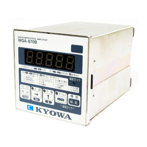
KYOWA WGA-670B-0 User manual

-~
ARTISAN
®
~I
TECHNOLOGY
GROUP
Your definitive source
for
quality
pre-owned
equipment.
Artisan Technology
Group
Full-service,
independent
repair
center
with
experienced
engineers
and
technicians
on staff.
We
buy
your
excess,
underutilized,
and
idle
equipment
along
with
credit
for
buybacks
and
trade-ins
.
Custom
engineering
so
your
equipment
works
exactly as
you
specify.
•
Critical
and
expedited
services
•
Leasing
/
Rentals/
Demos
• In
stock/
Ready-to-ship
•
!TAR-certified
secure
asset
solutions
Expert
team
ITrust
guarantee
I
100%
satisfaction
All
tr
ademarks,
br
a
nd
names, a
nd
br
a
nd
s a
pp
earing here
in
are
th
e property of
th
e
ir
r
es
pecti
ve
ow
ner
s.
Find the Kyowa WGA-670B-0 at our website: Click HERE

IM-A-529b October 2006
INSTRUMENTATION AMPLIFIER
WGA-670B
INSTRUCTION MANUAL
Thank you for purchasing KYOWA’s product WGA-670B
Instrumentation Amplifier.
Read this Instruction Manual carefully in order to make full use of
the high performance of the product.
Do not use the product in methods other than described in this
Manual.
Copyright © KYOWA ELECTRONIC INSTRUMENTS CO., LTD. All rights reserved.
This Instruction Manual may not be copied or reproduced, in whole or part, without consent of KYOWA.
This Instruction Manual has been prepared with great care. However, if the need should arise for more
information, contact KYOWA or our representative.
Contents of the Manual are subjected to change without notice.
The contents of the Instruction Manual are subjected to change without prior notice.


CONTENTS
SAFETY PRECAUTIONS ............................................................................................................................................ 1
PRIOR TO USE .............................................................................................................................................................................................1
SAFETY SYMBOLS.....................................................................................................................................................................................1
STANDARD ACCESSORIES....................................................................................................................................... 3
TYPES............................................................................................................................................................................... 3
1. PARTS NAMES & PRINCIPAL FUNCTIONS..................................................................................................... 4
1-1 FRONT PANEL .......................................................................................................................................................................................4
1-2 REAR PANEL .........................................................................................................................................................................................5
2. CONNECTION ........................................................................................................................................................... 6
2-1 INSTALLING TO PANEL ......................................................................................................................................................................6
2-2 WIRING...................................................................................................................................................................................................6
2-2-1 Terminal Board..................................................................................................................................................................................6
2-2-2 Connecting Power Supply.................................................................................................................................................................6
2-2-3 Connecting Transducer .....................................................................................................................................................................6
2-2-4 Connecting Control Input Terminal ..................................................................................................................................................7
2-2-5 Connecting High/Low Limit Comparator Output ............................................................................................................................7
2-2-6 Connecting Analog Output (D/A Output).........................................................................................................................................7
2-2-7 Connecting BCD Output (WGA-670B-1)........................................................................................................................................8
2-2-8 Connecting RS Output (WGA-670B-7) ...........................................................................................................................................8
2-2-9 Connecting TEDS Signal (WGA-670B-7) .......................................................................................................................................8
3. BASIC OPERATION FLOW ................................................................................................................................... 9
4. OPERATION & FUNCTION ................................................................................................................................. 10
4-1 KEY OPERATION ................................................................................................................................................................................10
4-1-1 Key Operation in Measuring Mode (Setting [LOCK])...................................................................................................................10
4-1-2 Key Operation in Function Selecting Mode ................................................................................................................................... 11
4-1-3 Key Operation in Function Setting Mode....................................................................................................................................... 11
4-2 FUNCTION ..........................................................................................................................................................................................12
4-2-1 Various Functions in Function Selecting Mode ..............................................................................................................................12
4-2-2 Digital ZERO Function...................................................................................................................................................................19
4-2-3 Setting High/Low Comparator & Hysteresis..................................................................................................................................20
4-2-4 Sensitivity Registering Calibration Function..................................................................................................................................21
4-2-5 Hold Function .................................................................................................................................................................................22
5. OPERATION TIMING............................................................................................................................................ 28
5-1 CONTROL INPUT (HOLD, RESET, ZERO).......................................................................................................................................28
5-2 HIGH/LOW LIMIT COMPARATOR OUTPUT ..................................................................................................................................29
5-3 DELAY TIME BETWEEN INPUT & OUTPUT SIGNALS................................................................................................................29

6. BCD OUTPUT OPTION ......................................................................................................................................... 30
6-1 OUTLINE ..............................................................................................................................................................................................30
6-2 PIN NO. & SIGNAL NAME.................................................................................................................................................................30
6-3 SETTING BCD OUTPUT.....................................................................................................................................................................31
6-4 CONNECTING BCD OUTPUT ...........................................................................................................................................................31
6-5 SIGNAL TIMING..................................................................................................................................................................................32
7. RS-232C OPTION..................................................................................................................................................... 33
7-1 OUTLINE ..............................................................................................................................................................................................33
7-2 RS-232C INTERFACE..........................................................................................................................................................................33
7-3 OUTLINE of CONTROL COMMAND ...............................................................................................................................................35
7-4 DETAILS of VARIOUS CONTROL COMMANDS............................................................................................................................37
8. TEDS OPTION.......................................................................................................................................................... 46
8-1 OUTLINE ..............................................................................................................................................................................................46
8-2 CONNECTION......................................................................................................................................................................................46
8-3 OPERATION .........................................................................................................................................................................................47
9. SPECIFICATIONS................................................................................................................................................... 49
9-1 SPECIFICATIONS ................................................................................................................................................................................49
9-2 OUTSIDE DRAWING ..........................................................................................................................................................................51
10. ERROR CODE LIST ............................................................................................................................................. 54

1
SAFETY PRECAUTIONS
WGA-670B Instrumentation Amplifier (hereinafter referred to as the WGA-670B) is designed to be used in the
following environment.
• Installation category (Over-voltage category): II (Refer to EN61010-1 Appendix J and IEC664)
• Pollution degree: 2 (Refer to EN61010-1 3.7.3)
PRIOR TO USE
This Instruction Manual describes details of WGA-670B Instrumentation Amplifier.
For safe use of the WGA-670B, do not forget to read the “Safety Precautions” prior to use.
KYOWA ELECTRONIC INSTRUMENTS CO., LTD. assumes no liability for any damages resulting from the
user’s failure to comply with the safety precautions.
SAFETY SYMBOLS
For safety operation of the WGA-670B, the following “WARNING” and “CAUTION” symbols are used in
“Safety Precautions” of this Instruction Manual.
WARNI NG
Improper operation of the system may result in severe injury or death of the
operator.
CAUTION
Improper operation of the system may result in injury to the operator and
physical damage to the system.
In addition, items in
CAUTION may lead to serious consequences. Take special attention to the
Safety Symbols.
The following symbols are use in the WGA-670B to call operator’s attention when operating the product.
Safety Symbols used in the WGA-670B.
WARNING
Indicates “Handling Precautions.” This symbol is attached to the WGA-670B
when it requires to refer to the Instruction Manual for securing safety of the
operator and the product.
CAUTION Indicates “Protective Ground Terminal.” Always connect to ground before
operating the product.

2
WARNING
1) If the potential secondary damage generates in the System due to deterioration of the WGA-670B, always
take appropriate technical measures for safety.
Or, defect in the system may occur resulting from erroneous output or malfunction of the instrument.
2) Mounting and wiring should be conducted more than 3 seconds after the power OFF.
Or, it may cause an electric shock to the operator or damage to the instrument.
3) Do not forget to put a cover on the terminal board.
Or, it may cause an electric shock to the operator.
4) Special care should be taken not to use the WGA-670B in environment with inflammable gas or vapor
Or, it may catch fire.
5) If the WGA-670B is faulty, emitting smoke or offensive odor or producing abnormal sound, immediately turn
OFF the power.
Or, it may cause fire and/or an electric shock to the operator.
Contact KYOWA’s representative for repair.
6) Do not put water or foreign matters into the WGA-670B. In case if any foreign matters are entered,
immediately turn OFF the power.
Or, it may cause fire and/or electric shock to the operator.
Contact KYOWA’s representative for repair.
7) Do not use a worn out power cable.
Or it may cause fire and/or electric shock to the operator.
8) Always operate the WGA-670B with the specified power voltage indicated in this Instruction Manual.
Or, it may cause fire and/or electric shock to the operator.
9) Do not operate the WGA-670B in environment with excessive moisture, dust or oil dust.
Or, it may cause fire and /or electric shock to the operator.
10)Do not disassemble the WGA-670B.
Or, it may cause deterioration or malfunction of the instrument.
11)When it started thundering, do not touch the WGA-670B or cable.
Or, it may cause an electric shock to the operator.
12)Always ground a protective ground terminal.
Or, it may cause an electric shock to the operator and/or damage to the WGA-670B.
CAUTION
1) Before wiring, confirm the rated power voltage and terminal assignment of the WGA-670B.
Then, conduct wirings in the correct manner.
2) Power consumption of the WGA-670B is maximum 20 VA. If it is unavoidably operated in environment
with poor power condition, it is recommended to use an insulated constant voltage transformer or the like.
3) Special care should be taken when the WGA-670B is used in environment with excessive vibration.
If it is operated at a location with excessive vibration or with continuous vibration, it may cause
measurement error and/or failure of the instrument.
Take great care not to drop the instrument during transportation and avoid applying strong impact.
Or, it may cause deterioration of the instrument.
4) Basically, the WGA-670B is designed to be used by connecting the strain gage transducer to the input
terminal. If it is used by connecting transducers other than above, contact KYOWA for information.
5) Operate the WGA-670B by conforming to the operating environment described in this Instruction Manual.
Or, it may cause malfunction and/or failure of the instrument.

3
STANDARD ACCESSORIES
The following accessories are enclosed with the WGA-670B. After unpacking, check all the items are correctly
prepared.
Unit label .....................................................................................................1
Warranty ......................................................................................................1
Instruction Manual ......................................................................................1
Note: A power supply cable is not enclosed with the WGA-670B. Customers are required to separately purchase
a power cable appropriate for the power supply in use.
(Ex. For 100 VAC: P-23, For 200 VAC: P-24)
TYPES
The WGA-670B has various types with optional functions as follows.
Model Name No option With BCD output With RS-232C output Compatible with TEDS
WGA-670B-0 ○
WGA-670B-1 ○
WGA-670B-7 ○○
TEDS: Transducer Electronic Data Sheet (hereinafter referred to as the TEDS)

4
1. PARTS NAMES & PRINCIPAL FUNCTIONS
1-1 FRONT PANEL
A) Indicator ...............................• Indicates measured values, selected functions, and set values.
• Normally, it indicates measured values responding to the output from the
transducer. However, if error occurs, the following appears.
OFL1: When measured value is exceeding the measuring range to the
minus side.
OFL2: When measured value is exceeding the measuring range to the
plus side.
OFL3: When the indicated value is below -19999.
OFL4: When the indicated value is above +19999.
B) Unit Label
C) [LOCK] LED .......................• When this LED is lit or flickering, no functions are set. Always turn OFF the
[LOCK] LED before setting functions.
D) [HIGH] Limit LED ..............• Lights up when the measured value exceeds the high limit value.
• Flickers when high limit value is indicated.
E) [LOW] Limit LED ...............• Lights up when the measured value is less than the low limit value.
• Flickers when low limit value is indicated.
F) Operation Key ......................• A pushbutton switch to operate the WGA-670B.
For operation, see “4 OPERATION & FUNCTIONS.”
E
D
AB
F
C

5
C
A
B
B
C
1-2 REAR PANEL
A) Optional ...............................• WGA-670B-0: None
• WGA-670B-1: Interface to output BCD coded WGA-670B indication.
• WGA-670B-7: Interface to connect the TEDS signal of the WGA-670B.
Also equipped with RS-232C interface.
Item A) in the above figure shows the WGA-670B-7.
B) Terminal Board ....................Nos.1 to 5: Transducer connection terminals.
1: Shield, 2: Bridge output (+), 3: Bridge exciter (-),
4: Bridge output (-), 5: Bridge exciter (+)
Nos. 6 to 9: Control contact input terminals.
6: COM, 7: RESET, 8: HOLD, 9: Digital ZERO input
Nos. 12 to 14: Analog output terminals.
12: Current output, 13: Common, 14: Voltage output
Nos. 15 to 17: Comparator open collector output terminals
15: COM, 16: LOW limit output, 17: HIGH limit output
No. 18: Protective ground terminal
Grounding should be made to prevent an electric shock
hazard.
Nos. 19 & 20: LINE IN. Connect AC power supply.
Nos. 10 & 11: Spare terminals. No connection
Nos. 21 & 22: TEDS signal connection terminals.
21: TEDS(+), 22: TEDS(COM)
C) Fitting Metal ........................• Fitting metal for fixing the WGA-670B to the panel.

6
2. CONNECTION
2-1 INSTALLING TO PANEL
To install the WGA-670B to a panel, prepare the panel according
to the specified panel cut dimensions as shown at the right.
Then, install theWGA-670B by referring to the following
instructions.
(1) Cut out the panel according to the panel cut dimensions.
(2) Remove screws of the fitting metals attached on both sides
of the WGA-670B and then, pull out the fitting metals.
(3) Set the WGA-670B into the cut out panel frame.
(4) Set the fitting metals on both sides of the WGA-670B.
(5) Tighten the screws and firmly fix the WGA-670B into the
panel.
2-2 WIRING
2-2-1 Terminal Board
• Remove the cover from the terminal board before conducting required wirings.
• It is recommended to attach press-fit terminals to the connecting wires.
Use press fit terminals (equivalent to JIS C 2805 conforming copper wiring press fit terminal 1.25-3).
• After completing wirings to the terminal board, do not forget to cover the terminal board.
2-2-2 Connecting Power Supply
• Power supply terminals are as follows.
No. 19: N, No. 20: L
• Always confirm the power voltage is 100 to 240V AC (±10%) and use a cable having higher withstand voltage
capacity than power voltage.
2-2-3 Connecting Transducer
• Connect a transducer to terminals from Nos. 1 to 5.
(Cable colors described below are KYOWA’s standard color codes)
No. 5: Bridge exciter plus (+) side (Red), No. 4: Bridge output minus (-) side (White)
No. 3: Bridge exciter minus (-) side (Black), No. 2: Bridge output plus (+) side (Green)
No. 1: Shielded wire
• For transducer wiring, use shortest possible 4-conductor shielded cable.
In addition, locate it apart from the power cable or other wirings that may generate noise.
• Bridge excitation voltage is set to 2 V prior to shipment. Since it can be selected to 10 V, set the voltage
appropriate for sensor specifications. (Selected with function selecting mode ‘F-13.’)
Panel cut dimensions
Plate thickness 1 to 5mm

7
Switch or
Open Collector
Input Connection Diagram
ExternalInternal
12V
1〜5mA →
Switch or
Open Collector
Input Connection Diagram
ExternalInternal
12V
1〜5mA →
Output Connection Diagram
COM
Max 30V
External
Internal
←Max 20mA
Output Connection Diagram
COM
Max 30V
External
Internal
←Max 20mA
2-2-4 Connecting Control Input Terminal
• Contact connection terminal is as follows.
No. 6: Common terminal (COMMON)
No. 7: Reset
No. 8: Hold
No. 9: ZERO
• For using the external switches; ZERO, HOLD, and RESET,
connect as shown in the right figure. (Open collector enabled)
• For connecting more than 1-m long cable, use a twisted cable.
• For connecting more than 3-m long cable, use a 2-conductor twisted
cable and always ground the shielded cable to the ground terminal.
(No. 18).
• In addition, for connecting more than 30-m long cable or using
outdoors, take special countermeasures against noise.
2-2-5 Connecting High/Low Limit Comparator Output
• Comparator output connection terminal is as follows.
No. 15: Common terminal (COMMON)
No. 16: Low limit
No. 17: High limit
• Connect as shown in the right figure.
• For connecting more than 1-m long cable, use a twisted cable.
• For connecting more than 3-m long cable, use a 2-conductor
twisted cable and do not forget to ground the shielded cable to
the ground terminal (No. 18).
• In addition, for connecting more than 30-m long cable or using
outdoors, take special countermeasures against noise.
2-2-6 Connecting Analog Output (D/A Output)
• Display value is output by converting into analog signal.
• Analog output terminals are as follows.
Rear terminal board No. 12: Current output (4 to 20mA)
No. 13: Common
No. 14: Voltage output (±10V)
• Use current output having load resistance 500 Ωor less and voltage output 2 kΩor more.
• For connecting more than 1-m long cable, use a twisted cable.
• For connecting more than 3-m long cable, use a 2-conductor twisted cable and do not forget to ground the
shielded cable to the ground terminal (No. 18).
• In addition, for connecting more than 30-m long cable or using outdoors, take special countermeasures against
noise.
COM

8
2-2-7 Connecting BCD Output (WGA-670B-1)
• See “6. BCD OUTPUT OPTION.”
2-2-8 Connecting RS Output (WGA-670B-7)
• See “7. RS-232C OPTION.”
2-2-9 Connecting TEDS Signal (WGA-670B-7)
• See “8. TEDS OPTION.”

9
3. BASIC OPERATION FLOW
Procedures for operating the WGA-670B are roughly described in the following.
For details, see “4. OPERATION & FUNCTIONS.”
Item Outline of Operation
(1) Power ON
Power ON and the WGA-670B is in measuring mode.
(See “4-1-1 Key Operation in Measuring Mode (Setting [LOCK])”
(2) Changing Mode
Press the FUNCTION key 2 seconds or more to activate the function selecting
mode.
(See 4-1-2 Key Operation in Function Selecting Mode)
(3) Calibration
Set the indication to function ‘F-02’ to conduct the actual load calibration or set it
to function ‘F-03’ to conduct sensitivity registering calibration.
(See “4-2-1 Various Functions in Function Selecting Mode.”)
(4) Changing Mode
Press the CANC key to activate the measuring mode.
(See “4-1-2 Key Operation in Function Selecting Mode.”)
(5) Setting High/Low
Limit
Press the HIGH key 2 seconds or more to activate the high limit setting mode and
then, set the high limit value.
In the same manner, press the LOW key 2 seconds or more to set the low limit
value.
(See “4-2-3 Setting High/Low Comparator & Hysteresis”)
(6) Adjusting
External Output
To activate the analog output (D/A output), set the analog output scale value with
the function ‘F-06.’
To activate the BCD output, set the BCD output logic with the function ‘F-11.’
(See “4-2-1 Various Functions in Function Selecting Mode.”
(7) Others
• To settle the unstable indication, use the function ‘F-07 Smoothing.’
• To add or subtract the constant, use the function ‘F-08 Additional.’
(See “4-2-1 Various Functions in Function Selecting Mode.”
• To set the indication to ZERO, press the ZERO key 2 seconds or more.
(See “4-2-2 Digital ZERO Function.”)
(Note) · If the [LOCK] LED is lit, no setting is allowed.
Before setting the required items, always confirm whether the [LOCK] LED on the front panel is turned
OFF.

10
4. OPERATION & FUNCTION
4-1 KEY OPERATION
4-1-1 Key Operation in Measuring Mode (Setting [LOCK])
• Power ON the WGA-670B and the measuring mode is activated in [LOCK] state.
• In the measuring mode, the WGA-670B measures load, pressure, torque, displacement and other physical
quantities by combining with a strain gage type transducer and indicates the measured values on the indicator.
• Various key operations in the measuring mode proceed to high limit setting mode, low limit setting mode,
function selecting mode, and to the [LOCK] state.
However, if it is in the [LOCK] state (with [LOCK] LED lit), key operations thereafter may be limited.
For details, see the following Table 4-1-1.
Table 4-1-1 Key Operation in Measuring Mode
Key Operation When [LOCK] LED is OFF When [LOCK] LED is ON
Press the ZERO key for 2 seconds.
Digital ZERO function activates
to set the indication to ZERO and
to return to the measuring mode.
No function is activated.
Press the HIGH key for 2 seconds.
High limit setting mode is
activated.
Press the LOW key for 2 seconds.
Low limit setting mode is
activated.
Only the set value is indicated.
Press the FUNCTION key for 2
seconds.
Function selecting mode is
activated.
No function is activated.
Press the HOLD key.
WGA-670B operates with preset
hold mode.
No function is activated.
Press the HOLD + FUNCTION keys
at the same time for 2 seconds.
[LOCK] LED lights up and the
WGA-670B returns to the
measuring mode.
[LOCK] LED lights out and
setting modes becomes available.

11
4-1-2 Key Operation in Function Selecting Mode
• Press the FUNCTION key for 2 seconds in the measuring mode to activate the function selecting mode. At
this time, function ‘F-01’ is indicated on the indicator.
• By pressing the →key or SHIFT + ←keys in the function selecting mode, various functions are selected
from ‘F-01’ to ‘F-14.’
Select the desired function and press the SET key. Then, the selected function is determined to activate the
function setting mode.
●There are the following 14 selective functions
F-01: Original value F-08: Additional Value
F-02: Actual Load Calibration F-09: Automatic ZERO Compensation
F-03: Sensitivity Registering Calibration F-10: Hysteresis
F-04: Hold Mode F-11: BCD Output Logic
F-05: Self Check F-12: Initialize
F-06: D/A Output Scale F-13: BV Select
F-07: Smoothing F-14: TEDS ON/OFF
●For details of functions, see “4-2-1 Various Functions in Function Selecting Mode.”
• Press the CANC key in the function selecting mode to return to the measuring mode.
4-1-3 Key Operation in Function Setting Mode
• Select the desired function in the function selecting mode and press the SET key to activate the selected
function setting mode.
• To set the required numerical value, change the current numerical value with the →, SHIFT + ←, ↑, and
SHIFT + ↓keys and press the SET key. Then, the set value is determined and stored in the memory at the
same time.
• When no numerical value is set, "…...."is indicated. Press the SET key in this state to activate the selected
function.
• Press the CANC key in the setting mode to return to the measuring mode.
●Numerical Value Setting Procedures
a) When setting the numerical value, setting available digit flickers.
b) Pressing the →key moves the flickering digit to the right. The flickering digit next to the right end moves
to the left end digit.
Pressing the SHIFT + ←keys moves the digit the other way round.
c) Pressing the ↑key changes the numerical value of the flickering digit as shown in the following.
Flickering digit in left end
→0 →1 →–1 →– →0 →
Other flickering digits
→0 →1 →2 →3 →4 →5 →6 →7 →8 →9
→0 →
Pressing the SHIFT + ↓keys moves the flickering digit the other way round.
d) Set decimal point in calibration functions ‘F-02 and F-03.’
A decimal point moves to the right by pressing the →key and moves to the left by pressing the SHIFT +
←keys.
Pressing the CANC key on the way returns to the previously set function selecting mode.

12
4-2 FUNCTION
4-2-1 Various Functions in Function Selecting Mode
• Function selecting mode has the following 14 functions.
F-01: Original value F-08: Additional Value
F-02: Actual Load Calibration F-09: Automatic ZERO Compensation
F-03: Sensitivity Registering Calibration F-10: Hysteresis
F-04: Hold Mode F-11: BCD Output Logic
F-05: Self Check F-12: Initialize
F-06: D/A Output Scale F-13: BV Select
F-07: Smoothing F-14: TEDS ON/OFF
• For details of each function, see the following Table 4-2-1.
Table 4-2-1 Various Functions in Function Selecting Mode
Function
Selecting Mode Function Name Key Operation & WGA-670B
Movement in Function Setting Mode
Functional
Description
F-01 Original Value ‘. . . . . ’ is indicated.
Press the SET key at this time and the
current input value is indicated in the unit
of mV/V.
•A function that
indicates the raw
output value of
the transducer.
F-02 Actual Load
Calibration
Conduct digital ZERO function with no
load applied to the transducer.
Then, apply load to the transducer.
Set a numerical value to be indicated at
this time and press the SET key.
Next, set a decimal point position and
press the SET key.
•Key code enable setting
‘00000’ is indicated.
Here, set the indication to read ‘00628’ or
‘11111’ and press the SET key. Then,
calibration value is updated.
The key code is enabled. Therefore, when
the calibration value is updated the next
time, the above operation is required. To
disable the key code, use the function
‘F-12.’
•Key code disable setting
‘00000’ is indicated.
Press the SET key as it is.
Then, the calibration value is updated.
The key code is disabled and the
calibration value is updated even if no
key code entered.
•A function that
applies the actual
load to the
transducer and sets
the indicated value
of that time.
●Before conducting
the actual load
calibration, do not
forget to conduct
digital ZERO
function.

13
Function
Selecting Mode Function Name Key operation & WGA-670B
Movement in Function Setting Mode
Functional
Description
F-02
Actual Load
Calibration
●The indication ‘00628’ or ‘11111’ is a
key code to prevent calibration value
from carelessly changing due to
malfunction.
F-03 Sensitivity
Registering
Calibration
Set transducer rated output (Unit: mV/V)
and press the SET key.
Next, set the required value to be
indicated and press the SET key.
Then, set a decimal point position and
press the SET key.
•Key code enable setting
‘00000’ is indicated.
Here, set the indication to read ‘00628’ or
‘11111’ and press the SET key. Then,
calibration value is updated.
The key code is enabled. Therefore, when
the calibration value is updated the next
time, the above operation is required. To
disable the key code, use the function
‘F-12.’
•Key code disable setting
‘00000’ is indicated. Press the SET key
as it is. Then, the calibration value is
updated.
The key code is disabled. The calibration
value is updated even if no key code is
entered.
●The indication ‘00628’ or ‘11111’ is a
key code to prevent calibration value
from carelessly changing due to
malfunction.
●Setting available range is ‘10000’ or
less per 0.1 mV/V.
•A function that
conducts calibra-
tion by registering
the rated output
and rated capacity
of the transducer
without applying
the actual load.
•Factory default is
‘4000’ when 2.000
mV/V is entered.
•For details, see
“4-2-4.”

14
Function
Selecting Mode Function Name Key Operation & WGA-670B
Movement in Function Setting Mode
Functional
Description
F-04 Hold Mode Indicates the following items (1), (2), and
(3).
(1) Setting Hold mode
0 : Tracking
1 : Arbitrary point hold
2 : Peak hold
3 : Block specified peak hold
4 : Time specified peak hold
(2) Display mode
0 : Normal display mode
1 : Hold display mode
(3) Comparison mode
0 : Normal comparison mode
1 : Hold comparison mode
Select and change numerics in items (1),
(2), and (3) and press the SET key.
Previously set delay time is indicated.
After it is changed, press the SET key.
Previously set specified time is indicated.
After it is changed, press the SET key.
●Delay time range
0.00 to 9.99 (sec)
●Specified time range
0.01 to 99.99 (sec)
•Sets various Hold
functions.
•For details, see
“4-2-5.”
For setting hold
display mode and
hold comparison
mode, hold modes 3
and 4 are enabled.
Set the delay time
and then, the hold
operation start can be
delayed by the preset
time.
F-05 Self-Check ‘. . . . . ’ is indicated.
Pressing the SET key at this time lights
up all the indicators to conduct checking.
The checked results are indicated as
shown in the right.
●If any faulty results appear on the
indicator, contact KYOWA or our
representatives.
•A function that
checks the stored
memory.
Good: Normal
E-01: RAM failure
E-02: Flash memory
failure
F-06 Analog Output
(D/A Output)
Scale
Set the indication to set the analog output
value to 0V or 4mA and press the SET
key.
Next, set the indication to set the analog
output value (D/A output) to 10 V or 20
mA and press the SET key. Then, analog
output is scaled.
●Setting range: ±19999
•A function that
defines and sets
ZERO and full
scale values.

15
Function
Selecting Mode Function Name Key Operation & WGA-670B
Movement in Function Setting Mode
Functional
Description
F-07 Smoothing Indicates the following items (1), (2), and
(3).
(1)Numberof (2)MinimumScale
Moving Averages
0:None 0:Displaysevery1scale.
1 : 8 times 1 : Displays every 2 scales.
2:16times 2:Displaysevery5scales.
3 : 32 times 3: Displays every 10 scales.
4 : 64 times 4 : Displays every 20 scales.
5 : 128 times 5 : Displays every 50 scales.
6 : 256 times 6 : Displays every 100 scales.
7 : 512 times 7 : Displays every 200 scales.
8 : 1024 times 8 : Displays every 500 scales.
9 : 2048 times 9 : Displays every 1000 scales.
(3) Analog filter
0: 100 Hz
1: 10 Hz
Select and change numerics in items (1), (2)
and (3) and press the SET key.
•A function that
stables the
indication by
smoothing
varying signals
issued from the
transducer.
•The smoothing
function is
classified into the
following 3
types.
Number of
moving averages:
The number of
times to average
the measured
value.
Minimum scale:
Minimum unit
that changes the
indicated value.
Analog filter:
Cuts the extra
high frequency
transferred
from the
transducer.
Factory default is
0: 100 Hz .
F-08 Additional Value Set the desired additional value and press
the SET key. The entered value is added to
the measured value and indicated.
●If digital ZERO function is activated
with the additional value set to the
measured value, the determined value is
indicated on the indicator.
●Setting range: ±19999
•A function that
adds the desired
numerical value
to the measured
value.
This manual suits for next models
3
Table of contents
Other KYOWA Amplifier manuals

KYOWA
KYOWA WGA-910A Series User manual

KYOWA
KYOWA DPM-900 Series User manual

KYOWA
KYOWA WGA-910A Series User manual

KYOWA
KYOWA WGA-670B User manual

KYOWA
KYOWA WGA-680A Series User manual

KYOWA
KYOWA WGI-400A User manual

KYOWA
KYOWA WGA-680A Series User manual

KYOWA
KYOWA WGA-680A Series User manual

KYOWA
KYOWA WGA-910A Series User manual

KYOWA
KYOWA WGA-120A User manual