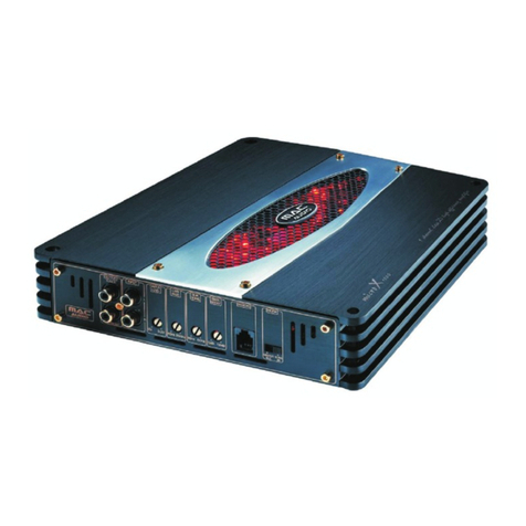
MAC Audio MPX 2000 Planning guide

MPX 2000
MPX 2500
2 KANAL LEISTUNGSVERSTÄRKER
2 CHANNEL POWER AMPLIFIER
AMPLIFICATEUR DE PUISSANCE À 2 CANAUX
BEDIENUNGSANLEITUNG/GARANTIEURKUNDE
OWNER’S MANUAL/WARRANTY DOCUMENT
MODE D’EMPLOI/CERTIFICAT DE GARANTIE

Bitte führen Sie das Gerät am Ende seiner Lebensdauer den zur
Verfügung stehenden Rückgabe- und Sammelsystemen zu.
At the end of the product’s useful life, please dispose of it at
appropriate collection points provided in your country.
Une fois le produit en fin de vie, veuillez le déposer dans un point
de recyclage approprié.

4
D
11
GB
17
F
24
NL
31
I
38
E
45
52
S
58
RUS
64
CHN
69
J
74
Abbildungen/Illustrations
P

D
4
D
Sehr geehrter MACAUDIO - Kunde,
mit dem Besitz des Car HiFi Leistungsverstärkers MPX 2000 / MPX 2500 können Sie
Ihre hohen Ansprüche an die Klangwiedergabe im Auto auf souveräne Weise erfüllen.
Der MPX 2000 / MPX 2500 eröffnet neue Qualitäten der Car HiFi-Wiedergabe imAuto;
sei es die beeindruckende Leistungsreserve für Tiefbässe, der niedrige Klirrfaktor oder
die neutrale Wiedergabe. Der Verstärker zeichnet sich durch einen niedrigen
Treiberstrom, schnelle Schaltfähigkeit und ausgezeichnete Temperaturstabilität aus.
Durch Zusammenschaltung von jeweils zwei Verstärkerkanälen zu einem Verstärker im
Brückenbetrieb kann eine verbesserte Dynamik in Verbindung mit einer höheren
Ausgangsleistungerreichtwerden.ErlebenSie,wiediesesHighTech-Gerätaufperfekte
Weise großartiges Klangempfinden vermitteln kann. Dazu wünschen wir Ihnen viel
Vergnügen.
Bitte lesen Sie die Einbauanleitung vollständig durch, bevor Sie den Verstärker
einbauen und in Betrieb nehmen.
1. TECHNISCHE DATEN MPX 2000
Stereo / Gebrückt
Max.Ausgangsleistung
(1 kHz Sinus Burst 2:8, B+=14,4V) 2 x 180 W / 1 x 500 W an 4 Ohm
Nennausgangsleistung (DIN 45 324, B+=14,4V) 2 x 60 W / 1 x 160 W an 4 Ohm
Max.Ausgangsleistung
(1 kHz Sinus Burst 2:8, B+=14,4V) 2 x 250 W an 2 Ohm
Nennausgangsleistung (DIN 45 324, B+=14,4V) 2 x 80 W an 2 Ohm
Lautsprecherimpedanz (Stereo) 2 – 8 Ohm
Frequenzgang 5 – 50 000 Hz (-3 dB)
Gesamtklirrfaktor (DIN 45 403) < 0,05 % (1 kHz)
Übersprechdämpfung (IEC 581 ) > 60 dB (1 kHz)
Geräuschspannungsabstand (IECA) > 100 dB
Eingangsempfindlichkeit LOW LEVEL INPUT 400 mV - 4V
Eingangsimpedanz LOW LEVEL INPUT 20 kOhm
Tiefpassfilter 40 – 300 Hz, 12 dB pro Oktave
Hochpassfilter 40 – 300 Hz, 12 dB pro Oktave
Bass Boost 0...12 dB bei 45 Hz
Versorgung + 12 V (9 – 15 V), Minus an Masse
Sicherung 1 x 20A
Abmessungen (B x H x T) 239 x 59 x 226 mm
Gewicht 1,9 kg
5
D
MPX 2500
Stereo / Gebrückt
Max.Ausgangsleistung
(1 kHz Sinus Burst 2:8, B+=14,4V) 2 x 225 W / 1 x 600 W an 4 Ohm
Nennausgangsleistung (DIN 45 324, B+=14,4V) 2 x 80 W / 1 x 240 W an 4 Ohm
Max.Ausgangsleistung
(1 kHz Sinus Burst 2:8, B+=14,4V) 2 x 300 W an 2 Ohm
Nennausgangsleistung (DIN 45 324, B+=14,4V) 2 x 120 W an 2 Ohm
Lautsprecherimpedanz (Stereo) 2 – 8 Ohm
Frequenzgang 5 – 50 000 Hz (-3 dB)
Gesamtklirrfaktor (DIN 45 403) < 0,05 % (1 kHz)
Übersprechdämpfung (IEC 581 ) > 60 dB (1 kHz)
Geräuschspannungsabstand (IECA) > 100 dB
Eingangsempfindlichkeit LOW LEVEL INPUT 400 mV - 4V
Eingangsimpedanz LOW LEVEL INPUT 20 kOhm
Tiefpassfilter 40 – 300 Hz, 12 dB pro Oktave
Hochpassfilter 40 – 300 Hz, 12 dB pro Oktave
Bass Boost 0...12 dB bei 45 Hz
Versorgung + 12 V (9 – 15 V), Minus an Masse
Sicherung 1 x 25A
Abmessungen (B x H x T) 239 x 59 x 226 mm
Gewicht 2,0 kg
TECHNISCHE ÄNDERUNGEN VORBEHALTEN
2. BESONDERHEITEN
•Komplementäre Gegentaktendstufe
•Automatische Ein-/Ausschaltung überAutoradio
•Stufenlos einstellbare Hoch- und Tiefpassfilter
•Stufenlos einstellbare Bassentzerrung
•Einstellbare Eingangsempfindlichkeit
•Brückbar 2-/1-Kanal-Betrieb
•Tri-Mode Betrieb
•Elektronische Schutzschaltung gegen Kurzschluss, Gleichspannungs-Offset und
Übertemperatur
•Mute-Schaltung zur Unterdrückung des Einschaltknacks
•Niederpegelausgänge (Cinch-Buchsen) zumAnschluss zusätzlicher Verstärker
•Betriebsanzeige (grüne LED) und Überlastungsanzeige (rote LED)

6
D
3. WICHTIGE HINWEISE VOR DEM EINBAU
•Dieses Gerät ist ausschließlich zumAnschluss an ein 12-Volt-System mit negativer
Masse geeignet.
•DiebeiderLeistungsabgabeabgestrahlteWärmeerforderteinenMontageplatzmit
ausreichender Luftzirkulation. Es ist sehr wichtig, dass die Kühlrippen des
Kühlkörpers nicht an einem Blech oder an einer Oberfläche anliegen, wodurch die
Luftirkulation eingeschränkt werden könnte. Der Verstärker darf nicht in kleine oder
unbelüftete Räume (z. B. Reserveradmulde oder unter dem Teppichboden des
Kraftfahrzeugs) eingebaut werden. Empfehlenswert ist eine Unterbringung im
Kofferraum.
•Montieren Sie den Verstärker so, dass er weitgehend vor Erschütterungen und
Staub und Schmutz geschützt ist.
•Achten Sie darauf, dass die Eingangs-/Ausgangskabel weit genug von den
Stromversorgungskabeln entferntsind, da es sonst zu Störeinstrahlungenkommen
kann.
•· Achten Sie darauf, dass die Sicherung und die Bedienungselemente nach der
Montage zugänglich sind.
•Die Leistung und Zuverlässigkeit der Anlage ist von der Qualität des Einbaus
abhängig. Lassen Sie die Montage vorzugsweise von einem Fachmann
vornehmen, speziell dann, wenn es sich um eine Installation mit mehreren
Lautsprechern oder um ein komplexes Mehrwege-System handelt.
4. ANSCHLÜSSE
4.1 STROMVERSORGUNG UND EINSCHALTAUTOMATIK
Wichtiger Hinweis: Bevor Sie mit der Installation beginnen, trennen Sie die
Plusklemme der Autobatterie ab, um Kurzschlüsse zu
vermeiden.
Die in Auto-Bordnetzen übliche Stromverkabelung ist nicht ausreichend für den Bedarf
einesLeistungsverstärkers.AchtenSiedarauf,dassdieStromleitungen zurGND undzur
+12 V Klemme ausreichend dimensioniert sind. Für die Verbindung von der Batterie zu
den Stromklemmen des Verstärkers ist ein Kabelquerschnitt von mindestens 6 mm²
(MPX 2000) bzw. 10 mm² (MPX 2500) zu verwenden.
ZuerststellenSiedieVerbindungzwischenderGND-KlemmedesVerstärkerssowie dem
Minuspol der Batterie her. Es ist sehr wichtig, eine gute Verbindung herzustellen.
Schmutzrestesind sorgfältigvomAnschlusspunktderBatteriezu entfernen.Ein lockerer
Anschluss kann eine Fehlfunktion oder Störgeräusche und Verzerrungen zur Folge
haben.

7
D
DerVerstärkeranschluss+12VwirdnunmiteinemStromkabelmitintegrierterSicherung
mit dem Pluspol der Batterie verbunden. Die Sicherung sollte sich in Nähe der Batterie
befinden, die Kabellänge vom Pluspol der Batterie bis zur Sicherung muss aus
Sicherheitsgründen unter 60 cm liegen. Die Sicherung setzen Sie erst nach Abschluss
aller Installationsarbeiten einschließlich der Lautsprecheranschlüsse ein.
Schließen Sie nun die Fernsteuerleitung des Car HiFi-Receivers an die Steuerbuchse
REM des Verstärkers an. Für die Verbindung zwischen dem REMOTE-Anschluss des
Verstärkers und dem Steuergerät ist ein Kabel mit einem Querschnitt von 0,75 mm²
ausreichend.
4.2 AUDIOKABEL
Bei der Installation desAudiokabels zwischen dem Cinch-Ausgang desAutoradios und
dem Cinch-Eingang des Verstärkers im Fahrzeug ist darauf zu achten, dass dasAudio-
und das Stromversorgungskabel möglichst nicht auf derselben Seite des Fahrzeugs
verlegt werden. Besser ist eine räumlich getrennte Installation, d.h. eine Installation des
Stromkabels imlinkenKabelschachtund desAudiokabelsimrechten Kabelschacht oder
umgekehrt.DamitwirddasÜbersprechenvonStörungenaufdasAudio-Signalverringert.
4.3 LAUTSPRECHERANSCHLÜSSE
•Im normalen Betriebsmodus (das heißt jeweils ein Lautsprecher an jedem
einzelnen Verstärkerkanal) ist der kleinsteAbschlusswiderstand 2 Ohm pro Kanal.
•Im Brückenbetrieb (jeweils zwei Verstärkerausgänge zusammengeschaltet)
verdoppelt sich der kleinsteAbschlusswiderstand auf 4 Ohm.
•Im Tri-Mode darf die Impedanz nicht unter 2 Ohm pro Kanal liegen.
•Schließen sie die Lautsprecher Minusklemmen niemals am Fahrzeugchassis an.
•Niemals die +12 V Versorgungsspannung mit einem Lautsprecherausgang
verbinden. Dieses führt zur Zerstörung der Verstärkerendstufe.
Wird der Verstärker mit niedrigeren Abschlusswerten betrieben oder falsch
betrieben wie oben genannt, kann dieses dazu führen, dass sowohl der Verstärker
selbst als auch die Lautsprecher beschädigt werden. In diesem Fall erlischt die
Garantie.

8
D
5. BEDIENUNGSELEMENTE UND EIN-/AUSGÄNGE
5.1 EINSTELLUNG DER EINGANGSEMPFINDLICHKEIT
Die Eingangsempfindlichkeit kann an jedes Autoradio oder Kassettendeck angepasst
werden.DrehenSie denLautstärkereglerIhresRadiosaufMittenstellung undstellenSie
dann den Eingangspegelregler (3) so ein, dass sich eine mittlere, durchschnittliche
Lautstärke ergibt. Bei dieser Einstellung sind normalerweise genügend
Leistungsreserven bei optimalem Geräuschspannungsabstand gewährleistet.
ACHTUNG: Laute Testsignale nur kurz wiedergeben, um Beschädigungen der
Lautsprecher zu vermeiden.
5.2 TIEFPASSFILTER MIT REGELBARER ÜBERGANGSFREQUENZ
Wird der Verstärker als Subwooferverstärker benutzt, stellen Sie den Schalter (7) auf
„LPF“. Stellen Sie am Regler (6) die gewünschte Übergangsfrequenz ein. Damit ist das
Filter den klanglichen Erfordernissen des verwendeten Tieftöners anpassbar.
DiehoheFlankensteilheitdesFilterssorgtfüreinepräziseAbsenkungmittlererundhoher
Frequenzbereiche.
5.3 HOCHPASSFILTER MIT REGELBARER ÜBERGANGSFREQUENZ
Soll der Verstärker als Verstärker für Satellitenlautsprecher (Mittel-/ Hochton-
Lautsprecher) verwendet werden, stellen Sie den Schalter (7) auf „HPF“. Stellen Sie am
Regler (5) die gewünschte Übergangsfrequenz ein. Somit werden nur Frequenzen
oberhalb der eingestellten Übergangsfrequenz verstärkt. Damit können Verzerrungen
durchzugroßenMembranhubbeitiefenFrequenzenundkleinenSatellitenlautsprechern
wirkungsvoll minimiert werden, ohne den Tieftonpegel zu reduzieren.
5.4 BASS-BOOST
Mit Hilfe der Bass-Boost Funktion (4) wird eine Anhebung oder eine Entzerrung der
unteren Bassfrequenzen erreicht.
5.5 AUSGÄNGE ZUM ANSCHLUSS WEITERER VERSTÄRKER
Das Eingangssignal der LINE INPUT Anschlüsse L und R (2) wird direkt an die
Ausgangsbuchsen LINE OUT (1) L und R weitergeleitet. Die LINE OUT Anschlüsse
ermöglichen denAnschluss weiterer Verstärker ohne zusätzliche T-Stecker und Kabel.

9
D
BILD 1 STROMVERSORGUNG- UND FERNEINSCHALTUNGSANSCHLUSS
(1) Anschlussklemme GND für die Masse, zum Minuspol der Batterie
(2) Anschlussklemme REM für die Ferneinschaltung
(3) Anschlussklemme für + 12 V Batteriespannung
(4) Batterie
(5) Kabelsicherung
(6) ZumAutomatikantennenanschluss IhresAutoradios
Wenn Ihr Autoradio nicht mit einem Automatikantennenanschluss ausgestattet ist,
ist dieses Kabel mit dem Pluspol (+) am Zündschloss zu verbinden. In diesem Fall
sollte ein Ein-/Ausschalter zwischengeschaltet werden. Achten Sie darauf, dass
dieser Schalter ausgeschaltet wird, wenn der Verstärker nicht benutzt wird.
BILD 2 STEREO- BETRIEB
SollderVerstärkervoneinemAutoradiomit 2Ausgangskanälenangesteuertwerdenund
2 Lautsprecher betreiben, dann sind die Anschlüsse und Einstellungen wie in Bild 2
vorzunehmen.BeiVerwendungdesVerstärkersfürSatellitenlautsprecherwirdzusätzlich
das Hochpassfilter eingeschaltet, siehe dazu Kapitel 5.3
(1) ZumAutoradio,Ausgang links
(2) ZumAutoradio,Ausgang rechts
(3) Lautsprecher links
(4) Lautsprecher rechts
BILD 3 BRÜCKENBETRIEB MIT STEREO-AUTORADIO
Soll der Verstärker eine höhere Leistung erzielen zum Betrieb eines Subwoofers, dann
sind die Anschlüsse und Einstellungen wie in Bild 3 vorzunehmen. Der Einsatz des
verwendeten Tiefpassfilters wird in Kapitel 5.2 beschrieben.
(1) ZumAutoradio,Ausgang links
(2) ZumAutoradio,Ausgang rechts
(3) Subwoofer
BILD 4 MONO-BETRIEB MIT EINEM AUTORADIO MIT SUBWOOFERAUSGANG
(1) Zum Autoradio, Subwooferausgang
(2) Subwoofer

10
D
BILD 5 BEDIENUNGSELEMENTE UND EIN-/AUSGÄNGE
(1) Ausgänge zumAnschließen weiterer Verstärker
(2) Niederpegeleingang
(3) Eingangspegelregler
(4) Bass-Boost-Regler
(5) Übergangsfrequenzregler für den Hochpass
(6) Übergangsfrequenzregler für den Tiefpass
(7) Wahlschalter FULL/ LPF (Tiefpass) / HPF (Hochpass)
(8) MONO/STEREO-Schalter

11
GB
Dear MAC AUDIO Customer,
The MPX 2000 / MPX 2500 car hi-fi power amplifier will enable you to satisfy your high
demands on sound reproduction in your car. With its impressive deep-bass power
reserves,low harmoniccontentandneutralreproduction, theMP2000 /MPX2500takes
car hi-fi to new heights. The amplifier is characterized by low operating current, rapid
switchingcapabilitiesand excellent temperature stability. Increased output power can be
achieved by switching two amplifier channels in an amplifier together in bridging mode.
Experience and enjoy how this high-tech machine perfectly reproduces magnificent
sound.
Please read all of the owner's manual before installing and using the amplifier.
1. TECHNICAL DATA MPX 2000
Stereo / Bridged
Max. output power
(1 kHz sinus burst 2:8, B+=14.4V) 2 x 180 W / 1 x 500 W on 4 Ohm
Nominal output power
(DIN 45 324, B+=14.4V) 2 x 60 W / 1 x 160 W on 4 Ohm
Max. output power
(1 kHz sinus burst 2:8, B+=14.4V) 2 x 250 W on 2 Ohm
Nominal output power
(DIN 45 324, B+=14.4V) 2 x 80 W on 2 Ohm
Loudspeaker impedance (stereo) 2 – 8 Ohm
Frequency response 5 – 50 000 Hz (-3 dB)
Total harmonic content (DIN 45 403) < 0.05% (1 kHz)
Stereo separation (IEC 581 ) > 60 dB (1 kHz)
Weighted noise distance (IECA) > 100 dB
Input sensitivity LOW LEVEL INPUT 400 mV – 4 V
Input impedance LOW LEVEL INPUT 20 kOhm
Low-pass filter 40 – 300 Hz, 12 dB per octave
High-pass filter 40 – 300 Hz, 12 dB per octave
Bass boost 0…12 dB at 45 Hz
Supply +12 V (9 – 15 V), minus to ground
Fuse 1 x 20A
Sizes (W x H x D) 239 x 59 x 226 mm
Weight 1.9 kg

12
GB
MPX 2500
Stereo / Bridged
Max. output power
(1 kHz sinus burst 2:8, B+=14.4V) 2 x 225 W / 1 x 600 W on 4 Ohm
Nominal output power
(DIN 45 324, B+=14.4V) 2 x 80 W / 1 x 240 W on 4 Ohm
Max. output power
(1 kHz sinus burst 2:8, B+=14.4V) 2 x 300 W on 2 Ohm
Nominal output power
(DIN 45 324, B+=14.4V) 2 x 120 W on 2 Ohm
Loudspeaker impedance (stereo) 2 – 8 Ohm
Frequency response 5 – 50 000 Hz (-3 dB)
Total harmonic content (DIN 45 403) < 0.05% (1 kHz)
Stereo separation (IEC 581 ) > 60 dB (1 kHz)
Weighted noise distance (IECA) > 100 dB
Input sensitivity LOW LEVEL INPUT 400 mV – 4 V
Input impedance LOW LEVEL INPUT 20 kOhm
Low-pass filter 40 – 300 Hz, 12 dB per octave
High-pass filter 40 – 300 Hz, 12 dB per octave
Bass boost 0…12 dB at 45 Hz
Supply +12 V (9 – 15 V), minus to ground
Fuse 1 x 25A
Sizes (W x H x D) 239 x 59 x 226 mm
Weight 2 kg
SUBJECT TO TECHNICAL CHANGE
2. FEATURES
•Complementary push-pull final stage
•Automatic switching on/off via car radio
•Infinitely adjustable high pass and low pass filters
•Infinitely variable bass equalisation
•Adjustable input sensitivity
•Bridgeable 2-/1-channel mode
•Tri-mode
•Electronic protective circuit against short circuiting, DC offset and excess
temperature
•Mute switch for suppressing switch-on crackle interference
•Low-level outputs (cinch jacks) for connecting additional amplifiers
•Operating display (green LED) and overload indicator (red LED)

13
GB
3. IMPORTANT INSTALLATION INFORMATION
•This appliance may only be connected to a 12 volt system with negative ground.
•The heat radiated when the amplifier is used means that sufficient air circulation is
required at the place of installation. It is very important that the cooler's cooler ribs
do not contact any metal plating or any surfaces which could impair air circulation.
The amplifier may not be installed in small confined spaces or spaces without air
circulation (e.g. spare wheel recess or under the vehicle carpeting). Installation in
the boot is recommended.
•Install the amplifier in such a way that it is protected as far as possible against
vibrations and dust and dirt.
•Makesurethat the input/output cablesaresufficientlydistantfromthepower supply
cables as otherwise interference may occur.
•Make sure that the fuse and operating elements are accessible after installation.
•The appliance's reliability and performance depend on the quality of installation.
Preferablygetanexperttoinstallthesystem,particularlyifyouwanttoinstallseveral
loudspeakers or a complex multi-way system.
4. CONNECTIONS
4.1 POWER SUPPLY AND AUTOMATIC SWITCHING ON
Important notice: Before commencing the installation, disconnect the plus
terminals from the car battery in order to prevent short
circuits.
The power cabling usually installed in on-board car networks is not sufficient for a power
amplifier's demands. Make sure that the power lines to GND and to the +12 V terminal
have been sufficiently specified. A cable cross-section of at least 6 mm² (MPX 2000) /
10 mm² (MPX 2500) must be used to connect the battery to the amplifier's terminals.
First connect the amplifier's GND terminal to the battery's minus pole. It is very important
that the connection is good. Dirt residues must be carefully removed from the battery's
connection point. A loose connection may cause malfunctions or interference noise or
distortion.
The +12 V amplifier connection must then be connected with a power cable possessing
anintegratedfusetothebattery'spluspole.Thefusemustbelocatedclosetothebattery,
the length of cable from the battery's positive pole to the fuse must be less than
60centimetresforsafetyreasons.Onlyinsertthefusewhenallinstallationwork,including
the connection of the loudspeakers, has been completed.
Now connect the car hi-fi receiver's remote control connection to the amplifier's REM
control jack. A cable with a cross-section of 0.75 mm² is sufficient for connecting the
amplifier's REMOTE connection and the control device.

14
GB
4.2 AUDIO CABLES
When installing the audio cable between the cinch output of your car receiver and the
cinch input of the amplifier inside your car, the audio and power supply cables should,
wherever possible, not be routed along the same side of the vehicle. We recommend an
isolated installation, e.g. routing the power cable through the cable duct on the left-hand
sideand the audio cable through the cableducton the right-hand side or vice versa. This
reduces interference due to crosstalk into the audio cables.
4.3 LOUDSPEAKER CONNECTIONS
•In normal operating mode (i.e. one loudspeaker on each individual amplifier
channel), the lowest terminal resistance is 2 ohm per channel.
•In bridging mode (two amplifier outputs combined) the lowest terminal resistance
doubles to 4 ohm.
•The impedance in tri-mode may not fall below 2 ohm per channel.
•Never connect the loudspeakers' minus terminals to the vehicle chassis.
•Never connect the +12 V supply voltage to a loudspeaker output as this would
destroy the amplifier final stage.
If the amplifier is operated with lower terminal resistances or incorrectly used as
described above, both the amplifier and the loudspeakers may be damaged. The
warranty becomes void in such cases.
5. OPERATING ELEMENTS AND IN/OUTPUTS
5.1 SETTING THE INPUT SENSITIVITY
The input sensitivity may be adapted to any car radio or tape deck. Turn the volume
control of your radio to its central position and then adjust the input-level control (3) to
produce an average medium volume. This setting usually provides sufficient power
reserves at optimum weighted noise voltage.
ATTENTION: only reproduce loud test noises briefly to prevent damaging the
loudspeakers.
5.2 LOW-PASS FILTER WITH ADJUSTABLE CROSS-OVER FREQUENCY
Iftheamplifierisusedasasubwooferamplifier,settheswitch(7)to"LPF”.Setthedesired
cross-over frequency with the control (6). This makes the filter adaptable to the installed
woofer's sound requirements.
Thefilter's high edge steepness is responsible for the precision reduction of mediumand
high frequency ranges.

15
GB
5.3 HIGH-PASS FILTER WITH ADJUSTABLE CROSS-OVER FREQUENCY
If the amplifier is to be used as an amplifier for satellite loudspeakers (mid-range/tweeter
loudspeakers), set switch (7) to "HPF". Set the desired cross-over frequency with the
control (5). Only the frequencies above the set cross-over frequency will then be
amplified. This effectively minimizes distortions caused by excessive membrane
movementatlowfrequencies and small satellite loudspeakerswithoutreducingthebass
level.
5.4 BASS-BOOST
The bass-boost function (4) is used to increase or equalize the lower bass frequencies.
5.5 OUTPUTS FOR CONNECTING ADDITIONAL AMPLIFIERS
The input signal of the LINE INPUT connections L and R (2) is forwarded directly to the
LINE OUT (1) L and R jacks. The LINE OUT connections allow the use of additional
amplifiers without requiring additional T-plugs and cables.
FIG. 1 POWER SUPPLY / REMOTE SWITCH-ON CONNECTION
(1) GND terminal for the ground, to the battery's minus pole
(2) REM terminal for remote switch-on
(3) Terminal for +12 V battery voltage
(4) Battery
(5) Cable fuse
(6) To your car radio's automatic aerial connection
If your car is not equipped with an automatic aerial connection, connect this cable's
plus pole (+) to the ignition lock. An on/off switch should be inserted in this case.
Make sure that this switch is switched off if the amplifier is not used.
FIG. 2 STEREO MODE
Connect and set the amplifier as shown in Fig. 2 if it is to be controlled with two output
channels and to use two loudspeakers. The high-pass filter must also be activated if the
amplifier is also used for satellite loudspeakers. See Chapter 5.3.
(1) To the car radio, left output
(2) To the car radio, right output
(3) Loudspeaker left
(4) Loudspeaker right

16
GB
FIG. 3 BRIDGE MODE WITH STEREO CAR RADIO
If the amplifier has to generate more power to operate a subwoofer, connect and set it
as shown in Fig. 3. The use of the low-pass filter is described in Chapter 5.2.
(1) To the car radio, left output
(2) To the car radio, right output
(3) Subwoofer
FIG. 4 MONO MODE WITH ONE CAR RADIO WITH SUBWOOFER OUTPUT
(1) To the car radio, subwoofer output
(2) Subwoofer
FIG. 5 OPERATING ELEMENTS AND IN/OUTPUTS
(1) Outputs for connecting additional amplifiers
(2) Low-level input
(3) Input level control
(4) Bass-booster control
(5) Cross-over frequency control for the high pass
(6) Cross-over frequency control for the low pass
(7) (FULL) / LPF (low pass filter) / HPF (high pass filter) option switch
(8) Mono-stereo switch

17
F
Très cher client de MACAUDIO
Avec l’acquisition de l’amplificateur de puissance MPX 2000 / MPX 2500 du Car Hi-Fi,
vous pouvez satisfaire à la perfection vos hautes exigences pour la restitution sonore
dansvotrevoiture.LeMPX2000/MPX2500offredenouvellesqualitéspourlarestitution
sonore du Car Hi-Fi dans votre voiture; que ce soit pour les impressionnantes réserves
de performances pour les basses graves, le faible facteur de vibrations ou la restitution
neutre. L’amplificateur se distingue par ses faibles manipulations électriques, ses
capacités de branchements et sa remarquable stabilité de température. Une dynamique
amélioréeenrelationavecunepuissancedesortiepeutêtreatteinteparunbranchement
conjugué de chacun des deux canaux d’amplificateur à un amplificateur en
fonctionnement pontable.Appréciez vous même la perfection sonore de cet appareil de
haute technologie. Pour cela, nous vous souhaitons beaucoup de plaisir.
Veuillez s’il vous plaitlire attentivementtoutes les instructions d’installationavant
que vous installiez l’amplificateur et le fassiez fonctionner.
1. CARACTERISTIQUES TECHNIQUES MPX 2000
Stéréo / ponté
Puissance de sortie maximale
(1 kHz Sinus Burst 2:8, B+=14,4V) 2 x 180 W / 1 x 500 W à 4 Ohm
Puissance RMS (DIN 45 324, B+=14,4V) 2 x 60 W / 1 x 160 W à 4 Ohm
Puissance de sortie maximale
(1 kHz Sinus Burst 2:8, B+=14,4V) 2 x 250 W à 2 Ohm
Puissance RMS (DIN 45 324, B+=14,4V) 2 x 80 W à 2 Ohm
Impédance haut-parleur
(fonctionnement stéréo) 2 – 8 Ohm
Zone de fréquence 5 – 50 000 Hz (-3 dB)
Taux de distorsion total (DIN 45 403) < 0,05% (1 kHz)
Affaiblissement diaphonique des canaux
(IEC 581) > 60 dB (1 kHz)
Ecart signal / bruit (IECA) > 100 dB
Sensibilité d’entrée LOW LEVEL INPUT 400 mV – 4 V
Impédance d’entrée LOW LEVEL INPUT 20 kOhm
Filtre passe-bas 40 – 300 Hz, 12 dB par octave
Filtre passe-haut 40 – 300 Hz, 12 dB par octave
Bass Boost 0…12 dB à 45 Hz
Alimentation + 12 V (9 – 15 V), négatif à la masse
Fusible 1 x 20A
Dimensions (L x H x P)) 239 x 59 x 226 mm
Poids 1,9 kg

18
F
MPX 2500
Stéréo / ponté
Puissance de sortie maximale
(1 kHz Sinus Burst 2:8, B+=14,4V) 2 x 225 W / 1 x 600 W à 4 Ohm
Puissance RMS (DIN 45 324, B+=14,4V) 2 x 80 W / 1 x 240 W à 4 Ohm
Puissance de sortie maximale
(1 kHz Sinus Burst 2:8, B+=14,4V) 2 x 300 W à 2 Ohm
Puissance RMS (DIN 45 324, B+=14,4V) 2 x 120 W à 2 Ohm
Impédance haut-parleur
(fonctionnement stéréo) 2 – 8 Ohm
Zone de fréquence 5 – 50 000 Hz (-3 dB)
Taux de distorsion total (DIN 45 403) < 0,05% (1 kHz)
Affaiblissement diaphonique des canaux
(IEC 581) > 60 dB (1 kHz)
Ecart signal / bruit (IECA) > 100 dB
Sensibilité d’entrée LOW LEVEL INPUT 400 mV – 4 V
Impédance d’entrée LOW LEVEL INPUT 20 kOhm
Filtre passe-bas 40 – 300 Hz, 12 dB par octave
Filtre passe-haut 40 – 300 Hz, 12 dB par octave
Bass Boost 0…12 dB à 45 Hz
Alimentation + 12 V (9 – 15 V), négatif à la masse
Fusible 1 x 25A
Dimensions (L x H x P)) 239 x 59 x 226 mm
Poids 2 kg
SOUS TOUTES RESERVES DE MODIFICATIONS TECHNIQUES
2. PARTICULARITES
•Stages finaux complémentaires de cadences opposées
•Mise en marche et arrêt automatiques par l’autoradio
•Filtre passe-haut / passe-bas réglable en continu
•Equilibrage de basse réglable en continu
•Sensibilité d’entrée réglable
•Fonctionnement à 2/1 canaux pontables
•Fonctionnement en Tri mode
•Circuitélectroniqueprotégécontrelescourts-circuits,lesoffsetsde tensioncontinue
et les surcharges thermiques
•Branchement Mute pour la suppression du craquement d’allumage
•Sorties à bas niveaux (bornes Cinch) pour le branchement d’amplificateurs
supplémentaires
•Indicateur de service (DEL verte) et indicateur de surcharge (DEL rouge)

19
F
3. RECOMMANDATIONS IMPORTANTES AVANT L’INSTALLATION
•Cet appareil convient exclusivement au branchement à un système de 12 volts à
masse négative.
•La chaleur provenant de l’utilisation nécessite un espace de montage avec une
circulation de l’air suffisante. Il est important que les canaux de refroidissement de
l’appareilde refroidissement nesoientpasen contactavec une tôle ou une surface,
qui pourraient causer une réduction de la circulation de l’air. L’amplificateur ne peut
pas être installé dans un petit espace non aéré (par exemple la place utilisée pour
la roue de secours ou sous le tapis de sol de la voiture). Une installation dans le
coffre est hautement recommandée.
•Montez l’amplificateur de manière à ce qu’il soit protégé au maximum contre les
secousses et vibrations ainsi que contre la poussière et les saletés.
•Veillez à ce que les câbles de sortie et d’entrée soient assez éloignés du câble
d’alimentation électrique, afin d’éviter tout son parasite.
•Veillezàcequelefusibleetlesélémentsd’utilisationdel’appareilsoientaccessibles
après le montage.
•La puissance et fiabilité de l’appareil dépendent de la qualité de l’installation. Il est
préférable de confier le montage à un spécialiste, surtout lorsqu’il s’agit d’une
installation comprenant plusieurs haut-parleurs ou d’un système complexe à
plusieurs voies.
4. BRANCHEMENTS
4.1 ALIMENTATION ELECTRIQUE ET ALLUMAGE AUTOMATIQUE
Recommandation importante: Avant quevous necommenciez avecl’installation,
séparezla bornepositive dela batterieafin d’éviter
tout risque de court-circuit.
Le câblage électrique habituel n’est pas suffisant pour les besoins d’un amplificateur de
puissance. Veillez à ce que les câbles électriques soient proprement dimensionnés au
GND et aux bornes +12 V. Pour le raccordement de la batterie aux bornes électriques
del’amplificateur, un câble d’au moins 6 mm² (MPX2000)/10 mm² (MPX 2500) doit être
utilisé.
Raccordez d’abord la borne GND de l’amplificateur avec le pôle négatif de la batterie. Il
est très important que le raccordement soit fait de manière parfaite. Les reliquats de
saletés doivent être enlevés avec soin du point de branchement de la batterie. Un
raccordement trop lâche peut être la cause d’une fonction défaillante ou de bruits
brouillés ou de déformations.
Lebranchementde l’amplificateur de+12V doit maintenantêtreraccordéavec un câble
électrique avec un fusible intégré à pôle positif. Le fusible doit être positionné près de la
batterie, la longueur du câble allant du pole positif de la batterie au fusible doit être, pour

20
F
desraisonsdesécurité,inférieureà60cm.Vousdevezplacerlefusibleseulementaprès
avoirterminé touslestravaux d’installation,ycomprisle branchementdeshaut-parleurs.
Vous devez maintenant connecter le câble de commandement à distance du récepteur
Car Hi-Fi à la borne de commande REM de l’amplificateur. Pour la connexion entre le
branchement REMOTE de l’amplificateur à l’appareil de commande, un câble de
0,75 mm² de section est suffisant.
4.2 CABLES AUDIO
Lors de l'installation du câble audio entre la sortie cinch de votre autoradio et l'entrée
cinch de l'amplificateur à l'intérieur de votre voiture, aussi souvent que cela est possible,
les câbles audio et alimentation ne doivent pas cheminer sur le même côté du véhicule.
Nous recommandons une installation isolée, par exemple le cheminement du câble
d'alimentation dans le passage de câbles du côté gauche et celui du câble audio dans
le passage de câbles du côté droit ou vice versa. Ceci réduit la diaphonie introduite dans
les câbles audio.
4.3 BRANCHEMENTS DES HAUT-PARLEURS
•Dans un mode de fonctionnement normal (c’est à dire un haut-parleur pour chaque
canal d’amplificateur) la résistance de branchement la plus basse est de 2 Ohm
par canal.
•Dans le fonctionnement pontable (chacune des deux sorties de l’amplificateur sont
branchées ensembles) la résistance de branchement la plus basse est multipliée
par deux et atteint 4 Ohm.
•Dans le Tri mode, l’impédance ne peut pas être de moins de 2 Ohm par canal.
•Ne raccordez jamais les bornes négatives des haut-parleurs au châssis de la
voiture.
•Ne connectez jamais la tension électrique de +12 V à la sortie du haut-parleur. Ceci
pourrait endommager le stage final de l’amplificateur.
Si l’amplificateur est mis en marche avec des valeurs de branchements trop
basses ou est mis en marche d’une façon incorrecte comme décrit ci-dessus, ceci
peut endommager aussi bien l’amplificateur que les haut-parleurs eux-mêmes.
Dans ce cas, la garantie n’est plus valable.
This manual suits for next models
3
Table of contents
Languages:
Other MAC Audio Amplifier manuals

MAC Audio
MAC Audio MPX 4500 User manual

MAC Audio
MAC Audio FEARLESS 5000 D User manual

MAC Audio
MAC Audio FEARLESS 1000 D Planning guide

MAC Audio
MAC Audio Micro X 1000 Planning guide

MAC Audio
MAC Audio FEARLESS 4000 D User manual

MAC Audio
MAC Audio MP MONO Planning guide

MAC Audio
MAC Audio FEARLESS 2200 D Planning guide

MAC Audio
MAC Audio Z 4200 Planning guide

MAC Audio
MAC Audio APM 4.0 Planning guide