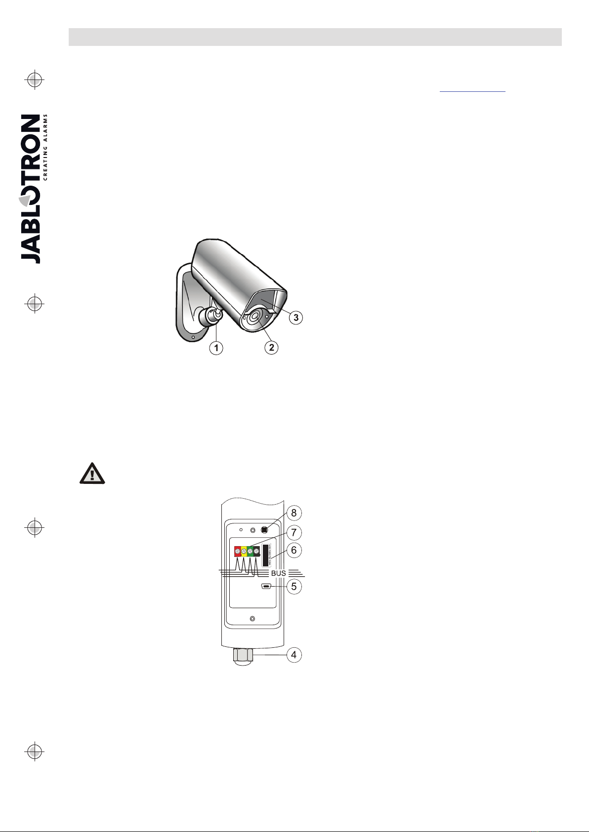
The JA-110C BUS photo verification camera
The JA-110C BUS photo verification camera 2 / 2 MNT51102
Note: A photo taken by a PG output activation is sent as the first, photos
taken before an activation are sent subsequently and photos after the
activation sent last. In the MyJABLOTRON app photos are displayed in
the order they were taken.
Tampering detector (tilt detector): (*Enabled) This option can disable
the reporting of a tamper alarm to the control panel in the case of
tampering with the camera (it does not have any influence on the tamper
contact on the camera cover). It can be used for problematic windy
locations to eliminate false alarms. However, by disabling the parameter
you risk the camera being turned to another direction without it being
reported to the system. In such a case we recommend you to enable the
parameter “Tamper-activated photos”.
Tamper-activated photos: (*Enabled) This option can disable taking
and sending photos in the case of camera tampering. When “Photo
buffering” is disabled and the tilt detector is activated, the camera takes 3
photos with a 5 s pause between them. When that parameter is enabled
the camera takes and sends photos according to the pre-set mode
(respects its settings fully – number of taken photos, time interval, etc.).
Note: Sometimes it could happen that photos will be taken at the same
time (duplication). This is determined by the camera’s internal algorithm.
IR supplementary illumination: (*Auto) The automatic function of
illumination by IR LED diodes of the camera is set in such a way that if the
ambient illumination drops below a certain level (dusk/sunset), the
illumination is automatically enabled. As soon as the ambient illumination
level increases (sunrise), the illumination is disabled. If the function “Pre-
PG-Activation photos” is “OFF”, the IR illumination is only activated on
triggering of the PG and for photos taken after the PG triggering. If “Always”
is selected, IR illumination will be permanently on. IR illumination can also
be completely disabled (we recommend it when camera is place in an
outdoor housing).
Higher IR illumination level: (*Disabled) This option allows you to
increase the IR LED diode lighting intensity level.
Warning: the increase of the intensity level will cause a higher
consumption from the BUS (by up to 150 mA – 250 mA), you should check
the total consumption from the BUS to maintain the backup of the system.
External device triggering: (*Disabled) When the option is enabled the
camera can use its internal illumination detector to trigger the PG. Select
the PG output in the camera internal settings in the Devices tab. By moving
the value between 0 (dark) and 10 (light) on the scale you determine under
what illumination conditions the PG is to be activated. To set the correct
level for particular illumination you can use the PG activation indicator
located next to the scale. When PG is ON the indicator goes red and when
the PG is OFF the indicator goes green.
Note: The controlled PG must have the “Copy” function (can be set in the
PG outputs tab).
Test: It takes a one test photo in LQ and shows it in F-Link. Then when
you click on the Detail button photos are displayed in HQ. Photos are
simultaneously sent to the external mass storage area (if transfers are
enabled).
Saving and browsing the pictures
Some photos (activation photos which are not in Photo buffering mode
and photos taken when after PG has been triggered in Photo buffering
mode) are taken as a double exposure: the first with low resolution
(LQ=320x240 pixels), second with high resolution (HQ=640x480 pixels).
All exposures are saved in the internal memory (built-in SD card) into the
independent folders Foto_LQ and Foto_HQ. When the card is fully loaded,
the oldest photos are replaced by new ones. Photos saved on the SD card
can be browsed by a normal PC browser when the camera is connected via
a USB cable.
Photos are sent to the control panel in LQ. You can browse through the
images by F-Link and J-Link software (in the Event memory, click on event
New image). Pictures are displayed in LQ, if you click on Detail you can get
pictures of the second exposure HQ (if existing). Images can be searched
and browsed by a file manager or picture browser. For another option to
show the pictures it is necessary to start F-Link (J-Link) software and be
logged into the control panel as a service technician or Administrator and
then under Disc: Flexi_log/Foto photos are available which have been sent
to the control panel (LQ) and photos which have been requested in Detail
(HQ).
Note: Some antivirus software writes checking data on the micro SD card.
The camera notices unknown files (the checking data) so formatting the SD
card will be performed. SD card formatting erases all data which has been
saved on the SD card.
Picture transmission from the control
panel to the MyJABLOTRON
If there is a SIM card supplied by the distributor and if the user uses
MyJABLOTRON services, then access to photos is automatically allowed.
Settings of the control panel for transferring pictures are done when the
panel is registered. All the photos are saved and visible in the
MyJABLOTRON application. The MyJABLOTRON application has an option
to fill in telephone numbers (for SMSes) or e-mails to get the photos when
they are taken (Notification). Using MyJABLOTRON it is also possible to
request a new picture without PG output activation (see Installation
recommendations).
Note: If the user doesn´t use or want to use the MyJABLOTRON
application, sending pictures straight from the control panel will work
normally. The control panel sends an SMS report to all selected users
according to the F-Link software, Users reports tab, Alarm photo settings.
Sent SMSes include an http link for displaying the photo, which on cell
phones with an internet connection can be displayed directly.
CAUTION: Because this camera allows you to take photos when the
system is unset by a PG state or from MyJABLOTRON, the producer strictly
warns the user that the camera has to be used within the limits given by
particular laws or norms, especially norms about the protection of personal
privacy.
The use of the camera is also subject to regulations on the protection of
personal data and the producer recommends that users should be aware of
the obligations applicable to the operation of CCTV.
According to these regulations MyJABLOTRON users have an obligation
to ensure the approval of persons in the range of the camera during the
acquisition of photos or the obligation to indicate the image capture area by
information signs.
Installation recommendations
Several JA-110C cameras can be installed in the system. When several
cameras are triggered at the same time, the transmission time to the
control panel and outward is extended. A whole transmission can take a
few minutes. It is also necessary to pay attention to the current peak
from the control panel when requesting the new photo by triggering
more cameras with an external IR illumination (all at the same time).
For taking photos by PG status set PG outputs / Function Impulse to a
time of at least 15 sec. via F-Link software. The camera has an internal
algorithm which limits taking the photos by PG status to 3 photos per
10 minutes.
The camera has no internal counter of photos taken in a day. The only
limitation to the number of photos taken by a PG output is a limit of 3
photos per 10 minutes.
Before you start using the MyJABLOTRON application or external mass
storage area check the cost of GPRS transfers with your GSM provider.
If several PG outputs have been triggered at the same time or getting
buffered photos is being performed, the camera uses already taken
pictures so they could be duplicated. The MyJablotron application
copies these photos subsequently to the correct events (switched PG
outputs).
Technical specifications
Power from the control panel BUS +12 V (+9 ... +15 V)
Current consumption in standby mode 15 mA
Current consumption for cable choice (IR higher intensity) 250 mA
IR illumination angle 70°
Horizontal camera capture angle 75°
Range of IR illumination max. 12 m
Resolution of the camera LQ 320*240; HQ 640*480 pixels
Average photo file size LQ/HQ (typically) 6kB / 35kB
Typical (LQ) photo transmission time to the control panel
up to 20 sec. (10 sec.)
Typical (LQ) photo transfer time from the system to server
15 s / GPRS; 2s / LAN
Operational environment according to EN 50131-1 IV. Outdoor general
Operational temperature range -20 to +60 °C, humidity max. 75%
IP cover IP65
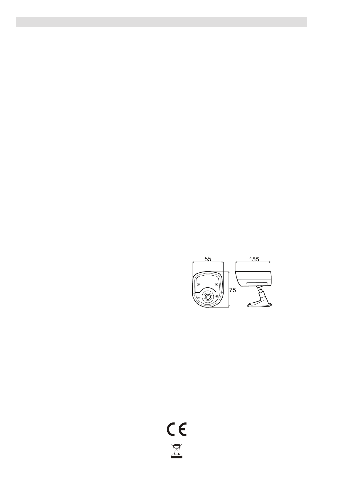
Dimensions, weight 155 x 75 x 55 mm, 235g
Classification Grade 2
According to EN 50131-1, EN 50131-3
Also complies with EN 50130-4, EN 55022
JABLOTRON ALARMS a.s. hereby declares that the JA-110C is
in compliance with the essential requirements and other relevant
provisions of Directive 2004/108/EC. The original of the conformity
assessment can be found at www.jablotron.com - Technical
Support section
Note: Although this product does not contain any harmful materials
we suggest you return the product to the dealer or directly to the
producer after use. For more detailed information visit
www.jablotron.com.