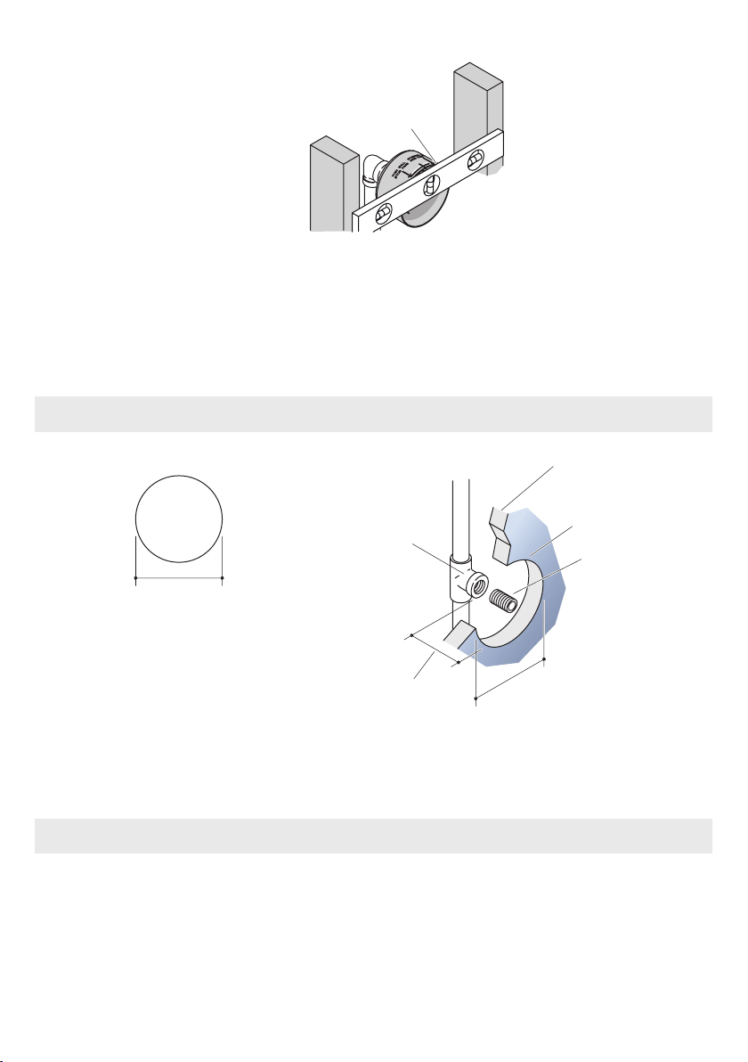
Jacob Delafon E8014 User manual

N O T I C E T E C H N I Q U E
I N S T R U C T I O N S
I N S T R U C C I O N E S
ИНСТРУКЦИЯ ПО ЭКСПЛУАТАЦИИ
E8014 E8013
Une marque de la Société KOHLER FRANCE - 330 339 144 RCS BOBIGNY
Siège Social : Immeuble Le Cap - 3, rue de Brennus
93631 La Plaine St Denis cedex
TEL. : 33 (0) 1 49 17 37 37 - FAX : 33 (0) 1 49 17 37 40
www.jacobdelafon.fr
www.jacobdelafon.es
SERVICE ASSISTANCE CLIENTÈLE : 0810 307 000
SAT ESPAÑA Y PORTUGAL: 902 11 38 36


Table des matières
Merci d’avoir choisi JACOB DELAFON ...........................................4
Avant de commencer ......................................................................4
Dimensions .....................................................................................4
Recommandations ..........................................................................4
Outillage nécessaire à l’installation .................................................5
1. Installation de la tuyauterie d’alimentation ...................................5
2. Installation de la boîte à plâtre ....................................................6
3. Réglage de la profondeur de la tuyauterie...................................6
4. Installation dans le mur fini..........................................................7
5. Vérification de la profondeur et installation du mamelon .............7
6. Installation de l’adaptateur...........................................................8
7. Installation du passage d’eau ......................................................8
8. Installation de l’applique ..............................................................9
Remédier à un débit d’eau réduit................................................... 10
Pièces de rechange ...................................................................... 11
Français

4Français
Dimensions
Nous apprécions votre engagement envers la qualité JACOB DELAFON. Veuillez
prendre s’il vous plaît quelques minutes pour lire ce manuel avant de commencer l’ins-
tallation. Ne pas hésiter à nous contacter en cas de problème d’installation ou de per-
formance. Nos numéros de téléphone et notre adresse du site internet sont au verso.
Merci encore d’avoir choisi la société JACOB DELAFON.
Merci d’avoir choisi JACOB DELAFON
Avant de commencer
Respecter tous les règlements de plomberie et de bâtiment locaux.
Inspecter la tuyauterie d’alimentation de tout dommage. Remplacer si nécessaire.
JACOB DELAFON se réserve le droit d’apporter toutes modifications au design des
robinets et ceci sans préavis, comme spécifié dans le tarif Jacob Delafon.
E8014 E8013
Recommandations
Pressions
• La pression minimale recommandée de fonctionnement est de 1 bar statique.
• Pour une performance optimale, une pression minimum de fonctionnement de 3 bars
statiques est recommandée ainsi qu’une pression maximum de 6 bars statiques. Au
delà, nous vous conseillons d’installer un réducteur de pression.
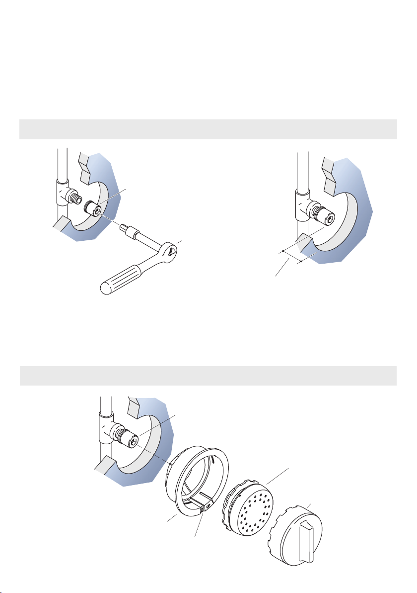
Installation
• L’installation nécessite une profondeur d’encastrement disponible de 95 millimètres.
Toutefois, nous vous recommandons une profondeur minimale de 100 millimètres afin
de faciliter votre installation.
Revêtement
• La finition de cet équipement de douche exige une attention particulière : pour conser-
ver son aspect, nettoyer régulièrement sa surface avec une éponge savonneuse non
abrasive, bien rincer et essuyer avec un linge doux. Eviter formellement l’utilisation des
produits contenant de l’alcool méthylique, des acides, des solvants ou des abrasifs qui
endommageraient le revêtement.
64 mm
57 mm
95 mm
G 1/2’’
102 mm 124 mm

5
Français
Outillage nécessaire à l’installation
1. Installation de la tuyauterie d’alimentation
• Acheminez les lignes d’alimentation en eau.
• Si plusieurs douchettes sont installées sur une même ligne d’alimentation, construire
une boucle de régulation et installer un Té pour réaliser une boucle à chaque empla-
cement de douchette.
• Ne pas fixer les tuyaux à ce moment.
Installation multiple
Boucle de régulation
de pression
Alimentation
en eau
Mamelon
Douille de 7/16” fournie.
Clé à cliquets, rallonge
Ruban d’étanchéité Niveau
Scie cloche
Perceuse
Mamelon
Installation d’une seule douchette
• Acheminez la ligne d’alimentation en eau.
• Installez un coude à l’extrémité du tuyau d’alimentation au niveau de la douchette.

6Français
2. Installation de la boîte à plâtre
• Installez la boîte à plâtre.
• Pressez jusqu’à ce que la boîte à plâtre soit contre la face du coude (ou du Té).
3. Réglage de la profondeur de la tuyauterie
REMARQUE :
Les installations en cloison mince ont une épaisseur au mur fini de moins
de 10 mm.
• Pour ajuster la profondeur du tuyau, utilisez un niveau ou autre rebord droit pour ali-
gner la marque ″thin wall″ (mur mince) avec la face avant des montants.
Installation en cloison mince
Coude (ou Té)
Boîte à plâtre
Alignez la marque ″thin wall″ avec
la face avant du montant
Toutes les installations
• Installez temporairement un mamelon à chaque Té ou coude. Ne pas utiliser de
mastic.
• Présenter, monter les tuyaux, sans les fixer à ce moment.

7
Français
• Pour ajuster la profondeur du tuyau, utilisez un niveau ou autre rebord droit pour ali-
gner le rebord de la boîte à plâtre avec la face avant des montants.
Toutes les installations
• Installez un renfort approprié et attachez les tuyaux à la profondeur ajustée.
Installation en mur standard
Alignez la marque ″standard wall″
avec la face avant du montant
4. Installation dans le mur fini
• Utilisez un matériau de mur résistant à l’eau.
• Faites une découpe de 10,5 cm, centré sur le mamelon du tuyau à chaque emplace-
ment d’installation de la douchette.
• Posez le matériau du mur fini.
10,5 cm
Mur fini
5.7 cm mini
Mamelon
Té ou coude Découpe
10,5 cm
Découpe
• Retirez le mamelon.
REMARQUE : La distance minimum entre l’avant du Té ou du coude et la surface du
mur fini doit être de 5,7 cm.
• Mesurez la distance de l’avant du Té ou du coude à la surface du mur fini. Réalisez
les ajustements nécessaires.
5. Vérification de la profondeur et installation du mamelon

8Français
Installer le mamelon
• Vissez le mamelon dans le Té ou le coude et serrez à la main.
• Mesurez la distance de l’extrémité du mamelon à la surface du mur fini. Vérifiez
que la distance soit entre 3,8 cm et 5,1cm.
• Retirez le mamelon.
• Appliquez un ruban d’étanchéité sur le filetage du mamelon.
• Installez à nouveau le mamelon sur le Té ou le coude.
• Par un écoulement d’eau, éliminez débris et impuretés.
6. Installation de l’adaptateur
7. Installation du passage d’eau
Cache-protecteur
Passage
d’eau
Repère
Outil pour le
passage d’eau
Clé à cliquets
avec rallonge
Adaptateur
2,2 mini
3,5 maxi
• Installez l’adaptateur sur le mamelon en utilisant une clé à cliquets avec une
rallonge, une douille de 11 et la mèche de 11 mm fournie.
• Mesurez la distance de la face de l’adaptateur à la face du mur fini. Vérifiez que la
distance soit au moins de 2,2 cm et pas plus de 3,5 cm. Faites les réglages si néces-
saire.
Adaptateur

9
Français
• Orientez le cache protecteur avec le repère vers le bas.
• Insérez le cache protecteur à l’intérieur de la découpe.
IMPORTANT! Si le passage d’eau ne peut pas être vissé sur l’adaptateur, retirer le
mamelon du tuyau et en installer un plus long.
En utilisant l’outil de passage d’eau fourni, vissez le passage d’eau sur l’adaptateur.
ATTENTION: Garder l’outil d’installation du passage d’eau. Cet outil est nécessaire
pour retirer le passage d’eau pour le nettoyage ou le dépannage.
• Vérifiez que le passage d’eau soit centré dans le cache protecteur.
IMPORTANT! Si le cache protecteur est desserré après l’installation du passage
d’eau, retirez le mamelon du tuyau et installez-en un plus court.
• Vérifiez que le cache protecteur soit positionné avec le repère vers le bas. Il doit s’in-
sérer dans la découpe et ne pas bouger.
8. Installation de l’applique
Applique
Cache-protecteur
Centrer l’ouverture avec la marque
Repère
• Localisez le repère sur l’applique.
• Positionnez l’applique sur le cache protecteur avec la marque centrée dans l’ouver-
ture du repère de l’applique.
• Pressez l’applique sur le cache protecteur et tournez vers la droite pour le fixer.
• Vérifier que le repère du cache protecteur soit aligné avec le repère de l’applique.

10 Français
Remédier à un débit d’eau réduit
Si vous constatez que la débit d’eau de la douchette est réduit, essayez ce qui suit:
Nettoyer les buses de la douchette
• Pendant que l’eau coule, frottez fermement le doigt sur les buses du vaporisateur
pour déloger tout débris ou dépôt minéral. Si ceci n’améliore pas le débit d’eau,
procédez à ″Nettoyer le filtre″
Nettoyer le filtre
• Tournez l’applique vers la gauche pour la retirer.
• Avec l’outil de passage d’eau (fourni), retirez le passage d’eau.
• Avec une clé à cliquets avec une rallonge et la mèche fournie de 11 mm, retirez
l’adaptateur.
• Avec un petit tournevis plat, retirez délicatement le filtre de l’adaptateur.
• Frottez gentiment la rondelle sous l’eau courante afin de retirer tout débris.
• Réinstallez la rondelle dans l’adaptateur.
• Réinstallez l’adaptateur, le passage d’eau et l’applique comme indiqué dans ce ma-
nuel.
Applique
Passage
d’eau
Adaptateur
Filtre

11
Français
Pièces de rechange
E8013
E8014
R8A693NF
R8A692NF
R8A691NF
R8A691NF
R8A690NF
R8A694NF
R8A698NF
R8A696NF
R8A699NF
E8A697-CP
E8A700-CP


English
Contents
Thank you for choosing JACOB DELAFON .................................. 14
Before you begin ........................................................................... 14
Dimensions ................................................................................... 14
Recommandations ........................................................................ 14
Necessary tools ............................................................................ 15
1. Install the supply piping ............................................................. 15
2. Install the plaster guard ............................................................. 16
3. Set the pipe depth ..................................................................... 16
4. Install the finished wall .............................................................. 17
5. Verify depth and install the nipple.............................................. 17
6. Install the adapter...................................................................... 18
7. Install the waterway ................................................................... 18
8. Install the escutcheon ............................................................... 19
Remedy reduced water flow..........................................................20
Service parts................................................................................. 21

14 English
Dimensions
We appreciate your commitment to JACOB DELAFON quality. Please take a few minu-
tes to review this manual before you start installation. If you encounter any installation
or performance problems, please don’t hesitate to contact us. Our phone numbers and
website are listed on the back cover. Thanks again for choosing JACOB DELAFON
Company.
Thank you for choosing JACOB DELAFON
Before you begin
Observe all local plumbing and building codes.
Inspect the supply piping for damage. Replace as necessary.
JACOB DELAFON reserves the right to make revisions in the design of faucets without
notice, as specified in the Price Book.
E8014 E8013
Recommandations
Pressures
• The minimum recommanded operating pressure is 1 bar static.
• For an optimal performance, a minimum operating pressure of 3 bars static is recom-
manded and a maximum pressure of 6 bars static. Beyond that, we advise you to install
a pressure reducing control valve.
Installation
• The installlation requires an available depth of mounting of 95 millimeters. However,
we advise you a mininal depth of 100 millimeters to facilitate your installation.
Covering
• The finish of this shower equipment requires special care. To maintain its shine and
luster, clean regularly with a non-abrasive sponge and soap, rinse thoroughly and dry
with a soft cloth. Do not use harsh products containing methyl alcohol, acids, solvents
or abrasives that can damage the finish.
64 mm
57 mm
95 mm
G 1/2’’
102 mm 124 mm

15
English
Necessary tools
1. Install the supply piping
• Install the water supply pipes.
• If installing more than one bodyspray off the same supply line, construct a pressure
balancing loop. Locate a tee along the loop at each bodyspray installation location.
• Do not fix the pipework at this time.
Multiple bodyspray installation
Pressure
Balancing Loop
Water supply
Nipple
Socket Wrench with
7/16’’ Socket and Ex-
tension
Sealant Tape Level
Hole Saw
Drill
Nipple
Single bodyspray installation
• Route the water supply line.
• Install an elbow to the end of the supply pipe at the bodyspray installation location.
• Do not strap the pipes at this time.

16 English
2. Install the plaster guard
• Install the plaster guard.
• Push until the plaster guard is snug against the face of the elbow (or tee)
3. Set the pipe depth
NOTE : Thin wall installations have a finished wall thickness of less
than 1/2″ (1.3 cm).
• To adjust the pipe depth, use a level or other straight edge to line up the ″Thin Wall
Installation″ mark with the front face of the studs.
Thin wall installation
Elbow (or Tee)
Plaster guard
Align mark with the front of
the stud face.
All installations
• Temporarily install a nipple to each tee/elbow. Do not use any sealant.
• Do not strap the pipes at this time.

17
English
• To adjust the pipe depth, use a level or other straight edge to line up the edge of the
plaster guard with the front face of the studs.
All installations
• Install appropriate backing and strap the pipes at the adjusted depth.
Standard wall installation
Align mark with the front of
the stud face.
4. Install the finished wall
• Install the water-resistant wall board.
• Cut out a 10.5 cm round hole, centered on the pipe nipple at each desired installation
location.
• Install the finished wall material..
10,5 cm
Finished wall
5.7 cm mini
Nipple
Tee or elbow Cutout
10,5 cm
Cutout
• Remove the nipple.
REMARQUE : The minimum distance between the face of the tee/elbow and the sur-
face of the finished wall should be 5.7 cm.
• Measure the distance from the face of the tee/elbow to the surface of the finished
wall. Make any adjustments as needed.
5. Verify depth and install the nipple

18 English
• Install the nipple.
• Thread the nipple into the tee/elbow and hand tighten.
• Measure the distance from the end of the nipple to the surface of the finished wall.
Verify that the distance is at least 3.8 cm and no more than 5.1 cm.
• Remove the nipple.
• Apply thread sealant to the threads of the nipple.
• Reinstall the nipple to the tee/elbow.
• Run water through the system to flush out any dirt or debris.
6. Install the adapter
7. Install the waterway
Protector guard
Waterway
Drain Port
Waterway tool
Socket wrench
with bit
Adapter
2,2 mini
3,5 maxi
• Install the adapter to the pipe nipple using a socket wrench with extension, 11 mm
socket, and the provided 11 mm bit.
• Measure the distance from the face of the adapter to the face of the finished wall.
Verify the distance is at least 2.2 cm and no more than 3.5 cm. Make any adjustments
as needed.
Adapter

19
English
• Orient the protector guard with the drain port down.
• Insert the protector guard into the rough opening.
IMPORTANT! If the waterway cannot be threaded onto the adapter, remove the pipe
nipple and install a longer one.
• Using the provided waterway tool, thread the waterway to the adapter.
NOTICE: Keep the waterway installation tool. This tool is needed to remove the
waterway for cleaning or servicing.
• Verify the waterway is centered in the protector guard.
IMPORTANT! If the protector guard is loose after the waterway is installed, remove
the
pipe nipple and install a shorter one.
• Verify the protector guard is still positioned with the drain port down. The protector
guard should be snug to the wall and not move or shift.
8. Install the escutcheon
Escutcheon
Protector guard
Center the opening with mark.
Drain port
• Locate the drain port on the escutcheon.
• Position the escutcheon on the protector guard with the mark on the protector guard
centered in the escutcheon drain port opening.
• Press the escutcheon onto the protector guard and turn clockwise to secure.
• Verify the drain port in the protector guard is aligned with the escutcheon drain port.

20 English
Remedy reduced water flow
If you are experiencing reduced water flow from your bodyspray, try one of the
following:
Clean the Spray Nozzles
While the water is running, firmly rub your finger across the spray nozzles to
dislodge any debris or mineral build-up. If this does not improve water flow,
proceed to ″Clean the Screen Washer.″
Clean the Screen Washer
• Turn the escutcheon counterclockwise to remove.
• Using the waterway tool (provided), remove the waterway.
• Using a socket wrench with extension and the provided 11 mm bit (or a 11 socket)
remove the adapter.
• Using a thin-blade screwdriver, carefully pry the screen washer from the adapter.
• Gently rub the washer under running water to remove any debris.
• Reinstall the washer into the adapter.
• Reinstall the adapter, waterway and escutcheon; refer to the ″Install the Adapter,″
″Install the Waterway,″ and ″Install the Trim″ sections.
Escutcheon
Waterway
Adapter
Filter
This manual suits for next models
1
Table of contents
Languages:
Other Jacob Delafon Bathroom Fixture manuals