This kit is intended for use with Eclipse 322™riding greens
mowers.
1. Park the mower on a flat and level surface, verify the
parking brake is engaged, turn the ignition switch to
the OFF position, and remove the key.
a. Wait for all movement to stop before making any
adjustments or modifications.
b. Allow sufficient time for the unit to cool down.
c. Take this opportunity to thoroughly inspect the
equipment and perform other required maintenance.
2. If this kit is to be added to a reel without a Turf
Groomer™ installed, counterweight kit 4261251 must
be installed before proceding. The counterweight kit is
not included with this kit, and must be ordered
separately.
Preparation ___________________________________________________________________
1. Remove reels from Eclipse 322 mower. Refer to the
mowers Parts & Maintenance manual.
a. Disconnect battery power connector(s).
b. Disconnect reel motor connections. Remove any
cable ties securing wire harness to reel or lift yokes.
c. Remove yoke cap and pin.
d. Lift up on lift arm, and slide reel out and away from
mower.
2. Move reel to work bench.
3. If the Bi-Directional Groomer/Brush or the Turf
Groomer is installed, proceed with Rear Roller Brush
Assembly.
4. If the Bi-Directional Groomer/Brush or the Turf
Groomer is to be installed at this time, install the the Bi-
Directional Groomer/Brush or the Turf Groomer first,
then proceed with Rear Roller Brush Assembly.
5. If the Bi-Directional Groomer/Brush or the Turf
Groomer is not installed, install counterweight kit
4261251, using instructions included in counterweight
kit.
Rear Roller Brush Assembly With Bi-Directional Groomer/Brush _______________________
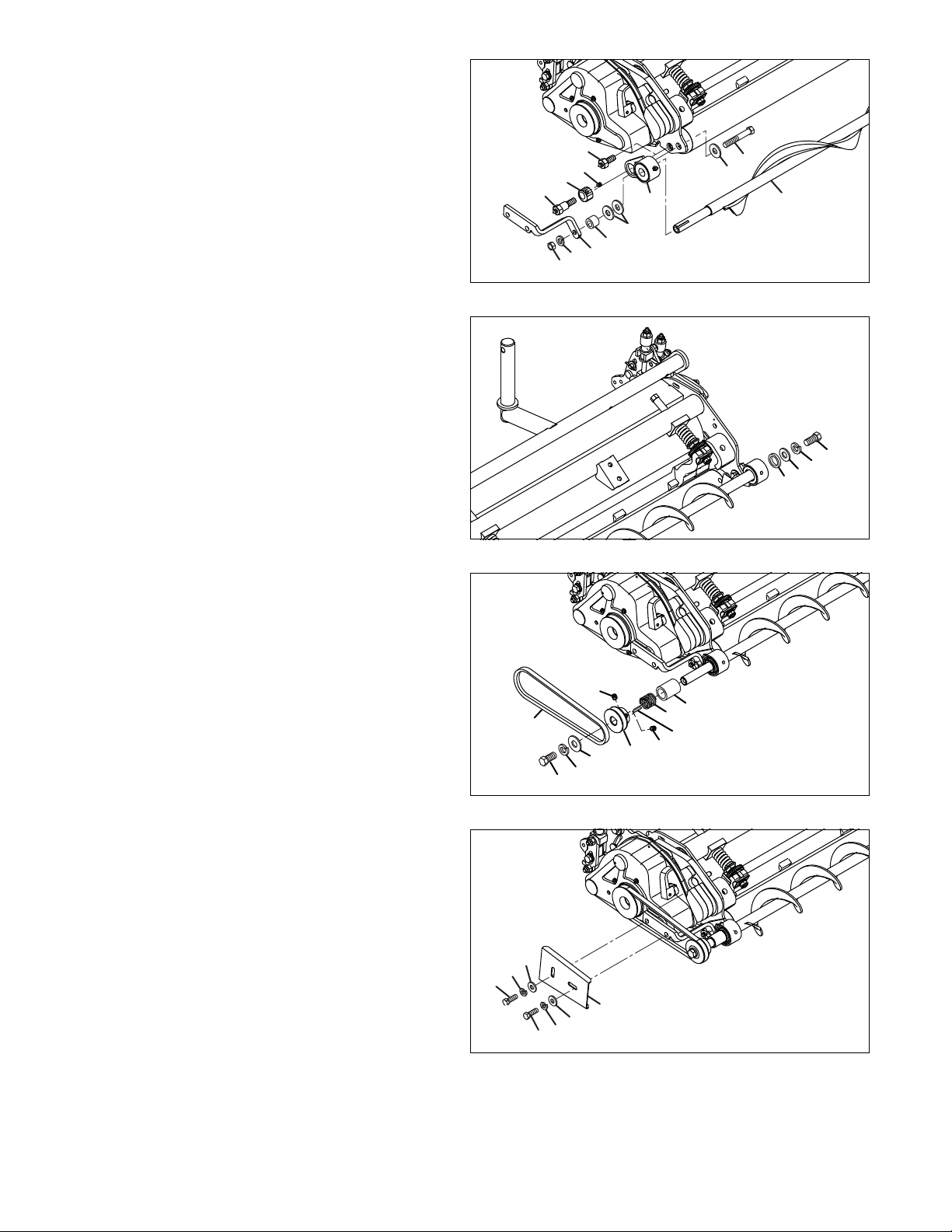
1. Remove and discard zerk bolt (A) from motor end of
reel.
2. Loosely assembly set screw (Item 1) into eccentric nut
(Item 2).
3. Slide eccentric nut (Item 2) onto shoulder zerk bolt
(Item 3).
4. Assemble shoulder zerk bolt (Item 3) through bearing
housing (Item 4) and reel frame into rear roller.
NOTE: There are two different sizes of zerk bolts included
in kit. Use the 3/8-24 shoulder zerk bolt for standard rear
roller, or 7/16-20 shoulder zerk bolt for heavy duty rear
roller.
5. Loosely secure bearing housing (Item 4) to reel frame
using one 5/16-18 x 1-1/4” screw (Item 5), two flat
washers (Item 6), one lockwasher (Item 7), and one
nut (Item8).
6. Slide rear roller brush (Item 9) into housing.
Figure 1
CAUTION
Before you install this kit, read the mower’s manuals to
become familiar with the mower, the controls, and
proper use of the equipment.
Stay alert for potential hazards and follow all safety
precautions. Read all instructions completely and make
sure you understand them before proceeding with the
assembly.
WARNING
Before you attempt to clean, adjust, or repair any of this
equipment, disengage all drives, shut down the engine
and allow the unit to cool. Remove the key from the
ignition switch to prevent accidental starting and
potential bodily injuries.
INSTRUCTION SHEET
Rear Roller Brush Kit 62818
Litho in U.S.A. 2-2014 Part No. 4226620-Rev C