Jameco 2170521 User manual

POCKET SIZED GUITAR AMPLIFIER | JAMECO PART NO. 2170521
One of the biggest pains of an electric guitar is the need to hook it up to an amp to hear actual electric guitar sound. That’s not a
problem with the milli-AMP! The milli-AMP uses a bridged ML386N-3 amplifier circuit to produce in the neighborhood of two watts
output power. It runs of a rechargeable 9 volt battery that provides an hour of full volume play per charge. At two watts, the milli-AMP is
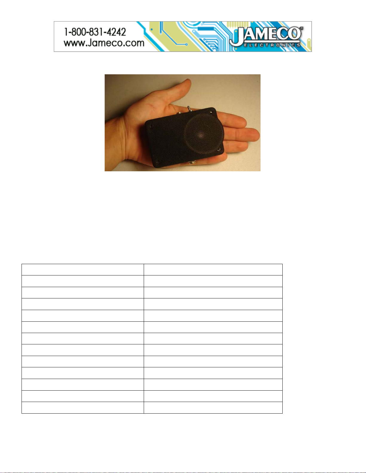
more powerful than any commercially available amp (that I know of) of its size; its size being a very pocketable 2.25 by 3.5 by 1 inches
(roughly). Volume is controlled by the volume pot on the guitar, and controls distortion as well.
Experience Level: Intermediate | Time Required: 3-6 hours
Required tools and parts:
Case for the charger circuit: I used a case from an Ipod Nano.
Bill of Materials:
IC LM317 ICLM386
Transformer Capacitor, 0.22uF
Capacitor, 10uF Capacitor, 0.05uF
Battery,8.4 V Audio Connector
Toggle Switch Capacitor, 100uF
DC Power Plug, female DC Power Jack, male
Plastic Cases Battery Snaps
Prototype board Solid wire
Capacitor, 1000uF Resistors, 240 OHM
Resistors, 1.5 K Resistors, 1.5 M
Transistor Speaker
Potentiometer, 500 OHM, single turn Wall transformer
Resistors, 470 OHM Resistors, 10 OHM
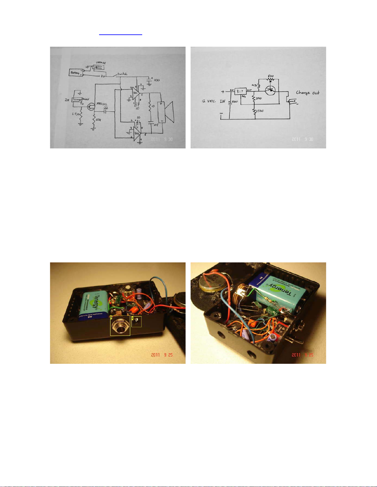
Step 1 – Schematics

The first schematic is for the amp. It has been modified from runoffgroove.com to allow for a switch and the charging jack. The original
schematic can be found on the runoffgroove.com website. The second schematic is of the charger. The transistor in the charger
schematic is the BC327 or equivalent.
Step 2 – Assemble the Amp
One thing that might be a good idea is to build each amplifier with its own independent circuit (each amp has its own separate
connection to ground, positive battery supply, input, etc.) The purpose is to allow a blown amplifier chip to be removed and replaced
without disturbing the other chip.
Pay special attention to the polarity of the charging jack. The center pin should be positive, with the sleeve contact being negative. As
for the enclosure, a hole has to be drilled in one side for the enclosure for the input jack, then two holes on the opposite side for the
switch and charging jack.
If you want to add an optional clip to the back you will want to drill that hole now as well. Two holes, each 1/4" in diameter, should be
drilled on the narrow end of the enclosure near the speaker, as well as two other holes opposite each other on the sides adjacent to the
previously mentioned side. These act purely as ports for the speaker.
1.Port
2.Input jack
As for the speaker place it face down on the top of the enclosure, and a knife used to score a circle around the edge. I used a 1" spade
bit to drill out the middle of the circle then used a dremel with a sanding drum to enlarge the hole so the speaker would fit comfortably.
The speaker does not have any mounting hardware so you need to glue into place.

1. Make sure nothing is touching here
Once the circuit is built placed it in the enclosure. The battery goes at one end, with the two jacks next to the battery opposite each
other, and the switch and amplifier circuit mounted underneath the speaker. Since the speaker has a relatively shallow mounting depth,
there is enough room for two small heat sinks to be placed on top of the amplifier chips.
1. Part of the circuit built onto speaker itself
(Blue dot represents positive connection)
The heatsinks are cut up pieces of a regular heatsink filed down to fit. They were then glued to the amplifying chips using a homemade
"thermal glue" of JB Weld mixed with aluminum shavings. I know not ideal, but it's better than not having any heatsink at all.
1. Port
2. Power switch
3. Charging jack
Make sure nothing touches the plug tip or its connections. The screw near the green cap is for the clip. The plug is not touching the
screw.

1. Closeup of how speaker fits above amplifying circuit 1. Heat sinks
2. Ports
Step 3 – Amp: Finishing Touches - Optional
I chose to add a clip from an old tape measure to the back of the amp allowing the amp to be clipped to the strap on the guitar. For a
more professional appearance, the front of the amp is covered in grill cloth from an old pair of speaker grills.
White tubing about 1/4" in external diameter was glued around the speaker, and then the grill cloth stretched around it. Hot glue was
then used to adhere the edges of the cloth to the backside of the enclosure cover. Where the cloth was folded over on itself at the
corner, the tip of a hot soldering iron was used to poke hole in the backside for the screws. On the front, no holes were made, since the
screws could puncture the fabric.
Custom decals were made, and adhered to the back of the enclosure. To make these decals, the image was printed onto normal paper,
dipped in polyurethane and the excess scraped off. The decals were then placed on the enclosure, and the polyurethane left to dry
overnight. A red dot was added near the switch to signify the "on" position.
1. Front cover resting on top. It is not screwed on yet.

1. Hole made for screws 1. Red dot to mark ON position of switch
Step 4 – Assemble the Charger
After following the schematic provided in step 1, hook the charger up to the battery in the amp. This may be easier to do with the battery
removed. With an ammeter in series with the positive connection of the charger and positive connection of the battery, and the negative
connection of the charger hooked directly onto the battery.
With the charger plugged in, turn the trim pot until 30ma is read on the ammeter. Do not go above 30mA. This is the maximum safe
charging current for a NiMh battery of this size. Also, make sure that the center contact of the plug is positive, with the external sleeve
being negative.
An option you might want to follow is to mount the charger in an enclosure. Since the LM317 should be heatsinked, make sure the
enclosure is large enough to accommodate it.

Image Notes
1. 12 volts DC in
2. 9 volts DC out
3. The image above shows (2) 120 ohm resistors were used in the place of the 240 ohm resistor.
Step 5 – Completed Project
Before you use, there are a few notes about the use of the milli-AMP:
Do not turn the amp on without a guitar already plugged in. (A painful screech will occur hurting your ears)
Do not play the amp while charging. Charge only with the amp switched off.
To fully charge from a dead battery will take 12 hours. Do not overcharge the amp.
The volume is controlled by the volume pot on the guitar. Because the amp starts clipping above about half volume (entirely dependant
on your guitar) the volume also controls the distortion produced by the amp. With the volume turned down enough for the sound to be
clean, the "loudness" of the amp is not significantly lower. This depends on the guitar.