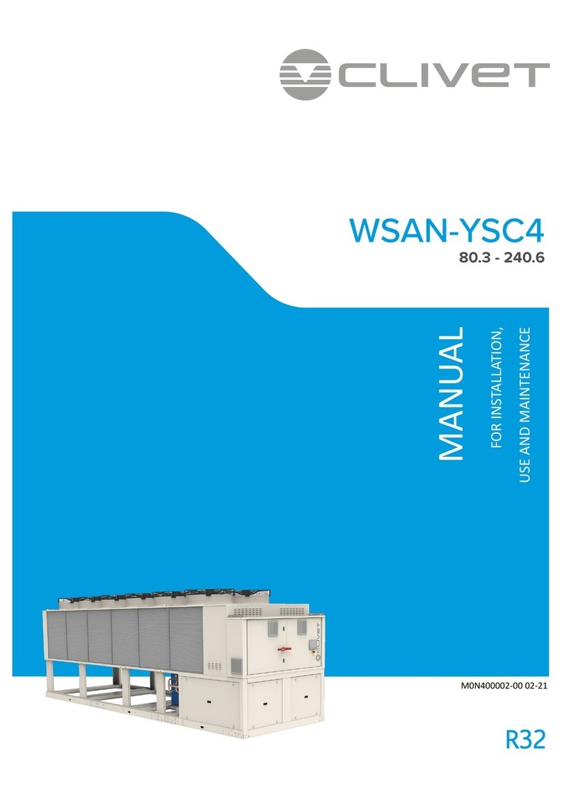
J&D MAnufacturing VPRF363 User manual

POLY CHILLER
IS230-12H J&D Manufacturing • 6200 Hwy 12 • Eau Claire, WI 54701 • 1-800-998-2398 • www.jdmfg.com Page 1 of 4
RECOMMENDED TOOLS FOR ASSEMBLY (NOT PROVIDED)
Safety Glasses
Socket Wrench Sockets
1/2”, 9/16”, 3/4”
Combination Wrenches
1/2”, 9/16”, 3/4”
PARTS LEGEND
Top Hanging Bracket
Side Hanging Brackets
Installation Bracket
Poly Chiller Fan
Please read over all instructions carefully before you begin.
If you have any questions please call your local dealer, or
contact J&D Manufacturing at 1-800-998-2398.
INSTALLATION
WARRANTY
J&D Manufacturing warrants all products are free from defects in materials and
workmanship under normal use for the period of one year from date of purchase.
Our warranty does not cover normal or regular wear and tear. J&D Manufacturing
can repair or replace at our option, any product or part of the product that is found
to be defective. Our warranty applies to materials only, and does not include return
freight, delivery, loss or damage to personal property, cost of removal or
installation, any incidental or consequential damages or labor. This warranty does
not apply to products which are misused, abused, altered, improperly installed or
subject to negligence. All warranties must be approved through our warranty
department. The original purchaser must present a copy of the invoice for the
defective product. One year is our standard warranty unless specified on our
literature or in the installation instructions or user manuals.
INCLUDED ASSEMBLY HARDWARE - TO SCALE
(4)
5/16”-18 x 1”
Carriage Bolt
(3)
3/8”-16 x 1-1/4”
Hex Bolt
(4)
5/16”-18
Nylock
Flange Nut
(3)
1/2”-13
Nylock Nut
(3)
3/8”-16
Nylock Nut
Tilt Bracket
(pre-assembled on fan)
INSTALLATION HARDWARE IS NOT PROVIDED
(3)
1/2”-13 x 1-1/2”
Hex Bolt

2
Attach the Top Hanging Bracket to the Side Hanging Brackets as shown
using (4) 5/16” - 18 x 1” Carriage Bolts and (4) 5/16” - 18 Nylock Flange
Nuts.
IS230-12H J&D Manufacturing • 6200 Hwy 12 • Eau Claire, WI 54701 • 1-800-998-2398 • www.jdmfg.com Page 2 of 4
1
Using the two pre-drilled holes on the rounded end of a Side Hanging
Bracket, attach to the Tilt Bracket on the side of the fan housing by
inserting (1) 1/2” - 13 x 1-1/2” Hex Bolt through the single bottom hole on
the Tilt Bracket, and the bottom hole on the Side Hanging Bracket. Secure
with (1) 1/2” - 13 Nylock Nut.
To further stabilize the Side Hanging Brackets and prepare for installation,
insert (1) 3/8” - 16 x 1-1/4” Hex Bolt through the top middle hole on the Tilt
Bracket, and through the top hole on the Side Hanging Bracket. Secure with
(1) 3/8” - 16 Nylock Nut. This fully upright position is best for installation.
Once the Poly Chiller is installed, you may remove the top Nut and Bolt and
reposition to adjust the fan tilt.
Repeat for the other Side Hanging Bracket.
3
IMPORTANT!! Before attaching the Installation Bracket to your structure,
you must insert (1) 1/2” - 13 x 1-1/2” Hex Bolt into the center mounting
hole as shown.
4
Attach the Installation Bracket to your structural beam or stud using
hardware (not provided) that is capable of supporting 150 lbs (68 kgs).

!WARNING !
DO NOT mount the Poly Chiller with the bracket to the side of the fan as
shown. The motor mount and fan mounting bracket are not structurally
designed to support the fan in this orientation. Mounting the Poly Chiller in
any way other than outlined in these installation instructions will void the
fan warranty, and may cause severe injury or even death.
IS230-12H J&D Manufacturing • 6200 Hwy 12 • Eau Claire, WI 54701 • 1-800-998-2398 • www.jdmfg.com Page 3 of 4
5
Once the Installation Bracket is secured to your structure, lift and attach
the Poly Chiller to the Installation Bracket by inserting the (1) 1/2” - 13 x
1-1/2” Hex Bolt through the hole in the Top Hanging Bracket. Secure using
(1) 1/2” - 13 Nylock Nut.
The Hex Bolt should be fully engaged with the Nylock Nut, and the brackets
should fit together tightly.
The top Installation Bracket is not used when mounting the Poly Chiller with
the optional mounting brackets.
To use the optional mounting brackets, complete Step 1 and 2 of the
standard installation. Secure the optional mounting bracket to a post or
wall using hardware (not provided) that is capable of supporting 150 lbs
(68 kgs). Lift and attach the Poly Chiller to the optional mounting bracket
by inserting (1) 1/2” - 13 x 1-1/2” Hex Bolt through the hole in the optional
mounting bracket and through the center hole in the Top Hanging Bracket
as shown. Secure using (1) 1/2” - 13 Nylock Nut. Proceed with Step 6 of
the standard installation instructions to tilt and rotate your fan.
OPTIONAL MOUNTING BRACKETS
6
Now that your Poly Chiller is securely installed to your structure, you may
remove the (1) 3/8” - 16 x 1-1/4” Hex Bolt and (1) 3/8” - 16 Nylock Nut
installed in the top tilt position in each Side Hanging Bracket in Step 1.
Tilt and rotate the fan to the desired position to direct airflow. Reinstall the
Nuts and Bolts in the Side Hanging Brackets to lock the vertical tilt
position. Lock the horizontal rotation of the fan by inserting (1) 3/8” - 16 x
1-1/4” Hex Bolt through one of the additional holes in the Installation
Bracket, and into one of the multi-position holes in the Top Hanging
Bracket. Secure with (1) 3/8” - 16 Nylock Nut.
VRSBRD36C
VRSBRD36C4
VRSBRD36B

IS230-12H J&D Manufacturing • 6200 Hwy 12 • Eau Claire, WI 54701 • 1-800-998-2398 • www.jdmfg.com Page 4of 4
7
6200 Hwy 12 • Eau Claire, WI 54701 • 1-800-998-2398
Visit our website at www.jdmfg.com
B
• Install manual disconnect switch inside building adjacent to
fan per national, regional,and local electrical codes.
• Route wire to motor with drip loop and secure. Drip loop will
drain accumulated moisture away from the motor.
• Configure internal wires to match supply voltage and wire
according to motor nameplate. Test to verify correct rotation.
• Only permit power to unit when shutter and guard is fully
installed to prevent injury.
Separate variable speed control is required to adjust fan speed.
Contact your dealer for more information.
MAINTENANCE INSTRUCTIONS
• Disconnect power before cleaning or maintaining your fan in order
to prevent serious injury or death.
• Service and repair of fan should only be completed by a qualified
technician.
• For maximum efficiency and fan life, keep the following free from
dirt and dust:
- blades
- housing
- motor
- guard
• The totally enclosed air over motor has sealed ball bearings and
does not require additional lubrication.
ALL ELECTRICAL WORK SHOULD BE
COMPLETED BY QUALIFIED PERSONNEL
AND MEET NATIONAL, REGIONAL
AND LOCAL CODES.
A• Plug cord into 115 AC grounded outlet that meets national,
regional and local codes.
• Route electrical cord from motor to outlet with drip loop.
Drip loop will drain accumulated moisture away from the
motor and outlet.
• Only permit power to unit when shutter and guard is fully
installed to prevent injury.
Separate variable speed control is required to adjust fan speed.
Contact your dealer for more information.
POWERING UNIT
The Poly Chiller fan is available with or without a pre-wired cord. If the
model you purchased includes an attached cord, proceed to step A for
instructions on powering your fan. If you purchased a model without a
cord, proceed to step B for wiring instructions.
Popular Chiller manuals by other brands
Pfannenberg
Pfannenberg EB Series Installation, operation and maintenance manual

Lava
Lava ATTILA GN 2/3 User and maintenance manual
SMC Corporation
SMC Corporation HRS030-A-20 series Original instructions
lancer
lancer DELTA II 9100 Series Installation and service manual
Parker Hiross
Parker Hiross Hyperchill ICE015 user manual
Advantage
Advantage BC-N4 Series instruction manual


