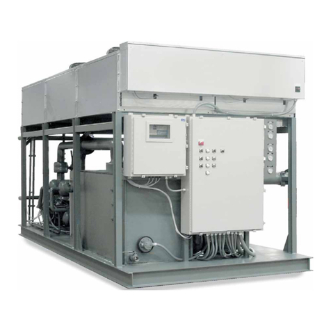
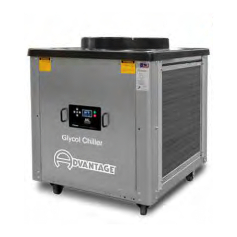
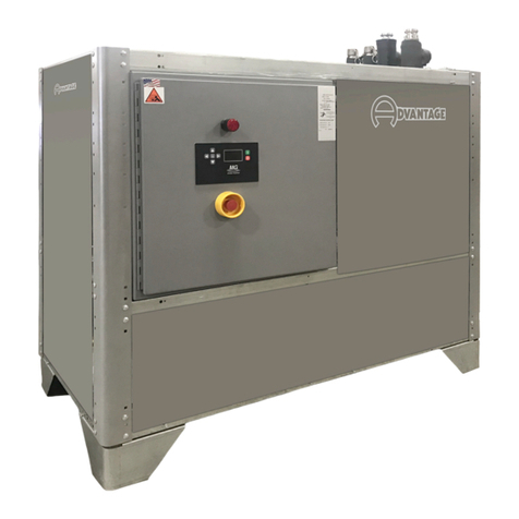
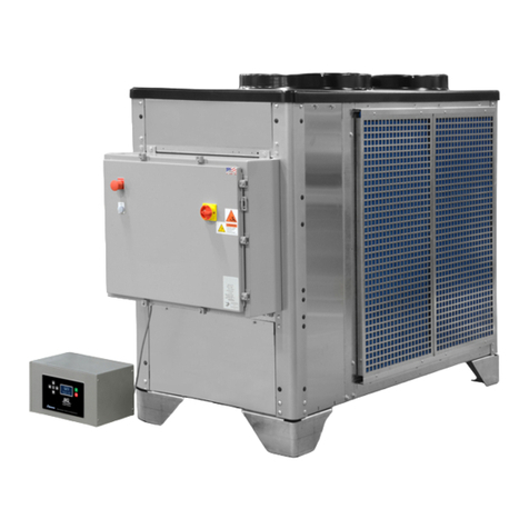
Advantage BC-N4 Series User manual

BC-N4 Series
Glycol Chiller
I.O.M. #139 updated 09/27/2016
INSTRUCTION MANUAL • INSTALLATION • OPERATION • MAINTENANCE
ADVANTAGE ENGINEERING, INC.
525 East Stop 18 Road Greenwood, IN 46142
317-887-0729 fax: 317-881-1277
Service Department fax: 317-885-8683
www.AdvantageEngineering.com
E-mail [email protected]
Covering 5, 7.5 and 10 horsepower
models with ‘M1’ Instruments &
Scroll Compressors
Model:
Serial Number :
Stop: If running at a uid temperature below 48°F or if the chiller will be installed in a climate
where the ambient temperature may get below 40°F you must use a water and glycol mixture
at a ratio that protects the uid from freezing to approximately 25°F below the lowest expected
set point temperature or the lowest expected ambient temperature whichever is lower. See
Section 8.1 and 8.2 of this manual before operating your chiller. Regular testing of your glycol
protection is critical.


INSTRUCTION MANUAL
With M1 INSTRUMENT
& SCROLL COMPRESSORS
AIR-COOLED MODELS
COVERING
INSTALLATION
OPERATION
MAINTENANCE
BC-N4 Series
Glycol Chiller
ADVANTAGE ENGINEERING, INC. 525 East Stop 18 Road Greenwood, IN 46142
317-887-0729 fax: 317-881-1277 Service Department fax: 317-885-8683

BC-N4 Glycol Chiller
Page: 4
ADVANTAGE ENGINEERING, INC.
525 East Stop 18 Road Greenwood, Indiana 46142
317-887-0729 Fax: 317-881-1277
Service Department Fax: 317-885-8683
Email: [email protected]
TABLE OF CONTENTS
1.0 GENERAL 7
1.1 Introduction 8
1.2 Safety 8
1.3 Receiving instructions 9
1.4 Efciency 9
1.5 Clean air act 10
1.6 Water Treatment 10
1.7 Components 11
2.0 INSTALLATION 13
2.1 General 14
2.2 Unit location 14
2.3 To and From process connections 15
2.4 Water supply connection 16
2.5 Air-cooled condenser 16
2.6 Electrical connection 17
3.0 OPERATIONS 21
3.1 General 22
3.2 Start up/operations procedure 22
3.3 Instrument/operation 28
3.4 Shut down procedure 32
4.0 TROUBLESHOOTING 33
4.1 Unit Will Not Start 34
4.2 Compressor Hums But Will Not Start 34
4.3 Shuts Off On High Pressure 34
4.4 Shuts Off On Low Pressure 35
4.5 Compressor Shuts Off On Internal Overload 36
4.6 Low Or No Process Pressure Or Water Flow 36
4.7 Cooling Capacity Inadequate 37
4.8 Sensor 37
4.9 Coolant Pump 37
4.10 Chiller Controller 37
5.0 MAINTENANCE 39
5.1 Warranty service procedure 40
5.2 Periodic preventative maintenance 40
5.3 Special maintenance 41
5.4 Solenoid valve service 42
5.5 Pump seal service 43
5.6 Checking the refrigerant charge 47
5.7 Proper cleaning procedure for brazed plate evaporators 47
6.0 COMPONENTS 49
6.1 Water system 50
6.2 Refrigeration system 51
6.3 Options 53

BC-N4 Glycol Chiller
Page: 5
ADVANTAGE ENGINEERING, INC.
525 East Stop 18 Road Greenwood, Indiana 46142
317-887-0729 Fax: 317-881-1277
Service Department Fax: 317-885-8683
Email: [email protected]
7.0 RELATED DRAWINGS 55
7.1 Mechanical Schematic : Air-Cooled : .25 - 1.5 Tons 56
8.0 APPENDIX 57
8.1 Operationsbelow48°Fuidor38°Fambient 58
8.2 Inhibited propylene glycol 60
8.3 Refrigerant pressure-temperature chart 61

Page: 6
THIS PAGE INTENTIONALLY BLANK

BC-N4 Glycol Chiller
Page: 7
ADVANTAGE ENGINEERING, INC.
525 East Stop 18 Road Greenwood, Indiana 46142
317-887-0729 Fax: 317-881-1277
Service Department Fax: 317-885-8683
Email: [email protected]
1.0 GENERAL
1.1 Introduction
1.2 Safety
1.3 Receiving Instructions
1.4 Efciency
1.5 Clean Air Act
1.6 Miscellaneous
1.7 Water Treatment
1.8 Components

BC-N4 Glycol Chiller
Page: 8
ADVANTAGE ENGINEERING, INC.
525 East Stop 18 Road Greenwood, Indiana 46142
317-887-0729 Fax: 317-881-1277
Service Department Fax: 317-885-8683
Email: [email protected]
1.1 INTRODUCTION
A. This manual covers portable chillers from 5, 7.5 and 10 horsepower of cooling capacity
usingtheAdvantageM1microprocessorcontrolinstrumentandxeddisplacementscroll
compressorsordigitalscrollcompressors.Thestandarduidoperatingtemperature
range for this chiller is 20°F to 80°F for units using R410A refrigerant. Units using other
refrigerantshavedifferentstandardoperatingranges.Unitsoperatingbelow48°Fuid
require the use of a water/propylene glycol to prevent freezing. Customized units may
have different operating ranges. Consult the factory if you have questions about the
operating range of your chiller.
B. The intent of this manual is to serve as a guide in the installation, operation and
maintenance of your chiller. Improper installation can lead to equipment damage
and poor performance. Failure to follow the installation, operation and maintenance
instructions may result in damage to the unit that is not covered under the limited
warranty. This manual is for standard products. The information contained in this manual
is intended to be general in nature. The information is typical only and may not represent
the actual unit purchased.
C. Chemical refrigerants are used in this unit. The refrigerant is sealed and tested in a
pressurized system however a system failure will release it. Refrigerant gas can cause
toxicfumesifexposedtore.Installthisunitinawell-ventilatedareaawayfromopen
ames.Failuretofollowtheseinstructionsmayresultinahazardouscondition.Recover
refrigerant to relieve pressure before opening the system. See nameplate for refrigerant
type. Do not use non-approved refrigerants or refrigerant substitutes.
D. Customers should implement a refrigerant management program to document the type
and quantity of refrigerant in each chiller. All refrigeration service technicians performing
workonthischillermustbelicensedandcertied.
E. WhencallingforassistancefromtheManufacturer’sServiceDepartment,itisimportant
to know the model and serial number of the particular unit. The model number includes
criticalunitinformationwhichishelpfulwhentroubleshootingoperatingdifculties.The
serial number allows the service team to locate manufacturing and testing records which
can have additional information relating to a particular unit.
1.2 SAFETY
A. It is important to become thoroughly familiar with this manual and the operating
characteristics of the unit.
B. Itistheowner’sresponsibilitytoassureproperoperatortraining,installation,operation,
and maintenance of the unit.
C. Observe all warning and safety placards applied to the chiller. Failure to observe all
warnings can result in serious injury or death to the operator and severe mechanical
damage to the unit.
D. Observe all safety precautions during installation, startup and service of this equipment
duetothepresenceofhighvoltageandrefrigerantcharge.Onlyqualiedpersonnel
should install, startup and service this equipment.

BC-N4 Glycol Chiller
Page: 9
ADVANTAGE ENGINEERING, INC.
525 East Stop 18 Road Greenwood, Indiana 46142
317-887-0729 Fax: 317-881-1277
Service Department Fax: 317-885-8683
Email: [email protected]
Samples of Warning Labels applied to typical
chillers.
1. Alerts users to the danger of high voltage.
2. Alerts user to the danger of the rotating con-
denser fans on air condensed units.
3. Alerts user to the danger of belt drive systems
on unit with blowers.
4. This symbol is seen on all chillers to alert user
to the danger of the refrigeration system under
pressure. System should only be serviced by a
licensed technician.
E. When working on this equipment, observe precautions in literature and on tags, stickers
and labels located on the equipment. Wear work gloves and safety glasses.
WARNING: This equipment contains hazardous voltages that can cause severe injury or death.
Disconnect and lock out incoming power before installing or servicing the equipment.
WARNING: This equipment contains refrigerant under pressure. Accidental release of refrigerant
under pressure can cause personal injury and or property damage. Exercise care while working
on or around this equipment.
WARNING: Vent all refrigerant relief valves in accordance to ANSI/ASHRAE Standard 15,
Safety Code for Mechanical Refrigeration. This equipment should be located within a well-
ventilated area. Inhalation of refrigerant can be hazardous to your health and the accumulation
of refrigerant within an enclosed space can displace oxygen and cause suffocation
WARNING
J5318-BF 1
WARNING
2
3
4

BC-N4 Glycol Chiller
Page: 10
ADVANTAGE ENGINEERING, INC.
525 East Stop 18 Road Greenwood, Indiana 46142
317-887-0729 Fax: 317-881-1277
Service Department Fax: 317-885-8683
Email: [email protected]
1.3 RECEIVING INSTRUCTIONS
A. Chillers are shipped skid mounted and wrapped in plastic prior to shipment. Check the
overall condition of the equipment prior to accepting delivery.
B. Check for visible damage and document any evident damage on the delivery receipt.
Check the refrigerant gauges to be sure the system charge is intact. See the chart
in section 8.4 for proper pressure readings based on the ambient temperature and
refrigerant type used in the chiller. Shipping damage is the responsibility of the carrier.
C. In order to expedite payment for damages, should they occur, follow proper procedures
and keep detailed records. Take photographs of any suspected damage.
1.4 EFFICIENCY
A. Longtermefciencyofoperationislargelydeterminedbypropermaintenanceofthe
mechanical parts of the unit and the water quality. The Manufacturer recommends
lteringtheprocesswatertopreventsolidsfrompluggingcriticalparts.TheManufacturer
highlyrecommendsthattheservicesofaqualiedwatertreatmentspecialistbeobtained
and their recommendations be followed. The Manufacturer accepts no responsibility for
inefcientoperation,ordamagecausedbyforeignmaterialsorfailuretouseadequate
water treatment.
1.5 CLEAN AIR ACT
A. Units manufactured after January 1, 2010 may contain refrigerant HFC-410A, HFC-407C,
HFC-404A or HFC-134A. Most units manufactured prior to January 1, 2010 contain
refrigerant HCFC-22.
B. It is unlawful for any person in the course of maintaining, servicing, repairing, or disposing
of refrigeration equipment to knowingly vent or otherwise dispose of any substance used
as a refrigerant in the manner which permits such substance to enter the atmosphere.
C. Very small releases associated with good faith attempts to recapture, reclaim or
recycle such substance shall not be subject to the prohibition set forth in the preceding
paragraph.
D. Customers should implement a refrigerant management program to document the type
and quantity of refrigerant in each chiller. All refrigeration service technicians performing
workonthischillermustbelicensedandcertied.
E. Vent all refrigerant relief valves in accordance to ANSI/ASHRAE Standard 15.
WARNING: Vent all refrigerant relief valves in accordance to ANSI/ASHRAE Standard 15,
Safety Code for Mechanical Refrigeration. This equipment should be located within a well-
ventilated area. Inhalation of refrigerant can be hazardous to your health and the accumulation
of refrigerant within an enclosed space can displace oxygen and cause suffocation.

BC-N4 Glycol Chiller
Page: 11
ADVANTAGE ENGINEERING, INC.
525 East Stop 18 Road Greenwood, Indiana 46142
317-887-0729 Fax: 317-881-1277
Service Department Fax: 317-885-8683
Email: [email protected]
1.6 WATER TREATMENT
A. The use of untreated or improperly treated water in a portable chiller may result in
scaling, erosion, corrosion, algae or slime.
B. Itisrecommendedthattheservicesofaqualiedwatertreatmentspecialistbeengaged
to determine what water treatment is required.
C. Advantage assumes no responsibility for equipment failures which result from untreated
or improperly treated water.
D. Do not use deionized water in this unit. Some customized units may be compatible with
deionized water. Consult the factory before using deionized water.
1.7 COMPONENTS
WARNING: Improper water treatment will void unit warranty.
Pressure Gauges Air-Cooled Condenser
Emergency Stop
Electrical Cabinet
Power Light
Power Disconnect
Control Instrument

BC-N4 Glycol Chiller
Page: 12
ADVANTAGE ENGINEERING, INC.
525 East Stop 18 Road Greenwood, Indiana 46142
317-887-0729 Fax: 317-881-1277
Service Department Fax: 317-885-8683
Email: [email protected]
Protective Fan Shroud
Air-Cooled Condenser
Process Connections
Scroll Compressor
Filer Drier
Expansion
Refrigerant Sight Glass
Coolant Pump
Remote Instrument
Electrical Cabinet
Reservoir
Pressure Gauges
Fan Motor

BC-N4 Glycol Chiller
Page: 13
ADVANTAGE ENGINEERING, INC.
525 East Stop 18 Road Greenwood, Indiana 46142
317-887-0729 Fax: 317-881-1277
Service Department Fax: 317-885-8683
Email: [email protected]
2.0 INSTALLATION
2.1 General
2.2 Unit Location
2.3 To and From Process Connections
2.4 Make-Up Water Supply Connection
2.5 Air Cooled Condenser Installation
2.6 Electrical Connection

BC-N4 Glycol Chiller
Page: 14
ADVANTAGE ENGINEERING, INC.
525 East Stop 18 Road Greenwood, Indiana 46142
317-887-0729 Fax: 317-881-1277
Service Department Fax: 317-885-8683
Email: [email protected]
2.1 GENERAL
A. Chillers are shipped skid mounted and wrapped in plastic prior to shipment. Check the
overall condition of the equipment prior to accepting delivery. Check for visible damage
and document any evident damage on the delivery receipt. Shipping damage is the
responsibility of the carrier.
B. Allprocesspipingmaterials(suchashose,rigidpiping,valvesorlters)usedinprocess
water piping circuitry must be rated for 100°F minimum temperature and 100 PSI
minimum pressure.
C. All such materials must have the equivalent or larger diameter of the particular process
connection that length of process water piping is connected to.
2.2 UNIT LOCATION
A. Foundation. The chiller must be installed on a rigid and level mounting surface with
adequate strength to support the operating weight of the chiller including the weight of
water and attached piping.
B. For air-cooled models:
1. These units are designed for indoor or outdoor use.
2. Formostefcientoperation,locatethechillerinalevel,clean,dryandwell
ventilated environment.
3. The unit has an air-cooled refrigerant condenser. A motor driven fan generates air
owthroughthecondensertoremoveheatfromtherefrigerantsystem.Theair
cooledcondenserontheunitwilldischargeapproximately15,000BTU’sperhour
forevery12,000Btu/hrofprocesscoolingandtheairowrateisapproximately1
cfm / nominal ton.
4. The unit is designed to operate in a wide range of ambient temperatures. The
minimum recommended entering air temperature is -20°F and the maximum
recommendedenteringairtemperatureis95°Fforefcientoperation.
5. The unit must have a minimum of two feet clearance at the air intake and six
feet at the vertical exhaust air discharge and must have adequate ventilation to
dissipate the rejected heat. The unit must not be placed in non-ventilated areas.
6. The unit must have all enclosure panels in place before operating the
compressor. Air will not be drawn through the condenser coil if the panels are not
in place. Starting the unit without all the enclosure panels in place will result in a
high pressure refrigerant fault.
7. Units with a motor-driven fan may not use duct work unless a booster fan of
equal volume rating has been installed in the duct.

BC-N4 Glycol Chiller
Page: 15
ADVANTAGE ENGINEERING, INC.
525 East Stop 18 Road Greenwood, Indiana 46142
317-887-0729 Fax: 317-881-1277
Service Department Fax: 317-885-8683
Email: [email protected]
2.3 TO AND FROM PROCESS CONNECTIONS
A. Useappropriatelyratedhoseoruidpipingtoconnecttheprocess
piping going to your process to the “to process” connection on the
chiller.
B. Useappropriatelyratedhoseoruidpipingtoconnectthe
process piping coming back from your process to the “from
process” connection on the chiller.
C. Install a high volume basket strainer in the From Process line
withisolationvalves.Abasketstrainerorbaglterwithamesh
screen of 20-40 microns will protect the unit. A “wye” type
strainer is not recommended because it does not have
adequate debris holding capacity.
D. Process water piping should be designed to avoid excessive
elbowsand/orlengthsofpipeorhose.Ifusingexiblehoseavoid
tight twists or curls and excessive lengths.
E. Valvesandltersmaybeinstalledintheprocesswaterpipingtofacilitateserviceand
maintenance provided that such devices maintain the full inside diameter of the process
connection. If installed, all such devices must be open and clean during unit operation.
2.4 Make-up WATER SUPPLY CONNECTION (not equipped on all models)
A. Theautomaticwatermake-upsystemcontinuallymonitorsthereservoirtankandllsit
when needed. Connect as follows:
1. Usingappropriatelyratedhoseoruidpipingconnectthe
“watermake-up”connectiontotheplant’swatersource.
2. Minimum make-up water supply pressure is normally 20 psi.
From ProcessTo Process
This label marks the To
Process connection
From Process
This label marks the From
Process connection
Typical wye strainer -
Not recommended.
From Process
Make-UpWaterSupply(notonallmodels)
To Process
10 ton unit show. Typical process
connections shown.
From ProcessTo Process
Condenser
Water In
Condenser
Water Out
Water Make-up
This label marks the Water
Make-up connection

BC-N4 Glycol Chiller
Page: 16
ADVANTAGE ENGINEERING, INC.
525 East Stop 18 Road Greenwood, Indiana 46142
317-887-0729 Fax: 317-881-1277
Service Department Fax: 317-885-8683
Email: [email protected]
3. Install an owner supplied shut off valve in the make-up water supply line. Install
this valve on the outside of the unit.
4. Useabackowpreventiondeviceasmayberequiredbylocalcodestoprevent
possible contamination of potable water.
B. Do not use automatic water make-up system when operating with glycol below 48°F or
where ambient temperatures may be below 40°F.
2.5 AIR COOLED CONDENSER
A. Air-cooled condensers require ambient air temperatures between -20°F and 95°F for
efcientoperation.Operatingabove95°Fmayresultinelevatedcondensingpressures
and eventual shut-down on the high pressure limit switch. Air temperatures below -20°F
may result in over condensing pressures and cause a low pressure refrigerant fault.
B. Airowisgeneratedbythemotormountedfansorcentrifugalblowers.Airowisfrom
the outside of the chiller, through the condenser and exhausted through the top of the
unit. Exhaust air can not be ducted on motor mounted fan models.
C. Afreeairspaceofatleasttwo(2)feetisrequiredatthecondenserintakeandsix(6)feet
atthecondenserdischargetoallowforproperairow.
D. Atfullload,thechillerwilldischargeapproximately15,000BTU’sperhourpertonof
cooling.Theaircooledcondenserontheunitwilldischargeapproximately15,000BTU’s
perhourforevery12,000Btu/hrofprocesscoolingandtheairowrateisapproximately
1 cfm / nominal ton.
H. All air cooled units must have all enclosure panels in place before operating compressor.
Air will not be drawn through the condenser coil if the panels are not in place. Starting the
unit without the enclosure panels in place will result in a refrigerant fault.
I. Condenser Air Filtering.Usealterthatproducesverylowairowrestrictions.
GenerallyadisposableberglasslterwithaMERVratingof2-3providesadequateair
ltration.Thepurposeofthelteristopreventlargeparticlessuchasdust,lintanddebris
fromfoulingthecondenser.Youshouldbeabletoseethroughtheltermedia.Using
restrictiveltermediacancauselossofchillercapacity,difcultyrunninginwarmweather
and fan motor overheating.
WARNING: Check local codes to determine proper use of back ow prevention device in water
make-up supply line.
Typical Filter materials.

BC-N4 Glycol Chiller
Page: 17
ADVANTAGE ENGINEERING, INC.
525 East Stop 18 Road Greenwood, Indiana 46142
317-887-0729 Fax: 317-881-1277
Service Department Fax: 317-885-8683
Email: [email protected]
2.6 ELECTRICAL CONNECTION
A. STANDARD MODELS
1. All electrical wiring must comply with local codes and the National Electric Code.
2. Electricalpowersupplyrequirementsforstandardunitsareidentiedonthe
equipmentdatatag.Determinethattheplant’svoltagesupplyisthesameasthe
unit’svoltagerequirements,takingintoaccounttheSSCRRating.
3. A customer supplied, four conductor cable is required for connection to a
customer supplied fused disconnecting means. The fused disconnecting means
shallbesizedandinstalledaccordingtotheunit’spowersupplyrequirements
and local electrical codes. (Some units may include a fused or non-fused
disconnectswitch.)
4. Connect the four conductor power cable to the power entry terminal block on
theunit’selectricalpanel.Thenconnectthepowercabletothefuseddisconnect
switch. There is no power entry hole into the electrical cabinet. This allows the
matchingoftheentryholesizeandlocationtothecustomersuppliedttings.
5. Aunitspecicelectricaldrawingisshippedwiththe
unit.
6. Voltage supplies must be within +/- 10% of the name
plate voltage and must be within 2% from leg to leg.
Extreme voltage imbalance or using the wrong voltage
can damage your chiller and cause premature unit
failure as well as a safety risk.
7. A proper ground is required for the unit.
WARNING: Do not attempt to duct exhaust air from a portable chiller using motor driven fans.
Exhaust air can only be ducted from a portable chiller using a blower assembly.
WARNING: Do not attempt to start or operate an air-cooled portable chiller without all cabinetry
panels in place. Air-cooled chillers require air to be drawn through the air-cooled condenser. This
will not occur if the panels are not in place.
WARNING: Do not connect the unit to a voltage supply not equal to the unit’s voltage
requirements as specied on the unit’s data plate. Use of incorrect voltage will void the unit’s
warranty and cause a signicant hazard that may result in serious personal injury and unit
damage.
Typical data tag.

BC-N4 Glycol Chiller
Page: 18
ADVANTAGE ENGINEERING, INC.
525 East Stop 18 Road Greenwood, Indiana 46142
317-887-0729 Fax: 317-881-1277
Service Department Fax: 317-885-8683
Email: [email protected]
B. CONTROL CIRCUIT WIRING
1. Theunit’ssuppliedcontrolcircuitis110volt,1phase,60cycle.
2. The control circuit is supplied by the factory installed transformer. A
control circuit fuse is provided.
C. GENERAL
1. Makecertainallgroundconnectionstotheunitareproperlyafxed.
2. Make certain power conductor, disconnecting means, and fusing are
properlysizedaccordingtotheunit’spowersupplyrequirements.
3. Follow all local and national codes.
4. Make certain that all owner and factory wire connections are tight
before applying power to the unit.
WARNING: Electric Shock Hazard. High Voltage is present in the electrical cabinet. Disconnect
power before servicing. Follow all facility lock-out tag-out procedures.

BC-N4 Glycol Chiller
Page: 19
ADVANTAGE ENGINEERING, INC.
525 East Stop 18 Road Greenwood, Indiana 46142
317-887-0729 Fax: 317-881-1277
Service Department Fax: 317-885-8683
Email: [email protected]
WARNING: Check that all electrical connections are tight before starting.
Disconnect power before servicing. Follow all facility lock-out tag-out procedures.
Refrigerant Pressure Limits
Transformer Power Entry / Disconnect
Coolant Pump Stater
Compressor Starter
Typical electrical panel shown

Page: 20
THIS PAGE INTENTIONALLY BLANK
Table of contents
Other Advantage Chiller manuals
Popular Chiller manuals by other brands

Daikin
Daikin EWLP020KBW1N installation manual

Zanussi
Zanussi ZANUSSI Easychill 110044 Specifications

York
York MILLENNIUM YG Series Operating & Maintenance

Daikin
Daikin EWWD J Series Installation, operation and maintenance manual

Tecnomac
Tecnomac EasyChill E5 instruction manual

Electrolux
Electrolux 10 GN 1/1 Brochure & specs

Carrier
Carrier GEMINI 09DPS018 Installation, start-up and maintenance instructions

Gree
Gree T1/R410A/50Hz Service manual

Mitsubishi Electric
Mitsubishi Electric E Series Data book

SMC Networks
SMC Networks HRS200-A 46 S Series Operation manual

Liebert
Liebert Indoor/Outdoor Process Chiller PS036A Specification sheet

Milestone
Milestone PrestoCHILL Operator's manual