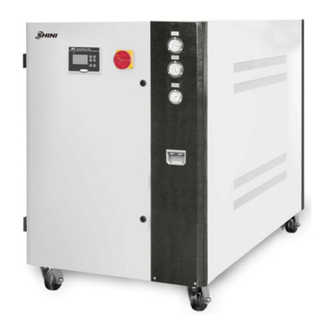
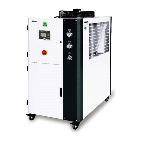
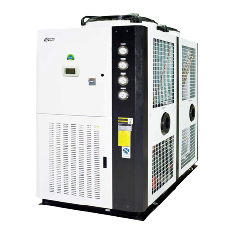
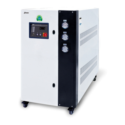
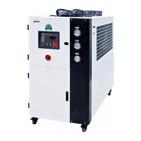
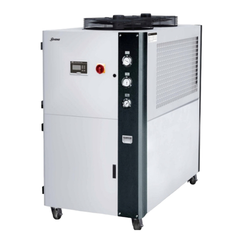
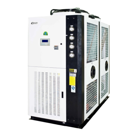
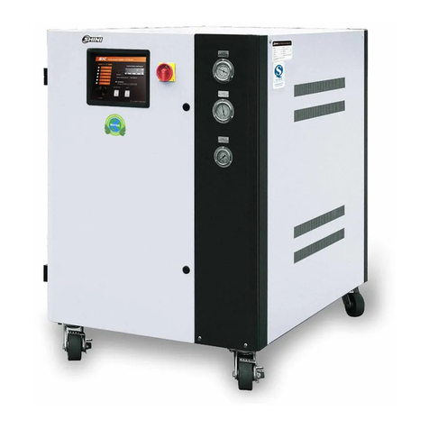
Shini SICC-W Series User manual

SICC-W Series
Water-cooledCentralWaterChiller
Date:Apr, 2013
Version: Ver.B(English)


3(53)
Contents
1. General Description..................................................................................7
1.1 CodingPrinciple...................................................................................8
1.2 Feature.................................................................................................8
1.3 TechnicalSpecifications.....................................................................10
1.3.1 SICC-WDimensions................................................................10
1.3.2 Specification............................................................................11
1.4 SafetyRegulations.............................................................................15
1.4.1 SafetySignsand Labels..........................................................15
1.4.2 Signsand Labels.....................................................................15
1.5 ExemptionClause..............................................................................15
2. StructureCharacteristics and WorkingPrinciple.................................17
2.1.1 WorkingPrincipleofSICC-WSingleUnit Series.....................17
2.1.2 WorkingPrincipleofSICC-WDoubleUnit Series....................18
2.2 AssemblyDrawing.............................................................................19
2.2.1 StructureDrawingof SICC-WSingleUnit................................19
2.2.2 StructureDrawingof SICC-WDoubleUnit..............................20
2.3 ElectricalDiagram..............................................................................21
2.3.1 SICC-WSingleSystem/ BitzerCompressor/ PartWindingStart
.................................................................................................21
2.3.2 SICC-WSingleSystem/ BitzerCompressor/ Star-deltaStart22
2.3.3 SICC-WDoubleSystem/BitzerCompressor/PartWindingStart
.................................................................................................23
2.3.4 SICC-WDoubleSystem/ BitzerCompressor/ Star-deltaStart24
3. Installation and Debugging.....................................................................25
3.1 Installation NoticeItems.....................................................................25
3.2 WaterPipeInstallation.......................................................................26
3.3 Select the InstallationSite..................................................................28
3.4 BearingBase......................................................................................29
3.5 TheOverheadHoisting oftheUnit.....................................................30
3.6 PowerConnection..............................................................................31

4(53)
4. Operation Guide......................................................................................32
4.1 TheGeneralIntroduction of OperationalInterface.............................32
4.1.1 FeaturesDemonstration..........................................................32
4.1.2 SafetyRequirement.................................................................34
4.2 Unit Running......................................................................................35
4.2.1 Start Interface..........................................................................35
4.2.2 MainRunningInterface............................................................36
4.2.3 Setupinterface........................................................................36
4.2.4 UserSetupInterface................................................................37
4.2.5 StatusInquiryInterface............................................................38
4.2.6 HistoryRecordInterface..........................................................39
4.2.7 OperationInstructionInterface................................................40
4.2.8 Fault InquiryInterface..............................................................41
4.3 UserSetup.........................................................................................41
4.3.1 User's parametersetup...........................................................41
4.3.2 WeeklyTimingSetup...............................................................42
4.3.3 TheOperationSetupoftheCompressor.................................42
4.3.4 TimeSetup..............................................................................42
4.3.5 ContrastSetup.........................................................................43
4.3.6 PictureSetup...........................................................................43
4.3.7 ModifytheUserSetupPassword.............................................43
4.3.8 TimingLogic............................................................................43
4.3.9 Maintenance............................................................................44
4.3.10 PasswordManage...................................................................44
5. Trouble-shooting.....................................................................................46
6. Maintenance and Repair.........................................................................48
6.1 MaintenanceLtems............................................................................49
6.2 MaintenanceSchedule.......................................................................52
6.2.1 About theMachine...................................................................52
6.2.2 Installation &Inspection...........................................................52
6.2.3 DailyChecking.........................................................................52
6.2.4 WeeklyCheck..........................................................................52
6.2.5 MonthlyCheck.........................................................................52
6.2.6 TrimonthlyChecking................................................................52

5(53)
6.2.7 Check Half-yearly....................................................................53
6.2.8 YearlyChecking.......................................................................53
6.2.9 3yearChecking.......................................................................53
TableIndex
Table1-1 Specification of SICC-WSingleCompressorR22..........................11
Table1-2 Specification of SICC-WSingleCompressorR134a......................12
Table1-3 Specification of SICC-WDoubleCompressorR22........................13
Table1-4 Specification of SICC-WDoubleCompressorR134a....................14
PictureIndex
Picture1-1 SICC-WDimensions(OneCompressor).....................................10
Picture1-2 SICC-WDimensions(TwoCompressors)....................................10
Picture2-1 WorkingPrincipleofSICC-WSingleUnit Series.........................17
Picture2-2 WorkingPrincipleofSICC-WDoubleUnit Series........................18
Picture2-3 StructureDrawingofSICC-WSingleUnit....................................19
Picture2-4 StructureDrawingofSICC-WDoubleUnit..................................20
Picture2-5 SICC-WSingleSystem/ BitzerCompressor/ PartWindingStart21
Picture2-6 SICC-WSingleSystem/ BitzerCompressor/ Star-deltaStart....22
Picture2-7 SICC-WDoubleSystem/BitzerCompressor/PartWindingStart
..........................................................................................................................23
Picture2-8 SICC-WDoubleSystem/BitzerCompressor/ Star-deltaStart...24
Picture3-1 CoolingWaterpipe Installation.....................................................27
Picture3-2 WaterpipeInstallationforthe WaterChillingSystem...................28
Picture3-3 SelecttheInstallationSite............................................................29
Picture3-4 BearingBase...............................................................................29
Picture3-5 The OverheadHoistingoftheUnit...............................................31
Picture4-1 The GeneralIntroductionof Operational......................................32
Picture4-2 StartInterface..............................................................................35
Picture4-3 Mainrunninginterface.................................................................36
Picture4-4 Setup Interface............................................................................37
Picture4-5 UserSetup Interface....................................................................37

6(53)
Picture4-6 StatusInquiryInterface................................................................38
Picture4-7 HourlyCurveWindow..................................................................39
Picture4-8 HistoryWindow............................................................................39
Picture4-9 HistoryRecordInterface..............................................................40
Picture4-10 OperationInstruction Interface...................................................40
Picture4-11 FaultInquiryInterface................................................................41
Picture4-12 TimeSetup................................................................................42
Picture4-13 ContrastSetup...........................................................................43

7(53)
1.General Description
Read thismanualcarefullybeforeoperationtopreventdamageofthe
machine orpersonalinjuries.
SICC-Wserieswaterapplicableforcoolingmouldstoreduceproductsmolding
cycle, alsotheyareavailableinthecoolingofequipmentsinordertomaintaina
normaltemperature. Besides,theyaresuitableforotherindustrieswiththeneed
ofcooling.
Model: SICC-668WS

8(53)
1.1CodingPrinciple
S
I
CC
-
xxxWx
-
xx
Refrigerant:
Nocode=R22 R3=R134a
FirstThree Codes:Refrigerating Ccapacity(kW)
FourthCode:W=Water Cooled
FifthCode:S=SingleCompressor D=DoubleCompressors
ShiniCentralWater Chillers
1.2Feature
●German-made twinscrewcompressorwithlongerservicelife.
●Steplesscompressoroutput capacityadjustingfunctionaredesigned to
savepower.
●Evaporatorand condenserbuilt strictlyaccordingtonationalstandards.
●Extendabilityofthecontrollermakesupgrade ofbothhardwareand software
mucheasier.
●"Watchdog"technologymakesmicroprocessorabletoautomatically
diagnoseandsolvetheproblems.
●512Kmemoryforprogramsand128K off-powerdatastorage.
●Basedonserialnumber, frequencyandtimesoffaults,thecausescanbe
analyzed viabothqueryand statistics functionstodo theimprovements.
●Abletomonitorthesettingofactualtemp.and displaytemp.trendinhours
ordaily.
●Remotecontrolfunction turnson/off themachineaccordingtopreset timer,
dailymaximumsettingofStart/stopisthere.
Monitor ScreenStepless Adjustment Function
OilPressure
CR1
CR2
CR3
ABCD
Slide
Valve
Air
Exhaust
CR4
Air
Suction

9(53)
All serviceworkshouldbe carried out byaperson withtechnicaltrainingor
correspondingprofessionalexperience.The manualcontainsinstructionsforboth
handlingand servicing.Chapter6, whichcontainsserviceinstructionsintendedfor
serviceengineers. Otherchapterscontaininstructionsforthedailyoperator.
Anymodificationsofthemachinemustbe approved bySHINI inordertoavoid
personalinjuryand damagetomachine.Weshall not beliableforanydamage
causedbyunauthorized changeof themachine.
Ourcompanyprovidesexcellent after-salesservice. Shouldyou haveanyproblem
duringusingthemachine,pleasecontactthecompanyorthelocalvendor.
HeadquarterandTaipeifactory
Tel:(886)226809119
ShiniPlastics Technologies(Dongguan), Inc
Tel:(86)769 81116600
ShiniPlastics TechnologiesIndiaPvt.Ltd.
Tel:(91)250 3021166

10(53)
1.3Technical Specifications
1.3.1SICC-WDimensions
Picture1-1 SICC-W Dimensions (OneCompressor)
Picture1-2 SICC-WDimensions (TwoCompressors)

11(53)
1.3.2Specification
Table1-1 Specification of SICC-WSingleCompressorR22
Note: 1) Parametertestcondition: chilled water flow0.172m3/(h.kW); chilled water outlettemperature7;
cooling waterinlet temperature30;coolingwater flow0.215m3/(h.kW)
2) The noiselevel istested at 1meter infront ofand 1.5meter abovethe machine.
3) Asperapplicationneeds,steplesscompressoroutput capacityadjusting functioncanbe optionally
available.
4) Pleaseinformthe specialrequirementstousbeforegiving anorder.
5) "S"standforsingle compressor.

12(53)
Table1-2 Specification of SICC-WSingleCompressorR134a
Note: 1) Parametertestcondition: chilled water flow0.172m3/(h.kW); chilled water outlettemperature7℃;
cooling waterinlet temperature30℃;coolingwater flow0.215m3/(h.kW).
2) The noiselevelistested at1meterin front of and1.5meter abovethemachine.
3) Asperapplicationneeds,steplesscompressoroutput capacityadjusting functioncanbe optionally
available.
4) Pleaseinformthe specialrequirementstousbeforegiving anorder.
5) "S"standforsingle compressor.

13(53)
Table1-3 Specification of SICC-WDoubleCompressorR22
Note: 1) Parametertestcondition: chilled water flow0.172m3/(h.kW);chilledwater outlet temperature7℃;
cooling waterinlet temperature30℃;coolingwater flow0.215m3/(h.kW).
2) The noiselevelistested at1meterin front of and1.5meter abovethemachine.
3) Asperapplicationneeds,steplesscompressoroutput capacityadjusting functioncanbe optionally
available.
4) Pleaseinformthe specialrequirementstousbeforegiving anorder.
5) "D"stand for doublecompressors.

14(53)
Table1-4 Specification of SICC-WDoubleCompressorR134a
Note:1)The refrigerantcapacityis testedunderconditionsthatprocesswaterinlettemp.isat12℃,process
water outlettemp. isat7℃,coolingwater inlet temp.isat 30℃andcooling water outlettemp. isat
35℃.
2) The noiselevelistested at1meterin front of and1.5meter abovethemachine.
3) Asperapplicationneeds,steplesscompressoroutput capacityadjusting functioncanbe optionally
available.
4) Pleaseinformthe specialrequirementstousbeforegiving anorder.
5) "D"stand for doublecompressors.

15(53)
1.4SafetyRegulations
Strictlyabide bythe followingsafetyregulationstoprevent damageofthe
machine orpersonalinjuries.
1.4.1SafetySignsand Labels
Theinstallationofelectricaldevicesshouldbe conductedbyprofessional
electricians.
Duringrepairing and maintenance, must turnoff themainswitchand
controlswitch.
Warning!
HighVoltagedanger!
Put upthissymbolinthe shell oftheelectriccabinet.
Warning!
Becareful!Thissymbolstandsthat takecarefulhereby!
Attention!
Noneed forregularinspectionbecauseall theelectricalpartsinthe
controlunit arefixed tightly!
1.4.2Signsand Labels
Highpressuregauge:displaypressurein
the high-pressuresideofrefrigerant
system.
Lowpressuregauge:displaypressurein
the low-pressuresideofrefrigerant
system.
1.5 Exemption Clause
Thefollowingstatementsclarifytheresponsibilitiesandregulationsbornbyany

16(53)
buyeroruserwho purchasesproductsandaccessoriesfromShini(including
employeesandagents).
Shiniisexempted fromliabilityforanycosts,fees,claimsandlossescausedby
reasonsbelow:
1. Anycarelessorman-madeinstallations,operation andmaintenancesupon
machineswithoutreferringtothe Manualpriortomachineusing.
2. Anyincidentsbeyondhumanreasonablecontrols, whichincludeman-made
viciousordeliberatedamagesorabnormalpower,and machine faultscaused
byirresistiblenaturaldisastersincludingfire,flood,stormand earthquake.
3. Anyoperationalactionsthatarenotauthorized byShiniuponmachine,
includingaddingorreplacingaccessories, dismantling,deliveringorrepairing.
4. Employingconsumablesoroil mediathatarenotappointed byShini.

17(53)
2. Structure Characteristics andWorkingPrinciple
2.1.1WorkingPrincipleofSICC-WSingleUnit Series
TheSICC-Wwater-cooled centralwaterchillerismainlymadeupoffour
componentswhicharecompressor, condenser, thermostaticexpansion valve
and evaporator. It usessinglestagevaporcompressionrefrigerationsystem,
and takestheadvantageofthemechanismoftransformation between gasand
liquidstatusforabsorbingand releasingheatbyusingof refrigerant toachieve
the effectiveness of refrigeration.
Picture2-1 Working PrincipleofSICC-WSingleUnit Series
Symbol
Name Quantity
Symbol
Name Quantity
CM Compressor 1 CV Checkvalve 1
CD Condenser 1 HV High pressurecheck valve
1
CH Evaporator 1 HG High pressuregauge 1
EX Expansionvalve 1 LG Lowpressuregauge 1
FP Fuse 1 HP High pressureswitch 1
AV Liquid anglevalve
1 LP Lowpressureswitch 1
DS Dryfilter 1 TH Thermostat 1
SG Sight-window 1 FU Antifreezeswitch 1

18(53)
2.1.2WorkingPrincipleofSICC-WDoubleUnit Series
TheSICC-Wwater-cooled centralwaterchillerismainlymadeupoffour
componentswhicharecompressor, condenser, thermostaticexpansion valve
and evaporator. It usessinglestagevaporcompressionrefrigerationsystem,
and takestheadvantageofthemechanismoftransformation between gasand
liquidstatusforabsorbingand releasingheatbyusingof refrigerant toachieve
the effectiveness of refrigeration.
Picture2-2 Working PrincipleofSICC-WDoubleUnit Series
Symbol
Name Quantity
Symbol
Name Quantity
CM Compressor 2 CV Checkvalve 2
CD Condenser 2 HV High pressurecheck valve
2
CH Evaporator 1 HG High pressuregauge 2
EX Expansionvalve 2 LG Lowpressuregauge 2
FP Fuse 2 HP High pressureswitch 2
AV Liquid anglevalve
2 LP Lowpressureswitch 2
DS Dryfilter 2 TH Thermostat 1

19(53)
2.2AssemblyDrawing
2.2.1StructureDrawingof SICC-WSingleUnit
Names ofParts
1. Compressor 2. PLCcontrolpanel3. Electricalcontrolbox
4. Nameplateofthe unit 5. Condenser6. Expansion valve
7. Evaporator 8. Coldwater inlet 9. Coldwater outlet
10. Cooling water inlet11. Cooling water outlet
Picture2-3 StructureDrawing ofSICC-WSingleUnit

20(53)
2.2.2StructureDrawingof SICC-WDoubleUnit
Names ofParts
1. Compressor 2. PLCcontrolpanel3. Nameplateofthe unit
4. Expansion valve 5. Electricalcontrolbox 6. Coldwater outlet
7. Coldwater inlet8. Coldwater outlet9. Coldwater inlet
10. Evaporator 11. Condenser
Picture2-4 StructureDrawing ofSICC-WDoubleUnit
This manual suits for next models
44
Table of contents
Other Shini Chiller manuals
Popular Chiller manuals by other brands

TecoPonic
TecoPonic HYDROPONIC HY 500 manual

Moffat
Moffat Friginox RR11A Specification sheet

Dunham-Bush
Dunham-Bush ACDX Installation, operation and maintenance instructions

MRC
MRC FIGR-100 operating manual

McQuay
McQuay MAC060D4 Installation, operation & maintenance manual

Liebert
Liebert Indoor/Outdoor Process Chiller PS036A Specification sheet