J&E Hall HBLT-A1 User manual

Section 4
Publication 9-86
Issue 1 : 10/22
Section 9 Publication 9-86
Issue 1 : 10/22 Page 1 of 10
HB Products HBLT-A1 Liquid Level Transmitters
Contents
1. About this Publication.................................................................................................... 2
1.1. Safety Warnings and Symbols.................................................................................................2
1.2. Units of Measurement..............................................................................................................2
1.3. Terminology .............................................................................................................................2
1.4. Additional Copies.....................................................................................................................2
2. Introduction ................................................................................................................... 3
3. Technical Data .............................................................................................................. 3
4. Operation ...................................................................................................................... 5
5. Installation ..................................................................................................................... 5
5.1. General ....................................................................................................................................5
5.2. Wiring.......................................................................................................................................6
6. Commissioning.............................................................................................................. 6
6.1. Selecting the Refrigerant .........................................................................................................7
6.2. Signal Damping........................................................................................................................7
6.3. Calibration................................................................................................................................8
6.3.1. Adjusting the Minimum and Maximum Calibration Points .................................................8
6.3.1.1. Minimum Calibration....................................................................................................8
6.3.1.2. Maximum Calibration...................................................................................................8
6.3.1.3. Minimum Calibration When the Minimum Liquid Level is Different From 4 mA ...........8
6.3.1.4. Maximum Calibration When the Maximum Liquid Level is Different From 20 mA .......9
6.4. Restore Factory Default Settings .............................................................................................9
6.5. LED Indication..........................................................................................................................9
7. Maintenance................................................................................................................ 10
8. Faults and Remedies .................................................................................................. 10
9. Spare Parts ................................................................................................................. 10
10. Safe Disposal, End-of-life (EOL)................................................................................. 10
List of Figures
Fig 1 Arrangement, Dimensions and Model Numbers............................................................................4
Fig 2 Installation .....................................................................................................................................5
Fig 3 Installation into Standpipe or Vessel..............................................................................................6
Fig 4 Wiring ............................................................................................................................................6
List of Tables
Table 1 Technical Data...........................................................................................................................3
Table 2 Refrigerant Settings...................................................................................................................7
Table 3 Faults and Remedies...............................................................................................................10
J & E Hall International©2022
All rights reserved. No part of this publication may be reproduced or transmitted in any form or by
any means, electronic or mechanical, including photocopying, recording or by any information
storage or retrieval system, without permission in writing from the copyright holder.
The copyright in this publication shall be and remain the sole property of J & E Hall International.

HB Products HBLT-A1 Liquid Level Transmitters
Publication 9-86 Section 9
Page 2 of 10 Issue 1 : 10/22
1. About this Publication
These instructions have been prepared according to the following
standards:
•BS EN ISO 11442: Technical product documentation.
Document management;
•BS EN ISO 12100: Safety of machinery - General principles
for design - Risk assessment and risk reduction;
•BS EN 62023: Structuring of technical information and
documentation;
•BS EN 82079-1: Preparation of instructions for use.
Structuring, content and presentation. General principles
and detailed requirements.
1.1. Safety Warnings and Symbols
The system of safety warnings and symbols is based on:
•BS EN ISO 7010: Graphical symbols. Safety colours and
safety signs. Registered safety signs;
•BS EN 82079-1: Preparation of instructions for use.
Structuring, content and presentation. General principles
and detailed requirements.
DANGER
This indicates a hazard with a high level of risk, which if
not avoided, will result in death or serious injury if
instructions, including recommended precautions, are
not followed.
WARNING
This indicates a hazard with a medium level of risk,
which if not avoided, will result in death or serious
injury if instructions, including recommended
precautions, are not followed. In addition, there is a
high risk of damage to the component, product or
process.
CAUTION
This indicates a hazard with a low level of risk, which if
not avoided, will result in minor or moderate injury if
instructions, including recommended precautions, are
not followed. In addition, there is a potential risk of
damage to the component, product or process.
NOTE: Draws attention to important additional
information.
1.2. Units of Measurement
Quantities are expressed in SI units or SI derived units; refer to J & E Hall
International Standard JEH-ES-02 Guide to the International System of
Units (SI).
1.3. Terminology
Terminology, abbreviations and acronyms are those currently in use
throughout the refrigeration and air conditioning industry; refer to J & E
Hall International Standard JEH-ES-01 Definition of Terms and Acronyms
Used in the Refrigeration Industry.
1.4. Additional Copies
Obtain additional copies of these instructions from J & E Hall
International; go to www.jehall.com.
HB Products HBLT-A1 Liquid Level Transmitters
Section 9 Publication 9-86
Issue 1 : 10/22 Page 3 of 10
2. Introduction
HBLT-A1 liquid level transmitters are used to measure refrigerant liquid
level for control applications. The transmitter supplies a 4 to 20 mA
signal in proportion to the level of liquid refrigerant. This signal can be
used with a suitable controller to measure and control the level of
refrigerant within a vessel.
The location of the liquid level transmitter and details of the level
controller can be found from the system schematic flow diagram and in
Part A : Specification in Section 1 of the plant instruction manual.
This publication covers HBLT-A1 level transmitters, for other types of HB
level transmitter refer to publication 9-85.
3. Technical Data
General
Type Rigid transmitter
Refrigerants R22, R134a, R404A, R507A,
R717 (ammonia), R718 (water), R744 (CO2)
Electrical
Voltage 24 V ac/dv + 10 % (50/60 Hz)
Power 1.5 W
Maximum load resistance 500 Ω (max)
Connection Plug 4 pins DIN 43650
Cable Wire Size 3 x 0.34 mm2
Analogue output 4 to 20 mA
Indication Red LEDs (bar graph)
Configuration Pushbutton
Environmental
Ambient
Temperatures
Transportation -40.0 to +70.0 °C
Operation -30.0 to +50.0 °C
Media temperature -60.0 to +80.0 °C
Pressure 100 bar (max)
Protection IP65
Vibration IEC 60068-2-6 (4g)
Mechanical
Available lengths 280 to 3000 mm and 6” to 120”
1Connection ¾” NPT or ¾” BSP
Material
Thread Stainless-steel AISI 303
Transmitter rod Stainless-steel AISI 304
Inner electrode PTFE coated
Transmitter housing Cast aluminium
Electronics Nylon 6 (PA)
Approvals
EMC - emission EN 61000-3-2
EMC - immunity EN 61000-4-2
GOST R No 0903044
Factory Default
Settings
Refrigerant R717 (ammonia)
Transmitter rod length 1500 mm (59”)
Signal damping 15 seconds
1Weld and thread adaptors are available, for example, ¾” NPT/1” BSP.
Table 1 Technical Data

HB Products HBLT-A1 Liquid Level Transmitters
Publication 9-86 Section 9
Page 4 of 10 Issue 1 : 10/22
BSP Threads
NPT Threads
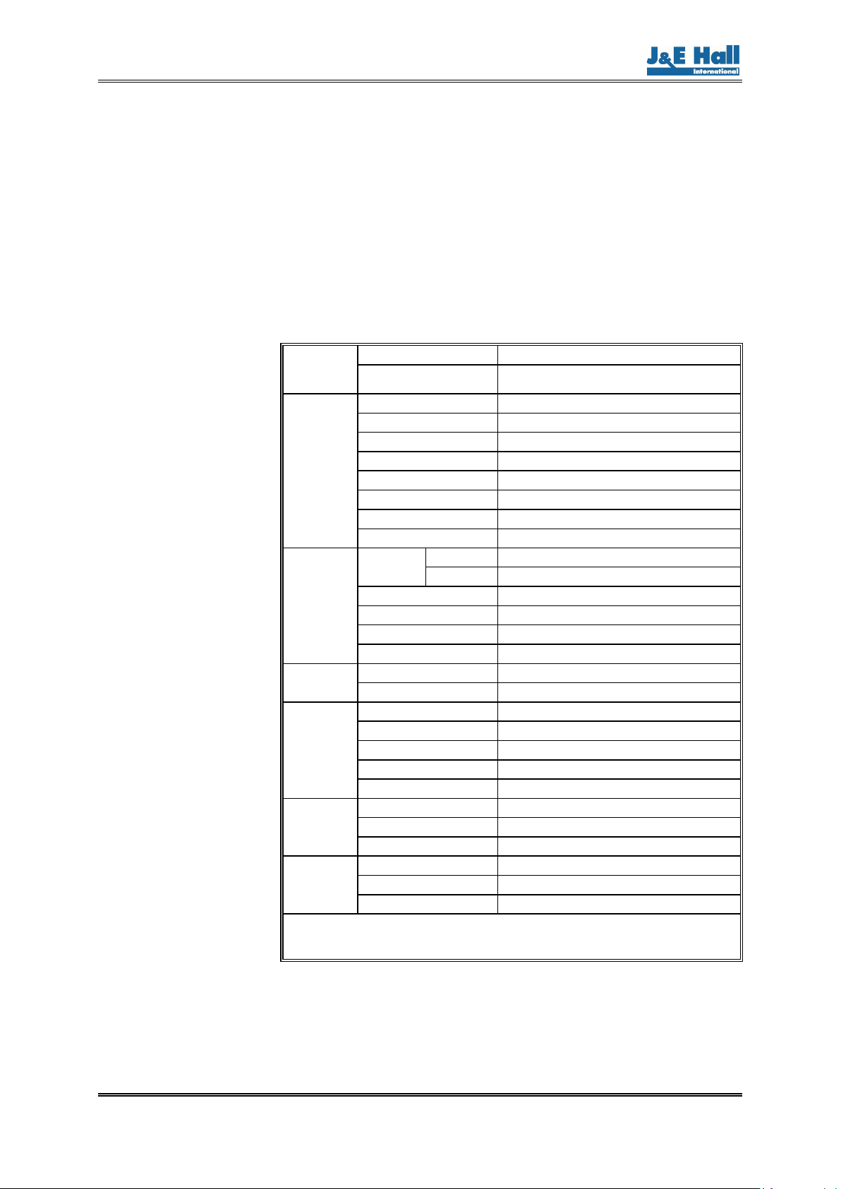
Item Description Item Description Item Description
1 Screw - cover 4 Calibration pushbutton 7 Spanner flats
2 DIN plug 5 Cover – transmitter housing 8 Threads (BSP or NPT)
3 Red LEDs (bar graph) 6 Transmitter housing 9 Transmitter rod
Level Transmitter Transmitter
Rod Length L
mm/in
Thread
Level Transmitter Transmitter
Rod Length L
mm/in
Thread
Without LED
Bar Graph
With LED
Bar Graph Without LED
Bar Graph
With LED
Bar Graph
HBLT-A1-2.8 HBLT-A1B-2.8 280 mm
1” BSP
HBLT-A1-15.3U HBLT-A1B-15.3U 15.3 in
¾ NPT
HBLT-A1-5 HBLT-A1B-5 500 mm HBLT-A1-19.2U HBLT-A1B-19.2U 19.2 in
HBLT-A1-8 HBLT-A1B-8 800 mm HBLT-A1-23.1U HBLT-A1B-23.1U 23.1 in
HBLT-A1-10 HBLT-A1B-10 1000 mm HBLT-A1-30U HBLT-A1B-30U 30 in
HBLT-A1-12 HBLT-A1B-12 1200 mm HBLT-A1-35Y HBLT-A1B-35Y 35 in
HBLT-A1-15 HBLT-A1B-15 1500 mm HBLT-A1-45U HBLT-A1B-45U 45 in
HBLT-A1-17 HBLT-A1B-17 1700 mm HBLT-A1-55U HBLT-A1B-55U 55 in
HBLT-A1-22 HBLT-A1B-22 2200 mm HBLT-A1-65U HBLT-A1B-65U 65 in
HBLT-A1-30 HBLT-A1B-30 3000 mm HBLT-A1-85U HBLT-A1B-85U 85 in
HBLT-A1-6U HBLT-A1B-6U 6 in
¾ NPT
HBLT-A1-105U HBLT-A1B-105U 105 in
HBLT-A1-8U HBLT-A1B-8U 8 in HBLT-A1-120U HBLT-A1B-120U 120 in
HBLT-A1-12U HBLT-A1B-12U 12 in
Fig 1 Arrangement, Dimensions and Model Numbers
1
3
5
2
4
6
7
8
9
HB Products HBLT-A1 Liquid Level Transmitters
Section 9 Publication 9-86
Issue 1 : 10/22 Page 5 of 10
4. Operation
Liquid level is detected by change in capacitance. The hollow transmitter
rod acts as one plate of the capacitor, the PTFE coated electrode inside
the rod acts as the other plate.
As the liquid level rises and falls there is a change in the value of
capacitance. The electronics inside the transmitter housing converts this
change to a 4 to 20 mA signal in proportion to the change in liquid level.
It is not necessary to break into the system to replace the transmitter
housing electronics. This item can be separated from the transmitter rod
by hand.
5. Installation
5.1. General
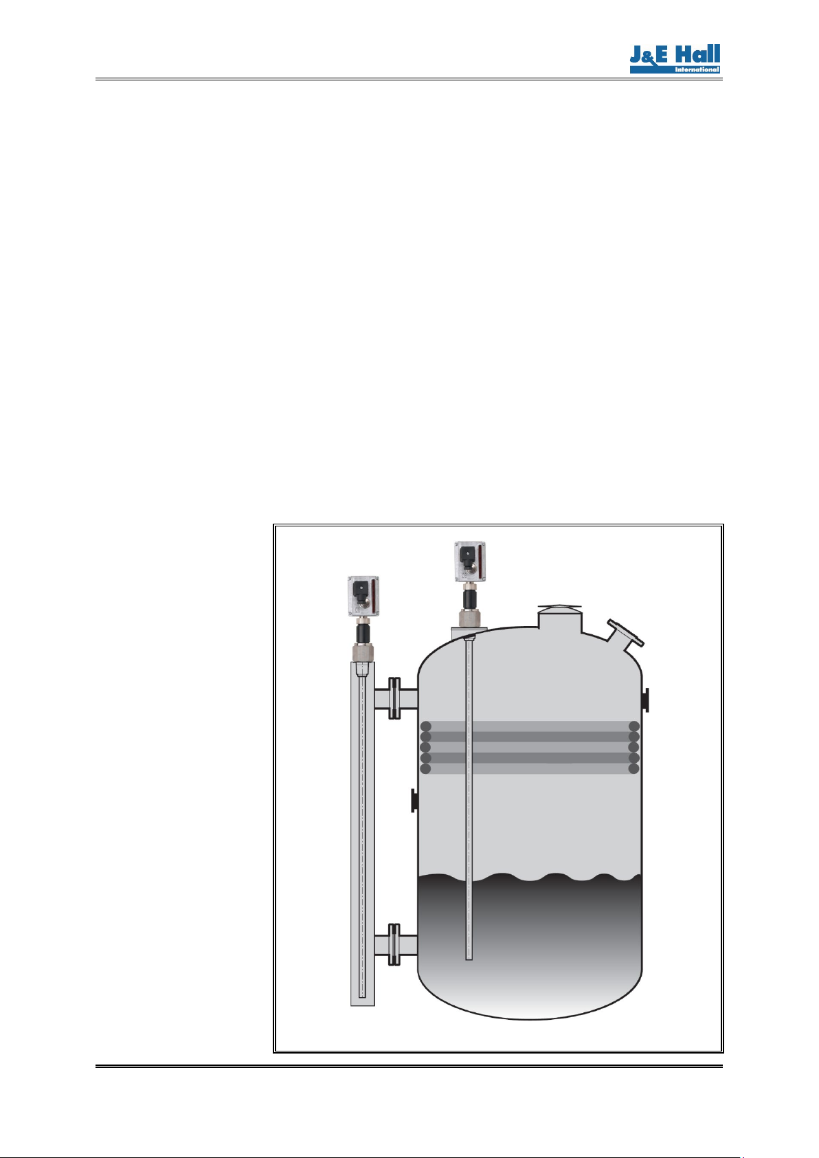
To minimise interference from turbulence installation in a standpipe is
recommended although direct installation into a vessel or tank is
possible; refer to Fig 2.
The level transmitter must be installed:
•In a vertical position;
•With a minimum clearance of 50 mm between the bottom of
the transmitter rod and the bottom of the standpipe, vessel
or tank;
•Allowing adequate space above for transmitter removal.
Install the transmitter as shown in Fig 3.
Fig 2 Installation

HB Products HBLT-A1 Liquid Level Transmitters
Publication 9-86 Section 9
Page 6 of 10 Issue 1 : 10/22
Fig 3 Installation into Standpipe or Vessel
5.2. Wiring
The transmitter supplies a 4 to 20 mA signal in proportion to the level of
liquid refrigerant to a suitable controller (PLC).
Refer to J & E Hall International certified wiring diagrams for electrical
connections specific to this application. Take particular care regarding
the termination of screened cable; refer to the notes on the wiring
diagrams
Fig 4 Wiring
6. Commissioning
WARNING
The pressure and temperature parameters detailed in
Table 1 must NOT be exceeded when pressure testing
the plant.
When the plant is charged with refrigerant for the first time, leave the
isolating stop valves in the open position. If the level column has been
isolated for maintenance while the vessel to which it is fitted is still under
system temperature and pressure, open the stop valve at the top of the
column first of all, then open the valve at the bottom by a small amount to
allow the column to slowly fill with liquid.
During commissioning, check the probe/level column joint for leaks.
Tighten to 80 to
150 Nm
NPT threads: use Loctite 577 thread sealer
BSP threads: use sealing ring provided
HB Products HBLT-A1 Liquid Level Transmitters
Section 9 Publication 9-86
Issue 1 : 10/22 Page 7 of 10
6.1. Selecting the Refrigerant
The liquid level transmitter is supplied factory set for use with R717
(ammonia) refrigerant. If this refrigerant is used there is no need to
change this setting. For other refrigerants, or if the transmitter housing
electronics have been replaced, proceeds as follows:
(a) Arrange to measure the 4 to 20 mA output signal.
(b) Disconnect the power supply by unplugging the DIN plug from the
transmitter housing.
(c) Press the calibration pushbutton and keep it pressed while
restoring the power supply (reinstate the DIN plug). Release the
pushbutton.
NOTE: If the power supply is restored before the
calibration pushbutton is pressed, the signal damping
will be changed; refer to 6.2.
(d) Observe the green LED flashing, at the same time measure the
4 to 20 mA output signal; refer to Table 2.
Green LED Number of Flashes 4 to 20 mA Output Signal 1Refrigerant
1 flash 5 mA R717 (ammonia) (factory setting)
2 flashes 6 mA R22 and R507A
3 flashes 7 mA R404A
4 flashes 8 mA R134a
5 flashes 9 mA R744 (CO2)
1For refrigerants not listed, contact J & E Hall International.
Table 2 Refrigerant Settings
(e) Press and release the pushbutton to step down through the list
until the number of LED flashes and the output signal correspond
to the required refrigerant.
When the output current corresponds to the required
refrigerant, wait 10 seconds until the green LED is constantly
lit (not flashing). This indicates that the required refrigerant
has been selected.
(f) Leave change of refrigerant mode by disconnecting the power
supply to the transmitter (unplug the DIN plug from the transmitter
housing).
(g) Reinstate the power supply.
6.2. Signal Damping
The signal damping setting range is 1 to 120 seconds, factory setting 15
seconds. To change the signal damping proceed as follows:
(a) Disconnect the power supply by unplugging the DIN plug from the
transmitter housing. Restore the power supply (reinstate the DIN
plug).
(b) Press and release the calibration pushbutton. Each press and
release increases the signal damping by 1 second from 1 second
up to a maximum of 120 seconds.
For example, to set signal damping to 37 seconds, press
and release the pushbutton 37 times.
(c) 10 seconds after the last press and release, the damping value is
saved to memory and the green LED will start flashing.
If the damping is set too high, repeat the procedure from
step (a).

HB Products HBLT-A1 Liquid Level Transmitters
Publication 9-86 Section 9
Page 8 of 10 Issue 1 : 10/22
6.3. Calibration
The level transmitter electronics are calibrated for R717 (ammonia)
refrigerant (refer to 6.1) and a transmitter rod length of 1500 mm (59”).
The default factory settings are:
•0 % (transmitter rod completely uncovered) output signal
4 mA;
•100 % (transmitter rod completely covered with liquid) output
signal is 20 mA.
Calibration is not required if the system refrigerant is R717 (ammonia)
and the transmitter rod length corresponds to the actual liquid measuring
range. However, calibration is necessary if:
•The level transmitter is used with a refrigerant other than
R717 (ammonia);
•A transmitter rod length other than 1500 mm (59”) is used in
which case the maximum and minimum calibration points
require adjustment;
•It is required to replace the transmitter housing electronics.
6.3.1. Adjusting the Minimum and Maximum Calibration Points
6.3.1.1. Minimum Calibration
(a) Lower the liquid level in the vessel to the desired minimum level.
(b) Press and hold the calibration pushbutton for approximately 5
seconds until the green LED stops flashing. Release the
pushbutton.
(c) Press and release the pushbutton once within the next 10 seconds.
NOTE: The level switch will return to normal operation if
the pushbutton is not pressed within 10 seconds.
After a few seconds the green LED starts to flash. The
output is now set to 4 mA and the level transmitter is in
normal operation.
6.3.1.2. Maximum Calibration
(a) Raise the liquid level in the vessel to the desired maximum level.
(b) Press and hold the calibration pushbutton for approximately 5
seconds until the green LED stops flashing. Release the
pushbutton.
(c) Within the next 10 seconds press and release the pushbutton twice
with a 1 second delay between each press.
NOTE: The level switch will return to normal operation if
the pushbutton is not pressed twice within 10 seconds.
After a few seconds the green LED starts to flash. The
output is now set to 20 mA and the level transmitter is in
normal operation.
6.3.1.3. Minimum Calibration When the Minimum Liquid Level is Different
From 4 mA
(a) Arrange to measure the 4 to 20 mA output signal.
(b) Lower the liquid level in the vessel to the desired minimum level.
(c) Press and hold the calibration pushbutton for approximately 5
seconds until the green LED stops flashing. Release the
pushbutton.
(d) Within the next 10 seconds, press the pushbutton and keep it
pressed.
NOTE: The level switch will return to normal operation if
the pushbutton is not pressed within 10 seconds.

HB Products HBLT-A1 Liquid Level Transmitters
Section 9 Publication 9-86
Issue 1 : 10/22 Page 9 of 10
(e) Starting at 4 mA, observe the output signal increasing. Release
the pushbutton when the output signal is approximately 0.5 mA
from the desired point.
(f) Repeat steps (c) and (d). Each repeat will increase the output
signal by approximately 0.05 mA.
10 seconds after the last repeat the green LED starts to
flash. The output now corresponds to the last measured
value and the level transmitter is in normal operation.
6.3.1.4. Maximum Calibration When the Maximum Liquid Level is Different
From 20 mA
(a) Arrange to measure the 4 to 20 mA output signal.
(b) Raise the liquid level in the vessel to the desired maximum level.
(c) Press and hold the calibration pushbutton for approximately 5
seconds until the green LED stops flashing. Release the
pushbutton.
(d) Within the next 10 seconds press and release the pushbutton then
after 1 second press again and keep the button pressed.
NOTE: The level switch will return to normal operation if
the pushbutton is not pressed twice within 10 seconds.
(e) Starting at 20 mA, observe the output signal decreasing. Release
the pushbutton when the output signal is approximately 0.5 mA
from the desired point.
(f) Repeat steps (c) and (d). Each repeat will decrease the output
signal by approximately 0.05 mA.
10 seconds after the last repeat the green LED starts to
flash. The output now corresponds to the last measured
value and the level transmitter is in normal operation.
6.4. Restore Factory Default Settings
Press and hold the calibration pushbutton for ≥20 seconds, until the
green LED starts flashing indicating that the factory reset is complete.
Release the pushbutton.
The default setting is for use with R717 (ammonia) refrigerant and a
transmitter rod length of 1500 mm (59”), change if required; refer to 7.1 to
7.4.
6.5. LED Indication
When power is applied to the level transmitter the LED will flash rapidly
as many times as the transmitter has been calibrated during its lifetime.
The 4 to 20 mA output signal is recognised and updated as soon as the
flashing changes from rapid to slow flashing.
Normal Operation
The green LED flashes slowly during normal operation. Generally, the
green LED is lit when the calibration pushbutton is pressed.
Selecting the Refrigerant
Refer to 6.1.
The green LED is unlit until the pushbutton is released at the end of step
(b). The LED then flashes a number of times according to the refrigerant,
then remains lit when the refrigerant has been selected.
Calibration
Refer to 6.3.
While calibration is taking place during step (b) the green LED is unlit.

HB Products HBLT-A1 Liquid Level Transmitters
Publication 9-86 Section 9
Page 10 of 10 Issue 1 : 10/22
7. Maintenance
No routine maintenance is required other than periodically checking that
the level indicated corresponds to the liquid level within the vessel.
If the system uses R717 (ammonia) refrigerant, oil may tend to collect at
the bottom of the level column. The HBLT-A1 is less susceptible to oil
logging than other designs of level transmitter, however, if it is suspected
that oil accumulation might be interfering with the correct operation of the
transmitter, drain off the oil using the apparatus and method illustrated
and described in Pumping Down, Recovering Ammonia Refrigerant
Charge in publication 5-20 in Section 5.
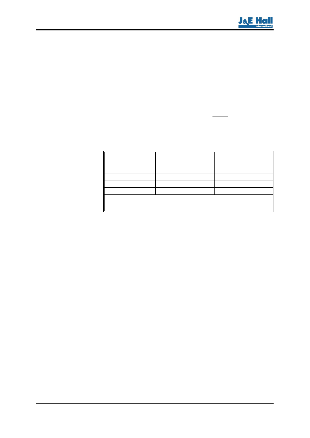
8. Faults and Remedies
Some of the more common fault conditions are given in Table 3.
Fault Probable Cause Remedy
No function, green LED not lit.
No power supply or power supply incorrect, faulty
wiring/plug.
Check power supply is available, supply polarity and
voltage is correct. Check wiring continuity and plug
connections.
Level transmitter electronic defective. Replace electronics.
No 4 to 20 mA output signal, green LED flashes
rapidly.
Faulty wiring/plug Check supply polarity. Check wiring continuity and
plug connections.
4 to 20 mA output signal does not correspond to the
actual liquid level
Wrong refrigerant selected. Select correct refrigerant; refer to 6.1.
Level transmitter not calibrated or incorrect
calibration.
Calibrate level transmitter; refer to 6.3. If calibration
has been carried out incorrectly, restore factory
default settings before recalibrating.
4 to 20 mA output signal is low or erratic Oil accumulation in the standpipe. Drain off the oil; refer to 7. Maintenance.
After supplying power to the level transmitter, there is
a long delay before the 4 to 20 mA output signal is
recognised and updated
Minimum/maximum calibration has been carried
out many times.
When power is applied to the level transmitter the
LED will flash rapidly as many times as the
transmitter has been calibrated during its lifetime.
The 4 to 20 mA output signal is recognised and
updated as soon as the flashing changes from rapid
to slow flashing.
Table 3 Faults and Remedies
9. Spare Parts
Obtain spare parts from the address below:
J & E Hall International Telephone: +44 (0) 1332-253400
Hansard Gate, Fax: +44 (0) 1332-371061
West Meadows, Email: spares@jehall.co.uk
Derby, Website: www.jehall.com
DE21 6JN
England
When ordering always quote the J & E Hall International contract number
and the component serial number (if available).
10. Safe Disposal, End-of-life (EOL)
At the end of the level transmitter's working life, it should not be classed
as domestic waste but be disposed of separately by a registered
recycling company according to local and currently valid legislation.
This manual suits for next models
46
Table of contents
Other J&E Hall Transmitter manuals

Popular Transmitter manuals by other brands

DLO
DLO TuneStik quick start guide

Siemens
Siemens Sitrans LU-180 operating instructions

Sentera Controls
Sentera Controls RSMF-2R Series Mounting and operating instructions

Shinko
Shinko SGB instruction manual

Pfeiffer Vacuum
Pfeiffer Vacuum CPT 100 operating instructions

Duon System
Duon System AUTROL Series Operation manual


