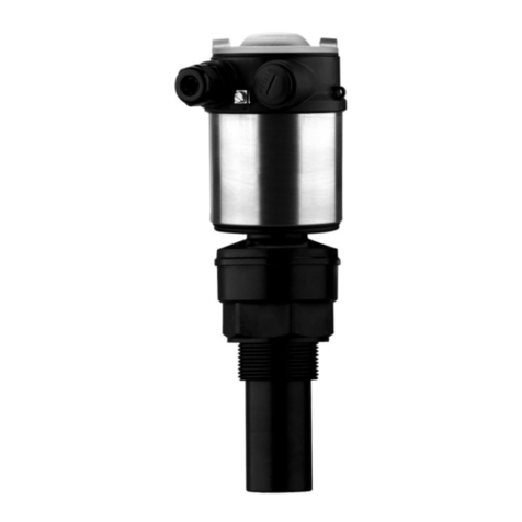
J&E Hall Danfoss AKS 41 User manual

Section 9
Publication 9-45
Issue 1 : 10/11
Section 9 Publication 9-45
Issue 1 : 10/11 Page 1 of 18
Danfoss AKS 41 Liquid Level Transmitter
Contents
1.
About this Publication ................................................................................................. 3
1.1.
Safety Warnings and Symbols................................................................................................3
1.2.
Units of Measurement.............................................................................................................3
1.3.
Terminology............................................................................................................................3
1.4.
Ordering Extra Copies ............................................................................................................3
2.
Application................................................................................................................... 4
3.
Operation .................................................................................................................... 4
4.
Technical Data ............................................................................................................ 5
5.
Installation ................................................................................................................... 6
6.
Adjustment .................................................................................................................. 8
6.1.
Setting for the Refrigerant.......................................................................................................8
6.2.
Calibration for Minimum and Maximum Liquid Level ..............................................................9
6.2.1.
Calibration for Minimum Liquid Level....................................................................................10
6.2.2.
Calibration for Maximum Liquid Level...................................................................................10
6.3.
Calibration for Minimum and Maximum Points Other Than 4 mA and 20 mA.......................10
6.3.1.
Minimum Calibration When Minimum Liquid Level Different From 4 mA ..............................10
6.3.2.
Maximum Calibration When Maximum Liquid Level Different From 20 mA ..........................11
6.4.
Signal Damping ....................................................................................................................11
6.5.
Restore Factory Default Settings ..........................................................................................12
7.
Commissioning.......................................................................................................... 12
8.
Maintenance.............................................................................................................. 12
9.
Faults and Remedies ................................................................................................ 13
10.
Spares....................................................................................................................... 14
11.
Appendix 1 AKS 41 Early Version ............................................................................ 15
11.1.
Measuring Test Voltage........................................................................................................15
12.
Adjustment (Early Version) ....................................................................................... 16
12.1.
Setting AKS 41 for the Refrigerant (Early Version)...............................................................16
12.2.
Calibration for Minimum Liquid Level (Early Version) ...........................................................16
12.3.
Calibration for Maximum Liquid Level (Early Version) ..........................................................16
12.4.
Calibration for Minimum and Maximum Points Other Than 4 mA and 20 mA.......................16
(Early Version)
12.5.
Signal Damping (Early Version)............................................................................................17
List of Figures
Fig 1 Principle of Operation ....................................................................................................................4
Fig 2 Wiring ............................................................................................................................................6
Fig 3 AKS 41 and AKS 41U Liquid Level Transmitters...........................................................................6
Fig 4 Calibration for the Refrigerant........................................................................................................8
Fig 5 Calibration for Minimum and Maximum Liquid Level .....................................................................9
Fig 6 4 to 20 mA Output Signal Damping .............................................................................................12
Fig 7 AKS 41 (Early Version) Internal Layout of Transmitter Housing and LED Function ....................15
List of Tables
Table 1 Technical Data...........................................................................................................................5
Table 2 Common Faults and Remedies ...............................................................................................14

Danfoss AKS 41 Liquid Level Transmitter
Publication 9-45 Section 9
Page 2 of 18 Issue 1 : 10/11
J & E Hall International
©
2011
All rights reserved. No part of this publication may be reproduced or transmitted in any form or by
any means, electronic or mechanical, including photocopying, recording or by any information
storage or retrieval system, without permission in writing from the copyright holder.
The copyright in this publication shall be and remain the sole property of J & E Hall International.

Danfoss AKS 41 Liquid Level Transmitter
Section 9 Publication 9-45
Issue 1 : 10/11 Page 3 of 18
1. About this Publication
These instructions have been prepared according to the following
standards:
BS 4884 : Technical Manuals:
Part 1 : 1992 Specification for Presentation of Essential
Information.
Part 2 : 1993 Guide to Content.
Part 3 : 1993 Guide to Presentation.
BS 4899 : User’s Requirements for Technical Manuals:
Part 1 : 1991 Content.
Part 2 : 1992 Presentation.
BS 4899 is based on the principles of BS 4884.
BS 5378 : Part 2 : 1982 Safety Signs.
1.1. Safety Warnings and Symbols
The system of safety warnings and symbols is based on BS 5378 :
Part 2 : 1982 Safety Signs and BS 4884 : Technical Manuals : Part 1 :
1992 Specification for Presentation of Essential Information.
WARNING
This denotes an immediate hazard with a high likelihood
of personal injury or death if instructions, including
recommended precautions, are not followed. There is
also a potential risk of damage to the product, process
or its surroundings.
CAUTION
This draws attention to instructions which must be
complied with to avoid damage to the product, process
or its surroundings.
NOTE: draws attention to important additional
information.
1.2. Units of Measurement
Quantities are expressed in SI units or SI derived units.
1.3. Terminology
Terminology, abbreviations and acronyms are those currently in use
throughout the refrigeration and air conditioning industry.
1.4. Ordering Extra Copies
Extra copies of these instructions can be obtained from J & E Hall
International. For contact details go to www.jehall.com.

Danfoss AKS 41 Liquid Level Transmitter
Publication 9-45 Section 9
Page 4 of 18 Issue 1 : 10/11
2. Application
AKS 41 and AKS 41U liquid level transmitters are used to measure
refrigerant liquid level for control applications. The transmitter supplies a
4 to 20 mA signal in proportion to the level of liquid refrigerant. This
signal can be used with a suitable controller to control the level of
refrigerant within a vessel. The Danfoss EKC 347 liquid level controller is
dedicated for use with the AKS 41 and AKS 41U.
The location of the liquid level transmitter and level controller can be
found from the system schematic flow diagram and in Part A :
Specification in Section 1 of the plant instruction manual.
This publication is applicable to the latest version of the AKS 41 and AKS
41U fitted with one green LED. Information about the earlier version,
fitted with one green and one red LED, can be found in Appendix 1.
3. Operation
The transmitter comprises consists of two parts: an inner insulated
electrode and an outer tube with a space between, forming a capacitive
rod. Liquid refrigerant flows up between the tube and the electrode; the
length immersed in the liquid is registered and transmitted as a 4 to
20 mA signal. The principle of operation is illustrated and described in
Fig 1.
In its simplest form, an electrical capacitor consists
of two conducting plates insulated from each other.
In this case the insulation medium is free-air.
When this example is translated to the capacitive
rod, the outer tube constitutes one plate and the
centre electrode the other plate.
Fig 1 Principle of Operation
Section through transmitter
(capacitive rod)
Electrode of
ordinary steel
Gap between the outer tube and
the insulated electrode where the
liquid can rise
Outer tube of stainless steel
Electrode hermetically
sealed in a non-conducting
PTFE material (Teflon)

Danfoss AKS 41 Liquid Level Transmitter
Section 9 Publication 9-45
Issue 1 : 10/11 Page 5 of 18
The capacitive rod can measure the level of conducting as well as non-
conducting liquids.
If the rod is partially immersed in a conducting liquid, for example, R717
(ammonia) or R718 (water).
On the part of the rod that is surrounded by liquid, the outer tube is
short-circuited to the teflon insulation. This produces an effect as if
the distance between the outer tube and the centre electrode has
become smaller which will cause an increase in the rod’s
capacitance. This change of capacitance is converted into an
output signal between 4 and 20 mA.
If the rod is partially immersed in a non-conducting liquid, for example,
R134a.
When the liquid rises between the outer tube and the inner
electrode, it displaces the gas otherwise present. As the liquid has
a higher dielectric constant than the gas, a rising liquid level is
registered as an increase in the rod’s capacitance and hence
results in a higher 4 to 20 mA output signal.
4. Technical Data
P
ARAMETER
D
ETAILS
General
Enclosure IP 65
Max working press 100 bar g
Temperature range -60 °C to +100 °C
Refrigerant R717 (factory setting), R22, R404a, R134a, R744 and R718 (R717 and
R718 give the same output signal)
Materials
Thread: stainless steel AISI 303
Reference tube: stainless steel AISI 304
Inner electrode: steel, PTFE coated
Top housing: cast aluminium
Environment
-25 to +55 °C during operation, -40 to +70 °C during transit.
20 to 80 % Rh (not condensed).
No shock influence or vibrations.
Approvals
EMC directive 89/336/EEC
EMC directive 92/31/EEC
EN 50081-1 and EN 50082-1
Electrical
Power supply 24 V ac -15 %/+25 % 50/60 Hz or 24 V dc ±10 %
Power consumption 1.5 W
Transmitter output 4 to 20 mA
Max load resistance 500 Ω
Connection 4-pole plug DIN 43650
Nomenclature
X X X X X X
Consecutive number
Serial number
Production year
Production month
Product type (code number)
Version number
The nomenclature code can be found inside the transmitter housing.
Table 1 Technical Data

Danfoss AKS 41 Liquid Level Transmitter
Publication 9-45 Section 9
Page 6 of 18 Issue 1 : 10/11
5. Installation
Allow adequate space for transmitter removal.
Locate a gasket seal under the hexagon portion of the transmitter body,
insert into the level column taking care not to bend the transmitter.
Tighten with a spanner on the hexagon flats provided.
Wiring connections to the probe are shown in Fig 2, also refer to the
control panel wiring diagrams specific to the application. Segregate
control wiring from power wiring, do not run together.
Fig 2 Wiring
AKS
41U AKS
41
M
ODEL
I
NSERTION
L
ENGTH
A W
EIGHT
M
ODEL
I
NSERTION
L
ENGTH
B W
EIGHT
AKS 41U-6 152 mm 1.32 kg AKS 41-3 280 mm 1.7 kg
AKS 41U-8 203 mm 1.41 kg AKS 41-5 500 mm 2.0 kg
AKS 41U-12 305 mm 1.55 kg AKS 41-8 800 mm 2.4 kg
AKS 41U-15.3 389 mm 1.72 kg AKS 41-10 1000 mm 2.7 kg
AKS 41U-19.2 488 mm 1.82 kg AKS 41-12 1200 mm 3.1 kg
AKS 41U-23.1 587 mm 1.96 kg AKS 41-15 1500 mm 3.5 kg
AKS 41U-30 762 mm 2.22 kg AKS 41-17 1700 mm 3.8 kg
AKS 41U-35 889 mm 2.38 kg AKS 41-22 2200 mm 4.6 kg
AKS 41U-45 1143 mm 2.71 kg AKS 41-30 3000 mm 5.8 kg
AKS 41U-55 1397 mm 3.1 kg
AKS 41U-65 1651 mm 3.5 kg
AKS 41U-85 2159 mm 4.3 kg
AKS 41U-105 2667 mm 4.93 kg
AKS 41U-120 3048 mm 5.7 kg
Fig 3 AKS 41 and AKS 41U Liquid Level Transmitters
EKC 347 Electronic
Liquid Level Controller
4 to 20 mA
Signal
24 V dc or
24 V ac 50/60 Hz
24 V ac
DIN Plug
Connection

Danfoss AKS 41 Liquid Level Transmitter
Section 9 Publication 9-45
Issue 1 : 10/11 Page 7 of 18
Fig 3 (continued) AKS 41 and AKS 41U Liquid Level Transmitters
Gasket Seal
Outer Tube
Plug can be
mounted in
four different
positions
Transmitter
housing and
tube can be
separated
without
emptying the
standpipe
A
B
1” BSP (AKS 41)
¾” NPT (AKS 41U)
Transmitter
Housing Assembly
DIN Plug
Connection
Calibration Cover
Green LED (‘flashes’ slowly
during normal operation)
LED Bar
Graph (option)
Inner Tube
Calibration
Cover
Calibration
Push-button

Danfoss AKS 41 Liquid Level Transmitter
Publication 9-45 Section 9
Page 8 of 18 Issue 1 : 10/11
6. Adjustment
6.1. Setting for the Refrigerant
The AKS 41/AKS 41U will not need setting if is used with R717
(ammonia) or R718 (water) and the length of the transmitter corresponds
to the actual refrigerant measured range.
For refrigerants R22, R404a, R134a and R744, set the AKS 41/AKS 41U
for the refrigerant as follows; refer to Fig 4. This procedure can be
carried out before the transmitter is mounted on the plant.
(a) Dismantle the cap on the DIN connecting plug and pull it back a
little on the cable to gain access to the four screw terminals inside
the plug where the four wires are connected. Connect a meter
between terminals 2 and 3 so that the 4 to 20 mA output signal can
be measured.
(b) Enter setting mode by removing the DIN plug so there is no voltage
to the level transmitter.
Press the calibration push-button and keep it depressed while
refitting the connecting plug. Release the push-button; the green
LED is extinguished until the push-button is released.
NOTE: this sequence must be observed. Restoring the
supply before the push-button is pressed will change
the signal damping.
(c) When the push-button is released, observe the green LED number
of flashes and the 4 to 20 mA output signal; refer to Fig 4.
(d) Press the calibration push-button to select the refrigerant. Each
press steps to the next refrigerant according to the table in Fig 4.
When the measured output current corresponds to the required
refrigerant, wait 10 seconds until the green LED is constant
illumination (not ‘flashing’). This indicates that the required
refrigerant has been selected.
G
REEN
LED
N
UMBER
O
FF
‘F
LASHES
’
O
UTPUT
S
IGNAL
R
EFRIGERANT
1 5 mA
1
R717 or R718
2 6 mA R22
3 7 mA R404a
4 8 mA R134a
5 9 mA R744
1
Default (factory setting)
Fig 4 Calibration for the Refrigerant
20 mA
4 mA
43 mm
30 mm

Danfoss AKS 41 Liquid Level Transmitter
Section 9 Publication 9-45
Issue 1 : 10/11 Page 9 of 18
(e) Remove the meter from the DIN plug and reassemble.
(f) Leave setting mode by removing the DIN plug so there is no
voltage to the level transmitter. After a few seconds, refit the plug.
The level transmitter should now operate normally.
(g) For refrigerants other than R717 and R718, it is recommended to
check the minimum and maximum liquid level calibration
approximately 7 days after operation commences; refer to 6.2.
6.2. Calibration for Minimum and Maximum Liquid Level
Calibrating the transmitter sets the two outer limits of the measuring
range, i.e. the point on the capacitance rod where the output signal is to
be 4 mA and the point where the signal is to be 20 mA; refer to Fig 5.
Fig 5 Calibration for Minimum and Maximum Liquid Level
The active measuring range starts 30 mm from the bottom of the rod and
ends 43 mm from the top (gasket’s contact face). The liquid level
transmitter has been factory-calibrated to R717 (ammonia), so that the
entire measuring range is utilised, i.e. the transmitter’s output signal is
4 mA when the rod is out of the liquid and 20 mA when the liquid is
43 mm from the top of the rod.
If the transmitter is to be used with R22, R404a, R134a or R744 there is
no need to calibrate, simply set to the refrigerant used; refer to 6.1.
It is usually necessary to calibrate the AKS 41/AKS 41U if:
•The AKS 41/AKS 41U is used with a refrigerant other than
those listed in Table 1.
•The insertion length does not correspond with the refrigerant
measured level range.
•The transmitter housing assembly is replaced.
Calibration for minimum liquid level can be carried out without calibrating
for maximum liquid level at the same time. However, if one level is
changed on its own the other level will automatically move by the same
distance. For example, if the new calibration for minimum liquid level is
10 mm further down the rod, the maximum liquid level moves down by
the same amount.
(mA) Output Signal

Danfoss AKS 41 Liquid Level Transmitter
Publication 9-45 Section 9
Page 10 of 18 Issue 1 : 10/11
6.2.1. Calibration for Minimum Liquid Level
(a) Bring the liquid refrigerant to the level corresponding to the lower
limit of the measuring range. i.e. the point on the rod where the
transmitter’s output signal is to be 4 mA. The full length of the rod
should be used if possible, so calibrate the lower limit with the
liquid level below the end of the rod.
(b) Press the calibration push-button and keep it depressed for
approximately 5 seconds, until the green LED stops ‘flashing’, then
release.
(c) Within the next 10 seconds, press the calibration push-button
once. After a few seconds the green LED illuminates begins to
‘flash’ slowly. The new minimum calibration has been saved to
memory.
NOTE: if the calibration push-button is not pressed
within 10 seconds, the AKS 41/AKS 41U will
automatically leave calibration mode and return to
normal operation.
The minimum output is now set to 4 mA and the AKS 41/AKS 41U
is operating normally.
6.2.2. Calibration for Maximum Liquid Level
(a) Bring the liquid refrigerant to the level corresponding to the
maximum limit of the measuring range. i.e. the point on the rod
where the transmitter’s output signal is to be 20 mA. The full
length of the rod should be used if possible, so calibrate the upper
limit with the liquid level 43 mm below the top of the rod (measured
from the gasket’s contact face).
(b) Press the calibration push-button and keep it depressed for
approximately 5 seconds, until the green LED stops ‘flashing’, then
release.
(c) Within the next 10 seconds, press the calibration push-button twice
with a 1 second interval between each press. After a few seconds
the green LED illuminates then begins to ‘flash’ slowly. The new
maximum calibration has been saved to memory.
NOTE: if the calibration push-button is not pressed
within 10 seconds, the AKS 41/AKS 41U will
automatically leave calibration mode and return to
normal operation.
The maximum output is now set to 20 mA and the AKS 41/AKS
41U is operating normally.
6.3. Calibration for Minimum and Maximum Points Other Than 4 mA and
20 mA
The usual minimum and maximum calibration points are 4 mA and
20 mA, however, the transmitter can be calibrated at other points within
the signal range. This facility is especially useful if it is impractical to
bring the liquid level to the maximum and minimum limits.
6.3.1. Minimum Calibration When Minimum Liquid Level Different From
4 mA
(a) Dismantle the cap on the DIN connecting plug and pull it back a
little on the cable to gain access to the four screw terminals inside
the plug where the four wires are connected. Connect a meter
between terminals 2 and 3 so that the 4 to 20 mA output signal can
be measured.
(b) Bring the refrigerant liquid level to the desired minimum level.
(c) Press the calibration push-button and keep it depressed for
approximately 5 seconds, until the green LED stops ‘flashing’, then
release.

Danfoss AKS 41 Liquid Level Transmitter
Section 9 Publication 9-45
Issue 1 : 10/11 Page 11 of 18
(d) Within the next 10 seconds, press the calibration push-button and
keep it pressed.
NOTE: if the calibration push-button is not pressed
within 10 seconds, the AKS 41/AKS 41U will
automatically leave calibration mode and return to
normal operation.
Observe the output mA signal increasing, starting at 4 mA.
Release the push-button when the output signal is approximately
0.5 mA away from the desired point. Pressing the button again
within 10 seconds will increase the output by 0.05 mA.
(e) Approximately 10 seconds after the last time the button was
pressed, the green LED illuminates then begins to ‘flash’ slowly.
The new minimum calibration has been saved to memory.
The minimum output now corresponds to the value measured the
last time the button was pressed and the AKS 41/AKS 41U is
operating normally.
(f) Remove the meter from the DIN plug and reassemble.
6.3.2. Maximum Calibration When Maximum Liquid Level Different From
20 mA
(a) Dismantle the cap on the DIN connecting plug and pull it back a
little on the cable to gain access to the four screw terminals inside
the plug where the four wires are connected. Connect a meter
between terminals 2 and 3 so that the 4 to 20 mA output signal can
be measured.
(b) Bring the refrigerant liquid level to the desired maximum level.
(c) Press the calibration push-button and keep it depressed for
approximately 5 seconds, until the green LED stops ‘flashing’, then
release.
(d) Within the next 10 seconds, press the calibration push-button and
keep it pressed.
NOTE: if the calibration push-button is not pressed
within 10 seconds, the AKS 41/AKS 41U will
automatically leave calibration mode and return to
normal operation.
Observe the output mA signal decreasing, starting at 20 mA.
Release the push-button when the output signal is approximately
0.5 mA away from the desired point. Pressing the button again
within 10 seconds will decrease the output by 0.05 mA.
(e) Approximately 10 seconds after the last time the button was
pressed, the green LED illuminates then begins to ‘flash’ slowly.
The new maximum calibration has been saved to memory.
The maximum output now corresponds to the value measured the
last time the button was pressed and the AKS 41/AKS 41U is
operating normally.
(f) Remove the meter from the DIN plug and reassemble.
6.4. Signal Damping
The liquid has an undefined surface that may produce an unstable level
signal. Damping of the 4 to 20 mA output signal is incorporated in the
level transmitter to reduce disturbances from this source to a minimum.
Signal damping is set as a reaction time that can be described as the
time it takes for the output signal to adjust to a new value after a sudden
change in liquid level; refer to Fig 6.

Danfoss AKS 41 Liquid Level Transmitter
Publication 9-45 Section 9
Page 12 of 18 Issue 1 : 10/11
Fig 6 4 to 20 mA Output Signal Damping
Signal damping is factory set at 15 seconds and can be altered within the
range 1 to 120 seconds. Setting the signal damping is performed while
the transmitter is operating.
(a) With the transmitter in operation, press the calibration push-button
once for each second by which you want to increase the damping.
Example:
1 press = 1 second
2 presses = 2 seconds
120 presses = 120 seconds
121 presses = 120 seconds
(b) After the first press the green LED stops ‘flashing’ and now only
illuminates when the button is pressed. 10 seconds after the last
press, the new signal damping value is saved in memory and the
green LED resumes ‘flashing’.
(c) If signal damping is set too high, repeat the procedure.
Each time damping is set, damping starts at 1 second. For
example, to increase the damping from 15 to 25 seconds, this
cannot be done with 10 presses of the button, it is necessary to
press the button 25 times.
6.5. Restore Factory Default Settings
To restore default settings, press the calibration push-button and keep it
depressed for a minimum of 20 seconds, until the green LED starts
‘flashing’. Release the push-button. When the LED starts flashing, reset
to factory default settings is completed.
7. Commissioning
WARNING
The pressure and temperature parameters detailed in
Table 1 must NOT be exceeded when pressure testing
the plant.
When the plant is charged with refrigerant for the first time, leave the
isolating stop valves in the open position. If the level column has been
isolated for maintenance while the vessel to which it is fitted is still under
system temperature and pressure, open the stop valve at the top of the
column first of all, then open the valve at the bottom by a small amount to
allow the column to slowly fill with liquid.
During commissioning, check the probe/level column joint for leaks.
8. Maintenance
No routine maintenance is required other than periodically checking that
the level indicated corresponds to the liquid level within the vessel. For
applications using R718 (water), if mineral deposits appear on the outside
of the transmitter tube, these should be removed.
4 to 20 mA
Output Signal
Liquid Level
Reaction Time

Danfoss AKS 41 Liquid Level Transmitter
Section 9 Publication 9-45
Issue 1 : 10/11 Page 13 of 18
If the system uses R717 (ammonia) refrigerant, oil may tend to collect at
the bottom of the level column and eventually interfere with the correct
operation of the transmitter. Check for oil logging and if necessary drain
off the oil using the apparatus and method illustrated and described in
Pumping Down, Recovering Ammonia Refrigerant Charge in publication
5-20 in Section 5.
9. Faults and Remedies
If the 4 to 20 mA output signal does not match the actual measured liquid
level, it is important to establish if the problem is due to the AKS 41/AKS
41U and not to the liquid level controller the 4 to 20 mA output signal is
connected to. Carry out the following checks:
Dismantle the cap on the DIN connecting plug and pull it back a little on
the cable to gain access to the four screw terminals inside the plug where
the four wires are connected.
Measure the resistance in the outer current loop between terminals 2 and
3 (the plug must not be mounted on the transmitter when carrying out this
check). If the resistance exceeds 500 Ω, check for disconnections or
excessive resistance in the level controller connected to the liquid level
transmitter.
Refit the inner part of the DIN plug to reconnect the level transmitter to
the level controller. Measure the supply voltage on the plug’s screw
terminals marked 1 and earth. Check that the voltage is between 20 and
30 V ac (18 and 48 V dc). If not ok, look for the cause in the transformer
and its connections.
Disconnect the wires from plug terminals 2 and 3 so that any errors in
wires or external equipment will not interfere with the measurement of
signal current. Measure the signal current directly between plug
terminals 2 and 3. If the measured current does not correspond to the
observed liquid level, proceed to the 5 fault descriptions in Table 2.

Danfoss AKS 41 Liquid Level Transmitter
Publication 9-45 Section 9
Page 14 of 18 Issue 1 : 10/11
1. FAULT: An output signal between 4 to 20 mA is measured but the current does not match the actual liquid level
Probable Cause Remedy
Level transmitter not set to the correct refrigerant. Set the transmitter to the refrigerant; refer to 6.
If the level transmitter is mounted in a standpipe, there may
reasons not directly connected to the transmitter/level
controller why the liquid level in the standpipe is not the
same as that in the vessel containing the refrigerant.
Check that stop valves connecting the standpipe to the
vessel are fully open. For applications using R717, check for
oil logging in the standpipe; refer to 8.
Level transmitter incorrectly calibrated. Recalibrate the level transmitter. Calibrate the lower limit
first (refer to 6.2.1) then see if whether the transmitter
measures correctly.
2. FAULT: Output signal current is 0 mA
Probable Cause Remedy
If the preliminary checks have been carried out correctly and
an output signal still cannot be measured, the level
transmitter is defective.
Fit a new liquid level transmitter.
3. FAULT: Output signal current is 2 mA (red LED is illuminated – early versions)
Probable Cause Remedy
The transmitter is measuring a liquid level lower than the
point calibrated as the minimum level (4 mA point). This can
happen if the rod is periodically completely out of the liquid.
Recalibrate the 4 mA point while the transmitter is out of the
liquid.
4. FAULT: Output signal current is constant 4 mA
Probable Cause Remedy
Green LED ‘flashing’ (red LED also ‘flashing’ – early
versions). The transmitter is in setting mode.
Interrupt the supply voltage for about 10 seconds to restore
the transmitter to normal operation.
Green LED extinguished (red LED ‘flashing’ – early
versions). The transmitter is in calibration mode.
Early versions only – remove the shorting strap from across
the two pins and store by placing over one of the two pins.
Green LED ‘flashing’ (red LED also extinguished – early
versions). The transmitter is operating normally and
registers that the liquid level is below the lower end of the
rod.
Check that the liquid level is able to rise (valve closed, oil
logging etc).
5. FAULT: Output signal current is 22 mA (red LED is illuminated – early versions)
Probable Cause Remedy
The transmitter is measuring a liquid level higher than the
point calibrated as the maximum level (20 mA point).
Check if the liquid level is abnormally high, i.e. beyond the
transmitter’s normal measuring range. Check that the
transmitter is set to the correct refrigerant. If the error is not
found here, recalibrate the transmitter.
Table 2 Common Faults and Remedies
10. Spares
In the event of a fault, if the problem is traced to the AKS 41/AKS 41U
itself rather than faulty wiring, liquid level controller etc, the only option is
to replace the liquid level transmitter.
Obtain a new AKS 41/AKS 41U from the address below, quote the
nomenclature code that can be found inside the transmitter housing:
J & E Hall International Telephone: +44 (0) 1332-253400
Hansard Gate, Fax: +44 (0) 1332-371061
Derby, Website: www.jehall.co.uk
DE21 6JN
England

Danfoss AKS 41 Liquid Level Transmitter
Section 9 Publication 9-45
Issue 1 : 10/11 Page 15 of 18
11. Appendix 1 AKS 41 Early Version
The early version of the AKS 41 is provided with two LEDs: one green,
one red. Pins are provided for measuring the 4 to 20 mA output signal
and for measuring a test voltage used for troubleshooting. Also, the
method of setting and calibration differs somewhat from the latter version.
G
REEN
LED R
ED
LED F
UNCTION
S
TATUS
O
UTPUT
S
IGNAL
4
TO
20
M
A
‘Flashing’ Off Normal operation Depends on liquid level
1
See note
‘Flashing’ Setting refrigerant 4, 5, 6, 7 or 8 mA (depends on
refrigerant selected)
Off Setting signal damping Depends on liquid level
Off ‘Flashing’ Calibrating output signal 4 to 20 mA in 2 mA steps
‘Flashing’ On Level more than 10 %
outside measured range
4 mA if below measured range
20 mA if above measured range
1
As long as the programming button is not activated, the green LED ‘flashes’. When the programming button is activated,
the green LED follows the activation, i.e. the green LED is On whenever the programming button is pressed.
Fig 7 AKS 41 (Early Version) Internal Layout of Transmitter Housing and LED Function
11.1. Measuring Test Voltage
Connect a voltmeter to the pins provided to measure a voltage which is
an expression of the ‘raw’ output signal measured directly from the
capacitive rod.
Two voltages are recorded during manufacture and recorded inside the
transmitter housing.
Voltage (x) at 0 %, i.e. when the rod is completely out of the liquid.
Voltage (y) at 100 %, i.e. when the rod is completely immersed in
the liquid.
In a trouble-shooting situation, by measuring the voltage between the
pins it is possible to determine whether the rod is defective. If the
measured voltage is within the two recorded values, the capacitive rod
(outer tube, insulation, electrode and wiring connections) are in order.
Green
LED
Red
LED
Two pins for
calibration of 4 to
20 mA signal
Programming
button (at
bottom of tube)
Two pins for measuring test voltage

Danfoss AKS 41 Liquid Level Transmitter
Publication 9-45 Section 9
Page 16 of 18 Issue 1 : 10/11
12. Adjustment (Early Version)
12.1. Setting AKS 41 for the Refrigerant (Early Version)
Same as the later version of the AKS 41; refer to 6.1. The red LED
‘flashes’ when the transmitter is in setting mode.
12.2. Calibration for Minimum Liquid Level (Early Version)
(a) There is a shorting strap provided at one of the two pins provided
for calibration of 4 to 20 mA output signal. Place this strap across
the two pins so they are short-circuited. The liquid level transmitter
is now in calibration mode: green LED extinguished, red LED
‘flashing’.
(b) Bring the liquid refrigerant to the level corresponding to the lower
limit of the measuring range, i.e. the point on the rod where the
transmitter’s output signal is to be 4 mA. The full length of the rod
should be used if possible, so calibrate the lower limit with the
liquid level below the end of the rod.
(c) Press the calibration push-button then release within 3 seconds.
The green LED will illuminate when the button is pressed.
Wait 10 seconds. The new minimum calibration has been saved to
memory.
(d) Unless the calibration of the maximum liquid level is to be carried
out, remove the shorting strap from across the two pins and store
by placing over one of the two pins.
12.3. Calibration for Maximum Liquid Level (Early Version)
(a) Normally, maximum calibration is done after minimum. If this is not
the case, carry out 12.2 step (a) first.
(b) Bring the liquid refrigerant to the level corresponding to the
maximum limit of the measuring range. i.e. the point on the rod
where the transmitter’s output signal is to be 20 mA. The full
length of the rod should be used if possible, so calibrate the upper
limit with the liquid level 45 mm below the top of the rod (measured
from the top gasket’s contact face).
(c) Press the calibration push-button then release within 3 seconds.
The green LED will illuminate when the button is pressed.
Wait 10 seconds. The new maximum calibration has been saved
to memory.
(d) Remove the shorting strap from across the two pins and store by
placing over one of the two pins.
12.4. Calibration for Minimum and Maximum Points Other Than 4 mA and
20 mA (Early Version)
The usual minimum and maximum calibration points are 4 mA and
20 mA, however, the transmitter can be calibrated at other points within
the signal range. This facility is especially useful if it is impractical to
bring the liquid level to the maximum and minimum limits.
It is necessary to measure the 4 to 20 mA output signal. Dismantle the
cap on the DIN connecting plug and pull it back a little on the cable to
gain access to the four screw terminals inside the plug where the four
wires are connected. Connect a meter between terminals 2 and 3 so that
the 4 to 20 mA output signal can be measured.
There is a shorting strap provided at one of the two pins for calibration of
4 to 20 mA output signal. Place this strap across the two pins so they are
short-circuited. The liquid level transmitter is now in calibration mode:
green LED extinguished, red LED ‘flashing’.

Danfoss AKS 41 Liquid Level Transmitter
Section 9 Publication 9-45
Issue 1 : 10/11 Page 17 of 18
When the programming push-button is pressed, .the 4 to 20 mA signal
increases in 2 mA steps, where each step is maintained for 4 seconds. If
the programming button is released at a certain step, the actual liquid
level is calibrated to the value the current has reached.
Release the programming button when the current has reached 4, 6, 8 or
10 mA to calibrate for minimum liquid level, wait until the current has
reached 12, 14, 16, 18 or 20 mA to calibrate for maximum liquid level.
Example:
AKS 41-12, insertion length 1200 mm
Lowest attainable liquid level = 100 mm measured from the end of
the rod.
Highest attainable liquid level = 950 mm measured from the end of
the rod.
A change in liquid level over the whole insertion length of 1200 mm will
give a change in the output signal of 20 mA – 4 mA = 16 mA
(disregarding the lowermost 35 mm of the rod and the uppermost 45 mm
which do not count). Therefore, a 1 mA change in signal current
corresponds to a change in liquid level of 1200/16 = 75 mm.
A signal current of 6 mA therefore corresponds to a liquid level of 2 x 75
= 150 mm and a signal current of 12 x 75 = 900 mm. As the liquid level
can be adjusted between 100 and 950 mm, it is possible to calibrate the
liquid level transmitter at the 6 mA minimum point and the 16 mA
maximum point.
(a) Measure the 4 to 20 mA signal and use the shorting strap as
already described.
(b) Bring the liquid level to its lowest point, 50 mm above the end of
the rod.
(c) Press the programming button and keep it pressed. When the
output signal reaches 6 mA, release the button.
(d) Wait 10 seconds until the signal has adjusted itself to 4 mA, the
minimum calibration point has now been saved to memory.
(e) Bring the liquid level to its highest point, 900 mm above the end of
the rod.
(f) Press the programming button and keep it pressed. When the
output signal reaches 16 mA, release the button.
(g) Wait 10 seconds until the signal has adjusted itself to 4 mA, the
maximum calibration point has now been saved to memory.
(h) After calibration is complete, remove the meter from the DIN plug
and reassemble. Remove the shorting strap from across the two
pins and store by placing over one of the two pins.
12.5. Signal Damping (Early Version)
Same as the later version of the AKS 41; refer to 6.4.

Danfoss AKS 41 Liquid Level Transmitter
Publication 9-45 Section 9
Page 18 of 18 Issue 1 : 10/11
This page intentionally bla
nk
Table of contents
Other J&E Hall Transmitter manuals
