Shinko SGB User manual

1
RATIO TRANSMITTER
SGB
SGBW
SGBL
INSTRUCTION MANUAL

2
Preface
Thank you for purchasing our SGB, SGBW or SGBL, Ratio Transmitter. This manual
contains instructions for the mounting, functions, operations and notes when operating the
SGB, SGBW or SGBL. To prevent accidents arising from the misuse of this instrument,
please ensure the operator receives this manual.
Notes
• This instrument should be used in accordance with the specifications described in the manual.
If it is not used according to the specifications, it may malfunction or cause a fire.
• Be sure to follow the warnings, cautions and notices. If they are not observed, serious
injury or malfunction may occur.
• The contents of this instruction manual are subject to change without notice.
• Care has been taken to ensure that the contents of this instruction manual are correct, but if
there are any doubts, mistakes or questions, please inform our sales department.
• This instrument is designed to be installed on a DIN rail within a control panel. If it is not,
measures must be taken to ensure that the operator does not touch power terminals or other
high voltage sections.
• Any unauthorized transfer or copying of this document, in part or in whole, is prohibited.
• Shinko Technos CO., LTD. is not liable for any damage or secondary damage(s) incurred as a
result of using this product, including any indirect damage.
SAFETY PRECAUTIONS (Be sure to read these precautions before using our products.)
The safety precautions are classified into categories: “Warning” and “Caution”.
Depending on circumstances, procedures indicated by Caution may result in serious
consequences, so be sure to follow the directions for usage.
Warning
Warning
• To prevent an electrical shock or fire, only Shinko or qualified service personnel may
handle the inner assembly.
• To prevent an electrical shock, fire, or damage to instrument, parts replacement may
only be undertaken by Shinko or qualified service personnel.
Safety Precautions
• To ensure safe and correct use, thoroughly read and understand this manual before
using this instrument.
•
This instrument is intended to be used for industrial machinery, machine tools and measuring
equipment. Verify correct usage after purpose-of-use consultation with our agency or main
office. (Never use this instrument for medical purposes with which human lives are involved.)
• External protection devices such as protection equipment against excessive temperature
rise, etc. must be installed, as malfunction of this product could result in serious damage
to the system or injury to personnel. Proper periodic maintenance is also required.
•
This instrument must be used under the conditions and environment described in this manual.
Shinko Technos Co., Ltd. does not accept liability for any injury, loss of life or damage occurring
d
ue to the instrument being used under conditions not otherwise stated in this manual.
Caution with Respect to Export Trade Control Ordinance
To avoid this instrument from being used as a component in, or as being utilized in the
manufacture of weapons of mass destruction (i.e. military applications, military
equipment, etc.), please investigate the end users and the final use of this instrument.
In the case of resale, ensure that this instrument is
not illegally exported.
Caution
Procedures which may lead to dangerous conditions and
cause death or serious injury, if not carried out properly.
Procedures which may lead to dangerous conditions and cause
superficial to medium injury or physical damage or may degrade
or damage the product, if not carried out properly.

3
Installation Precautions
Caution
This instrument is intended to be used under the following environmental conditions
(IEC61010-1): Overvoltage category , Pollution degree 2
Ensure the mounting location corresponds to the following conditions:
• A minimum of dust, and an absence of corrosive gases
• No flammable, explosive gases
• No mechanical vibrations or shocks
• No exposure to direct sunlight, an ambient temperature of -10 to 55 (14 to 131 )
that does not change rapidly, and no icing
• An ambient non-condensing humidity of 35 to 85 %RH
•
No large capacity electromagnetic switches or cables through which large current is flowing
• No water, oil or chemicals or the vapors of these substances can come into direct
contact with the unit.
• When installing this unit within a control panel, please note that ambient temperature of
this unit – not the ambient temperature of the control panel – must not exceed 55
(131 ). Otherwise the life of electronic components (especially electrolytic capacitor)
may be shortened.
Note: Avoid setting this instrument directly on or near flammable material even though
the case of this instrument is made of flame-resistant resin.
Wiring Precautions
Caution
• Do not leave bits of wire in the instrument, because they could cause a fire and
malfunction.
• When wiring, use a crimping pliers and a solderless terminal with an insulation sleeve
in which an M3 screw fits.
• Tighten the terminal screw using the specified torque. If excessive force is applied to
the screw when tightening, the screw or case may be damaged.
• This instrument does not have a built-in power switch, circuit breaker and fuse. It is
necessary to install a power switch, circuit breaker and fuse near the instrument.
(Recommended fuse: Time-lag fuse, rated voltage 250 V AC, rated current 2 A)
•
For wiring of the AC power source, be sure to use terminals as described in this manual.
If the AC power source is connected to incorrect terminals, the unit will be burnt out.
• Do not apply a commercial power source to the sensor which is connected to the
input terminal nor allow the power source to come into contact with the sensor.
• When using DC voltage and current input, do not confuse polarity when wiring.
• Keep the input/output wires and power line separate.
Operation and Maintenance Precautions
Caution
• Do not touch live terminals. This may cause an electrical shock or problems in operation.
• Turn the power supply to the instrument OFF when retightening the terminal or cleaning.
Working on or touching the terminal with the power switched ON may result in severe
injury or death due to electrical shock.
• Use a soft, dry cloth when cleaning the instrument.
(Alcohol based substances may tarnish or deface the unit.)
• As the display section is vulnerable, be careful not to put pressure on, scratch or strike
it with a hard object.

4
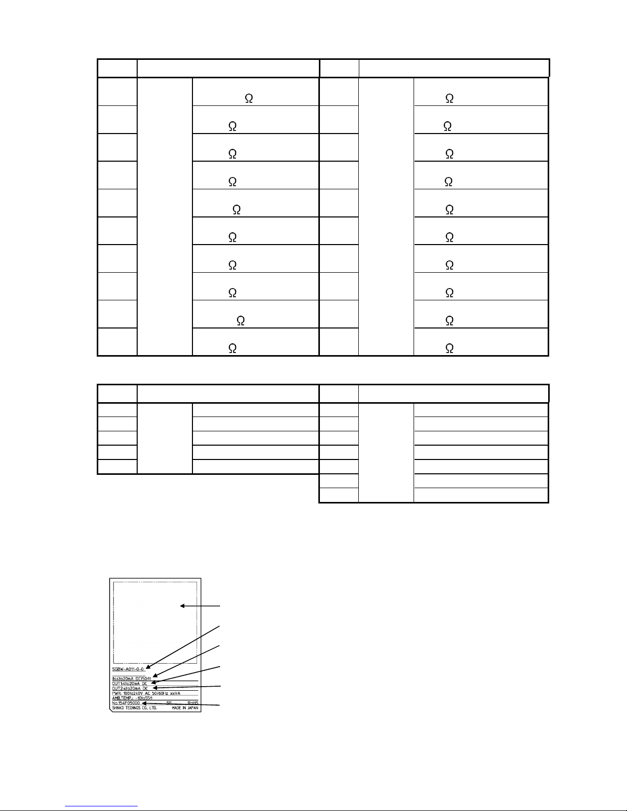
Characters used in this manual [: No character is indicated (unlit).]
Indication
Number, / -1 0 1 2 3 4 5 6 7 8 9 °C °F
Indication
Alphabet A B C D E F G H I J K L M
Indication
Alphabet N O P Q R S T U V W X Y Z
Contents Page
1. Model ....................................................................................................................................5
1.1 Model..........................................................................................................................5
1.2 How to Read the Model Label .................................................................................6
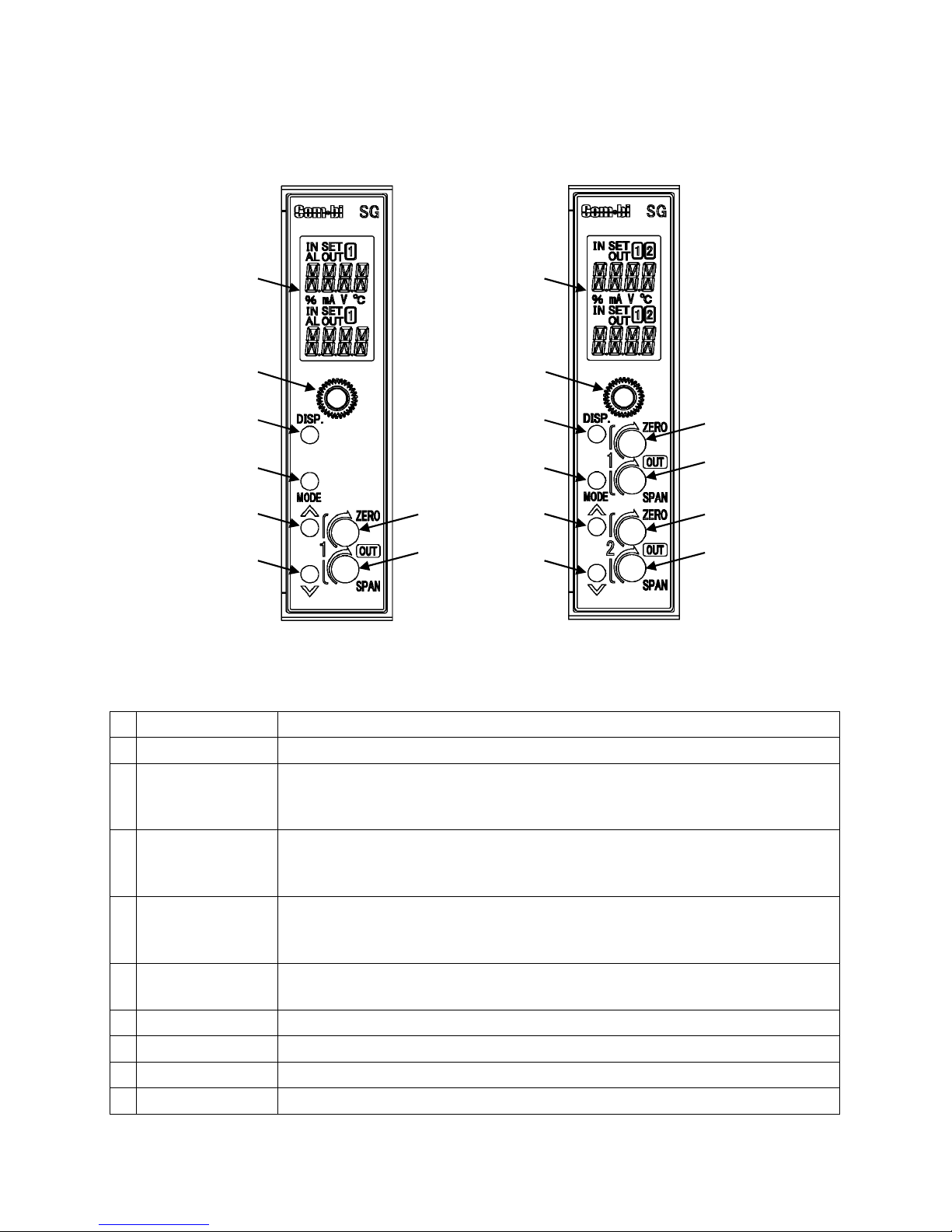
2. Name and Functions...........................................................................................................7
2.1 Front Panel ................................................................................................................7
2.2 Display Section .........................................................................................................8
3. Mounting ..............................................................................................................................9
3.1 External Dimensions (Scale: mm) ..........................................................................9
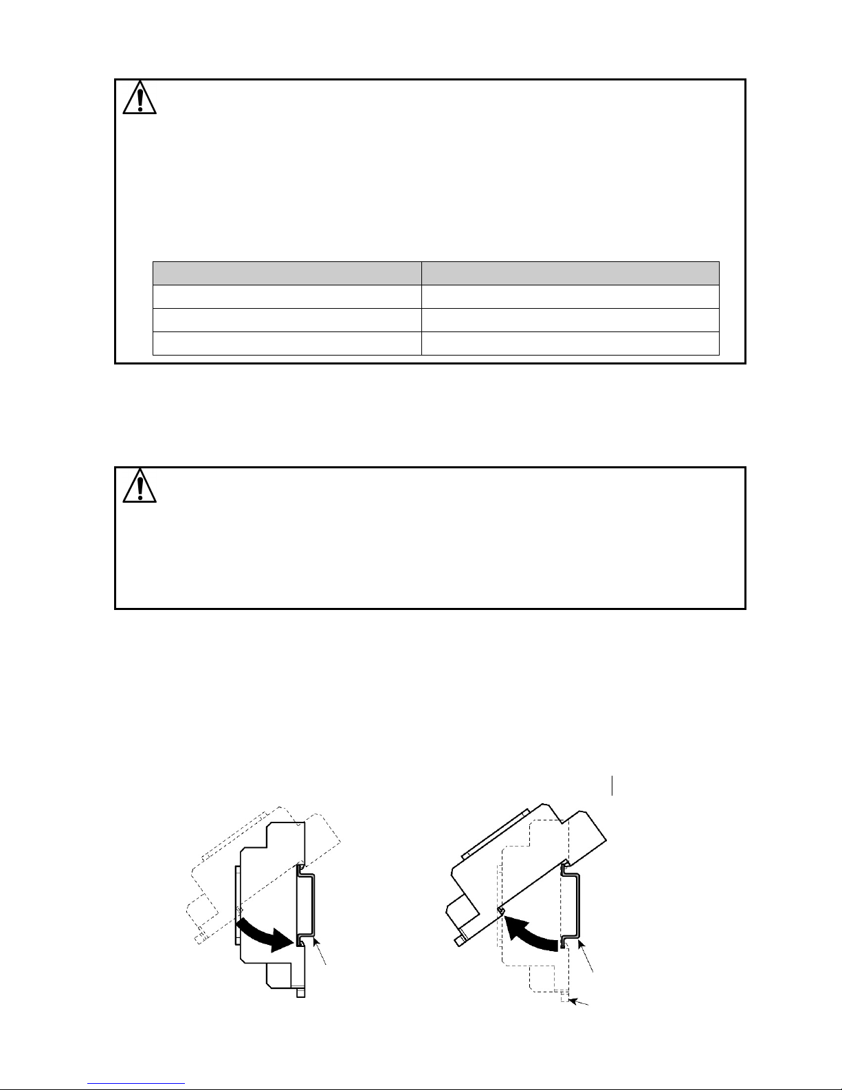
3.2 Mounting to, and Removal from the DIN Rail ......................................................10
4. Wiring .................................................................................................................................11
4.1 Lead Wire Solderless Terminal .............................................................................11
4.2 Circuit Configuration..............................................................................................11
4.3 Terminal Arrangement............................................................................................12
4.4 Wiring.......................................................................................................................13
5. Display Mode .....................................................................................................................14
6. Setting Mode......................................................................................................................16
6.1 Display Transition in Setting Mode.......................................................................16
6.2 Input Setting Mode .................................................................................................18
6.3 Output 1 Setting Mode ...........................................................................................20
6.4 Output 2 Setting Mode ...........................................................................................23
6.5 Instrument Setting Mode .......................................................................................26
6.6 Communication Setting Mode...............................................................................28
6.7 Custom Display Setting Mode...............................................................................30
6.8 Manual Mode ...........................................................................................................30
7. Adjustment.........................................................................................................................31
7.1 Basic Operation of Adjustment.............................................................................31
7.2 Adjustment ..............................................................................................................31
7.2.1 Output 1 Adjustment.......................................................................................31
7.2.2 Output 2 Adjustment.......................................................................................31
8.1 Indication after Power-on.......................................................................................32
8.2 Operation .................................................................................................................32
8.2.1 Input Indication Range....................................................................................32
8.2.2 Indication Range of Output 1 and Output 2..................................................32
8.2.3 Input Disconnection........................................................................................32
8.2.4 Indication Time Setting...................................................................................33
8.2.5 Ratio and Bias Settings ..................................................................................33
9. Specifications ....................................................................................................................37
10. Troubleshooting ..............................................................................................................40
10.1 Indication .................................................................................................................40
10.2 Key Operation .........................................................................................................40
10.3 Operation .................................................................................................................40
11. Character Table................................................................................................................41

5
1. Model
1.1 Model
SGB
S G B - □□□–0-□
Option
0: No option needed
1: Multi-rotation trimmer
2: Moisture-proof treatment
3: Multi-rotation trimmer + Moisture-proof treatment
Power supply
0: 100 to 240 V AC
1: 24 V AC/DC
Output*2
Input*1
Series name
SGBW
S G B W - □ □ □ □ - 0 - □
Option
0: No option needed
1: Multi-rotation trimmer,
2: Moisture-proof treatment
3:
Multi-rotation trimmer + Moisture-proof treatment
Power supply
100 to 240 V AC
Output 2*2
Output 1*2
Input*1
Series name
SGBL
S G B L - □□□– 0 - □
Option
0: No option needed
1: Multi-rotation trimmer
2: Moisture-proof treatment
3: Multi-rotation trimmer + Moisture-proof treatment
Power supply
0: 100 to 240 V AC
1: 24 V AC/DC
Output*2
Input*1
Series name (with Serial communication)

6
*1: Input
Code Input Type Code Input Type
A0
Direct
current
4 to
20 mA
(Built
-
in 50
shunt resistor
)
V0
DC
voltage
0 to 10 mV
(1
M
input resistance)
A1 4 to 20 mA
(250
shunt resistor)
V1 0 to 50 mV
(1
M
input resistance
)
A2 4 to 20 mA
(50
shunt resistor)
V2 0 to 60 mV
(1
M
input resistance)
A3 0 to 20 mA
(250
shunt resistor)
V3 0 to 100 mV
(1
M
input resistance)
A4 0 to 16 mA
(62.5
shunt resistor)
V4 0to1V
(1
M
input resistance)
A5 2 to 10 mA
(250
shunt resistor)
V5 0to5V
(1
M
input resistance)
A6 0 to 10 mA
(100
shunt resistor)
V6 1to5V
(1
M
input resistance)
A7 1 to 5 mA
(100
shunt resistor)
V7 -5 to 5 V
(1
M
input resistance)
A8 0 to 1 mA
(1000
shun
t resistor)
V8 0 to 10 V
(1
M
input resistance)
A9 10 to 50 mA
(10
shunt resistor)
V9 -10 to 10 V
(1
M
input resistance)
*2: Output, Output 1, Output 2
Code Output Type Code Output Type
1
Current
output
4
to
20
mA
A
Voltage
output
0
to
10
mV
2
0
to
20
mA
B
0
to
100
mV
3
0
to
16
mA
C
0
to
1
V
4
2
to
10
mA
D
0
to
5
V
5
0
to
10
mA
E
1
to
5
V
F
0
to
10
V
G
-
5
to
5
V
*
* Not available for SGBW.
1.2 How to Read the Model Label
The model label is attached to the left side of the case.
Terminal arrangement
Model (e.g. SGBW-A011-0-0)
Input (Enter a type selected in [Input type].)
Output 1 (Enter a type selected in [Output 1 type].)
Output 2 (Enter a type selected in [Output 2 type].)
Serial number
(Fig. 1.2-1)

7
2. Name and Functions
2.1 Front Panel
SGB, SGBL SGBW
①
③
④
⑤
⑥
①
③
④
⑤
⑥
⑦
⑧
⑨
⑩
⑦
⑧
② ②
(Fig. 2-1)
①
Display section
Indicates setting contents, input/output value.
②
Mounting screw
Used for fixing the instrument to the socket or removal from it.
③
DISP key
Switches the displays, and moves to the next setting item.
In Manual mode, Output 1 and Output 2 setting can be switched.
Releases the lock status of the DISP key by pressing for 3 seconds.
④
MODE key
Selects either a setting mode or a display mode.
Shifts the digit for the Custom Display.
Enters the setting mode by pressing and holding for 5 seconds.
⑤
UP key
Increases the numerical value.
Contents of Multi-Display A and B can be changed alternately
when Default Display is RUN display mode 1, 2*, 3, 4*, 5 and 6*.
⑥
DOWN key
Decreases the numerical value.
Enters Manual mode by pressing for 3 seconds.
⑦
Output
1
Z
ero
Adjusts the value of Output 1 Zero.
⑧
Output
1
S
pan
Adjusts the value of Output 1 Span.
⑨
Output
2
Z
ero
*
Adjusts the value of Output 2 Zero.
⑩
Output
2
S
pan
*
Adjusts the value of Output 2 Span.
* Only for SGBW

8
2.2 Display Section
SGB, SGBL SGBW
①
②
③
④
⑦
⑧
⑨
⑩
⑤
⑥
⑪①
②
③
④
⑦
⑧
⑨
⑩
⑤
⑥
⑫
⑬
⑭
⑮
⑯
⑰
⑱
⑪
⑬
⑭
⑮
⑯
⑱
(Fig. 2-2)
①
Setting display
indicator A
Lights up for the Setting display or Custom display.
②
Input indicator A
Lights up when Multi-Display A indicates an input value.
③
Alarm indicator A
Lights up if an input error or input disconnection occurs while
Multi-Display A indicates an input value.
④
Output indicator A
Lights up when Multi-Display A indicates an output value.
⑤
mA indicator
Lights up when mA is selected in [Indication unit].
⑥
% indicator
Lights up when % is selected in [Indication unit].
⑦
Setting display
indicator B
Lights up for the Custom display.
⑧
Input indicator B
Lights up when Multi-Display B indicates an input value.
⑨
Alarm
indicator
B
Lights up an input error or input disconnection occurs while
Multi-Display B indicates an input value.
⑩
Output indicator
B
Lights up when Multi-Display B indicates an output value.
⑪
1
indicator
A
Lights up when Multi-Display A indicates an input value, Output 1
output value, Input setting display or Output 1 setting display.
Is turned OFF when Multi-Display A indicates custom characters.
⑫
2
indicator
A
Lights up when Multi-Display A indicates Output 2 output value or
Output 2 setting display.
Is turned OFF when Multi-Display A indicates custom characters.
⑬
Multi
-
Display
A
Indicates the following in accordance with the display indication:
Input value, output value, custom characters, setting item
⑭
V indicator
Lights up when V is selected in [Indication unit].
⑮
°
C
indicator
Lights up when °C is selected in [Indication unit].
⑯
1
indicator
B
Lights up when Multi-Display B indicates an input value, Output 1
output value, Input setting display or Output 1 setting display.
Is turned OFF when Multi-Display B indicates custom characters.
⑰
2
indicator
B
Lights up when Multi-Display B indicates Output 2 output value or
Output 2 setting display.
Is turned OFF when Multi-Display B indicates custom characters.

9
⑱
Multi
-
Display
B
Indicates the following in accordance with the display indication:
Input value, output value, custom characters, setting value
Output indicators A and B, Alarm indicators A and B: Red
Other indicators: White
3. Mounting
3.1 External Dimensions (Scale: mm)
8P socket 11P socket
(Fig. 3.1-1)
DIN rail DIN rail

10
3.2 Mounting to, and Removal from the DIN Rail
Caution
•Mount the DIN rail horizontally.
•To remove the socket, a flat blade screwdriver is required.
Never turn the screwdriver when inserting it into the Lock lever. If excessive power
is applied to the lever, it may break.
• If the instrument is mounted in a position susceptible to vibration or shock, mount
commercially available fastening plates at both ends of the instrument.
Recommended Fastening Plate
Manufacturer Model
Omron Corporation End plate PFP-M
IDEC Corporation Fastening plate BNL6
Panasonic Electric Works Co., Ltd. Fastening plate ATA4806
Mounting to the DIN rail (Fig. 3.2-1)
①
Loosen the mounting screw on the front panel before removing the SGB from the socket.
②Make sure the lock lever of the socket is located in the lower part of the socket.
Hook the upper side of the socket onto the DIN rail, then fit the lower part of the
socket onto the DIN rail (A clicking sound should be heard when done properly).
Caution
•Before inserting the instrument to the socket, make sure the cable is wired properly.
(Refer to “4. Wiring”.)
•When inserting or removing the socket, make sure the socket is oriented vertically.
If force is applied in any other direction than vertically, a malfunction may occur.
•If the mounting screw is fastened too tightly, a malfunction may occur.
③Insert the SGB into the socket.
④Fasten the mounting screw by turning it clockwise, to secure the SGB onto the
socket. Tighten the screw lightly.
Removal from the DIN rail (Fig. 3.2-2)
①Turn the power to the instrument OFF.
②Separate the instrument from the socket by loosening the mounting screw on the
front panel.
③Insert a flat blade screwdriver into the Lock lever (lower part of the socket), and
remove the socket from the DIN rail while pulling the lever down.
(Fig. 3.2-1) (Fig. 3.2-2)
DIN rail
DIN rail
Lock lever

11
4. Wiring
Warning
Turn the power supply to the instrument off before wiring or checking.
Working on or touching the terminal with the power switched on may result in
severe injury or death due to electrical shock.
4.1 Lead Wire Solderless Terminal
Use a solderless terminal with an insulation sleeve in which an M3 screw fits as shown
below. The torque should be 0.63 N•m.
Solderless
Termina
l
Manufacturer Model
Y-type Nichifu Terminal Industries Co., Ltd. TMEV1.25Y-3
Japan Solderless Terminal MFG Co., Ltd. VD1.25-B3A
Ring-type Nichifu Terminal Industries Co., Ltd. TMEV1.25-3
Japan Solderless Terminal MFG Co., Ltd. V1.25-3
Y-type Ring-type (Scale: mm)
4.2 Circuit Configuration
SGB, SGBL
(Fig. 4.2-1)
SGBW
(Fig. 4.2-2)
Input
circuit Output
circuit
Communi-
cation
circuit
Modular
jack
Power
circuit
Front
trimmer
Display/
Setting key
circuit
+
-
+
-
1
4
9
12
13
14
CPU
For SGBL

12
4.3 Terminal Arrangement
SGB SGBL
(Fig. 4.3-1) (Fig. 4.3-2)
SGBW
(Fig. 4.3-3)
PWR Power supply 100 to 240 V AC or 24 V AC/DC
OUT (OUT1) Output or Output 1 (for SGBW)
OUT2 Output 2 (for SGBW)
A Direct current
input
V DC voltage
input
RS-485 Serial communication (for SGBL)

13
4.4 Wiring
Warning
• For 100 to 240 V AC, if the AC power source is connected to incorrect terminals,
the instrument will be burnt out.
(1) Power Source Wiring
SGB, SGBL: Use terminals ⑬,⑭for the power supply to the instrument.
For 24 V DC, use terminals ⑬(+), ⑭(-) for the power supply
to the instrument.
SGBW: Use terminals ⑩,⑪for the power supply to the instrument.
(2) Output Wiring
SGB, SGBL: Use terminals ⑨(+), ⑫(-) for the output wiring.
SGBW: Output 1: Use terminals ⑦(+), ⑧(-) for Output 1 wiring.
Output 2: Use terminals ③(+), ⑥(-) for Output 2 wiring.
(3) Input Wiring
SGB, SGBL: Use terminals ①,④for the input wiring.
SGBW: Use terminals ①,②for the input wiring.
(4) Communication Wiring
For the SGBL, connect the SGBL to SGBL using the provided cable.
(Fig. 4.4-1)

14
5. Display Mode
•: Available only for the SGBW.
Default Display: If the MODE and DISP keys (in that order) are pressed together
for approx. 3 seconds in any display mode, the display mode
will
become the Default Display.
Once the Default Display is set,
the DISP key will be in lock status.
• If the DISP key is pressed for approx.
3 seconds on the Default
Display, the key lock status will be cancelled.
If the DISP key is pressed while the DISP key is in lock status,
Multi-Display A indicates .
RUN display
mode 2
RUN display
mode 1
表示モード
1
DISP key
RUN display
mode 4
RUN display
mode 3
Default Display
RUN display
mode 5
MODE key
+
DISP key
for 3 sec
DISP key
MODE key
+
DISP key
for 3 sec
DISP key
MODE key
+
DISP key
for 3 sec
DISP keyMODE key
+
DISP key
for 3 sec
RUN display
mode 6
DISP key
MODE key
+
DISP key
for 3 sec
Custom display
mode 1
DISP key
MODE key
+
DISP key
for 3 sec
Custom display
mode 3
Custom display
mode 2
DISP key
Unlit display
mode
Custom display
mode 4
All unlit
display mode
MODE key
+
DISP key
for 3 sec
DISP key
MODE key
+
DISP key
for 3 sec
DISP key
MODE key
+
DISP key
for 3 sec
DISP keyMODE key
+
DISP key
for 3 sec
M
odel d
isplay
mode
DISP key
MODE key
+
DISP key
for 3 sec
DISP key
DISP key
MODE key
+
DISP key
for 3 sec
MODE key
+
DISP key
for 3 sec

15
RUN display mode 1
:
Multi-Display A indicates an input value, and Multi-Display B
ind
icates Output 1
output
value.
RUN display mode 2
:
Multi-Display A indicates an input value, and Multi-Display B
indicates Output 2
output
value.
RUN display mode 3
:
Multi-Display A indicates an input value, and Multi-Display B
is
unlit
.
RUN display mo
de 4
:
Multi-Display A indicates Output 1 output value, and
Multi
-
Display B
indicates Output 2
output
value.
RUN display mode 5: Multi-Display A is unlit, and Multi-Display B indicates Output 1
output
value.
RUN display mode 6: Multi-Display A is unlit, and Multi-Display B indicates Output 2
output
value.
Custom display mode 1: Multi-Display A indicates characters set in [Multi-Display A].
Multi
-
Display B indicates characters set in [Multi
-
Display B].
Custom display mode 2: Multi-Display A indicates an input value, and Multi-Display B
indicates the
characters
set in
[
Multi
-
Display B
]
.
Custom display mode 3: Multi-Display A indicates an Output 1 output value, and
Multi
-
Display B
indicates the characters set in [Multi
-
Display B].
Custom display mode 4: Multi-Display A indicates an Output 2 output value, and
Multi
-
Display B
indicates the characters set in [Multi
-
Display B].
Unlit display mode: Multi-Display A and B are unlit, and the Input indicator A lights
up.
Alarm indicator A and B light up if they are under the conditions
of lighting.
All unlit display mode
:
All displays and indicators are unlit.
Alarm indicator A and B do not light up even if they are under the
conditions of lighting.
Model display mode: Multi-Display A indicates a model name, and Multi-Display B
indicates an input code and output code.

16
6. Setting Mode
6.1 Display Transition in Setting Mode
•: Available only for the SGBW.
•: Available only for the SGBL.
• If the MODE key is pressed and held down for approx. 5 seconds in each setting mode,
the unit will move to the Default Display.
Default Display
Manual mode
(See p.30.)
DOWN
key
for 3 sec
MODE key, or
after Manual
mode auto
return time has
elapsed.
Returns to
the
Default Display.
Input setting
mode
(See pp.18-19.)
MODE
key
for
5
sec
DISP
key
for 3 sec
Input type
DISP
key
Decimal point place
Output 0% value
DISP
key
Output 100% value
DISP
key
Indication unit
DISP
key
Save settings
DISP
key
Returns to
the
Def
a
ult
D
isplay
.
DISP
key
Output 1
setting mode
(See pp.20-22.)
MODE
key
Output 1 type
DISP
key
for 3 sec
O
utput
1
decimal point place
DISP key
Indication value
at
output
0
%
Indication value
at
output
10
0
%
Output 1 low limit
Output 1 high limit
Output 2
setting mode
(See pp.23-25.)
MODE
key
DISP
key
for 3 sec
MODE
key
O
utput 1
Normal/Reverse
Save settings
DISP key
DISP key
DISP key
DISP key
DISP key
Output 1 ratio
DISP key
Output 1
bias
Input point 1
O
utput
1
output
value 1
Input point 2
O
utput
1
output
value
2
DISP key
DISP key
DISP key
DISP key
DISP key
DISP key
Returns to
the
Default Display.
DISP key
Output 2 type
O
utput 2
decimal point place
DISP key
Indicati
on value
at
output
0
%
Indication value
at
output
100
%
Output 2 low limit
Output 2 high limit
O
utput
2
Normal/Reverse
Save settings
DISP key
DISP key
DISP key
DISP key
DISP key
Output 2 ratio
DISP key
Output
2 bias
Input point 1
O
utput
2
output
value 1
Input point 2
O
utput
2
output
value
2
DISP key
DISP key
DISP key
DISP key
DISP key
DISP key
Returns to
the
Default Display.
DISP key

17
Instrument
setting mode
(See pp.26-27.)
Filter time constant
DISP
key
for 3 sec
Sensor correction
DISP
key
Indication time
DISP
key
Auto/Manual
DISP
key
Ratio setting
method
DISP
key
DISP
key
Communication
setting mode
(See pp.28-29)
MODE
key
Instrument number
DISP
key
for 3 sec
C
ommunication
speed
DISP
key
Data bit/Parity
DISP
key
Stop bit
DISP
key
R
esponse
delay time
DISP
key
DISP
key
Save settings
Returns to
the
Default Display.
DISP
key
Custom display
setting mode
(See p.30.)
MODE
key
Multi-display A
DISP
key
for 3 sec
Multi-display B
DISP
key
DISP
key
Save settings
Returns to
the
Def
a
ult
D
isplay
.
DISP
key
MODE
key
Save settings
DISP
key
To Input setting mode
Returns to
the
Default Display.
Manual mode
auto return time
DISP
key

18
6.2 Input Setting Mode
Input Type
Selects an input type.
Setting Range
Indicat
ion
Factory Default
Multi
-
Display A
Multi
-
Display B
4 to 20 mA
Built-in 50
shunt resistor
4 to 20 mA
Built-in 50
shunt resistor
4 to 20 mA
Externally mounted 250 shunt
r
esistor
4 to 20 mA
Externally mounted 50 shunt
r
esistor
0
to
20 mA
0
to
16 mA
2
to
10 mA
0
to
10 mA
1
to
5 mA
0
to
1 mA
10
to
50 mA
0
to
10 mV
0
to
50 mV
0
to
60 mV
0
to
100 mV
0
to
1 V
0
to
5 V
1
to
5 V
-
5
to
5 V
0
to
10 V
-
10
to
10 V
Decimal Point Place
Selects a decimal point place.
Setting Range
I
ndication
Factory Default
Multi
-
Display A
Multi
-
Display B
No decimal point
2 digits after
decimal point
1 digit after decimal point
2 digits after decimal point
3 digits after decimal
point

19
Output 0% Value
Sets an input value (indicated on the display) at the time of output 0%.
Setting Range
Indication
Factory Default
Multi
-
Display A
Multi
-
Display B
Low limit of each input type to
Output 100% value Set value
4.00
Output 100% Value
Sets an input value (indicated on the display) at the time of output 100%.
Setting Range
Indication
Factory Default
Multi
-
Display A
Multi
-
Display B
Output 0% value to
High limit of each input type Set value
20.00
Indication Unit
Selects the unit for indication.
Setting Range
Indication
Factory Default
Multi
-
Display A
Multi
-
Display B
No unit
No unit
%
mA
V
°C
Save Settings
Selects whether the settings are saved (registered) or not.
Setting Range
Indi
cation
Factory Default
Multi
-
Display A
Multi
-
Display B
Save Save
Not save

20
6.3 Output 1 Setting Mode
Output 1 Type
Selects an output 1 type.
Setting Range
Indication
Factory Default
Multi
-
Display A
Multi
-
Display B
4
to
20 mA
4 to 20 mA
0
to
20 mA
0
to
16 mA
2
to
10 mA
0
to
10 mA
0
to
10 mV
0
to
100 mV
0
to
1 V
0
to
5 V
1
to
5 V
0
to
10 V
-
5
to
5 V
*
* Not available for the SGBW.
Output 1 Decimal Point Place
Selects a decimal point place for Output 1.
Setting Range
Indication
Factory Default
Multi
-
Display A
Multi
-
Display B
No decimal point
2 digits after
decimal point
1 digit after decimal point
2 digi
ts after decimal point
3 digits after decimal point
Indication Value at Output 0%
Sets an indication value at the time of output 0%.
Setting Range
Indication
Factory Default
Multi
-
Display A
Multi
-
Display B
-1999 to 9999 Set value
4.00
Indication Value at Output 100%
Sets an indication value at the time of output 100%.
Setting Range
Indication
Factory Default
Multi
-
Display A
Multi
-
Display B
-1999 to 9999 Set value
20.00
This manual suits for next models
2
Table of contents
Other Shinko Transmitter manuals