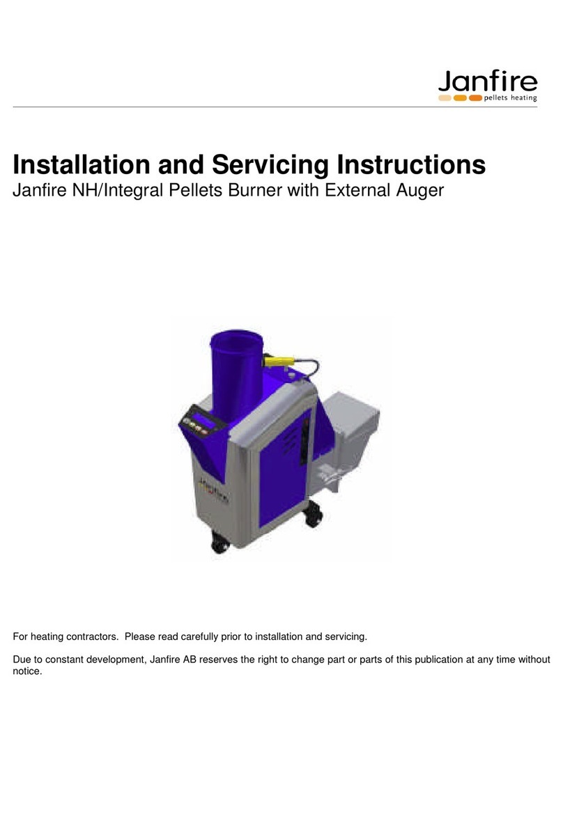
Janfire Flex-a Manual

Installation and Maintenance Instructions Janfire Flex 2a
Installation - Service
Pellet burner Janfire Flex-a
11899043 R2 SV
Janfire 2009

Installationsanvisning Janfire Flex - a
IA Brännare Flex-a R2 SV
Janfire 2009 2(19
)
Due to constant development, Janfire AB reserves the right to change part or parts of this
publication at any time without notice.
Janfire AB assumes no responsibility for errors or damages of any kind resulting from the use of
this publication.

Installationsanvisning Janfire Flex - a
IA Brännare Flex-a R2 SV
Janfire 2009 3(19
)
Contents
1 Safety Instructions.......................................................................................4
1.1 General Information .....................................................................................4
1.2 Conventions .................................................................................................5
1.3 Safety Instructions for Installation and Service.........................................5
1.4 Safety Systems ............................................................................................6
1.5 CE declaration ...............................................................................................6
2 Technical Data..............................................................................................7
3 Operational Description...............................................................................8
3.1 Pellet burner Flex-a........................................................................................9
3.2 Control panel................................................................................................11
3.3 Adjustment of various parameters................................................................12
3.4 Adjustment of the fan speed.........................................................................13
3.5 Adjustment of pellet Feeding........................................................................13
3.6 Adjustment of external augers running time .................................................14
3.7 Adjusting of maintenance time .....................................................................14
3.8 The Functional Description...........................................................................15
4 schema El ...................................................................................................17

Installationsanvisning Janfire Flex - a
IA Brännare Flex-a R2 SV
Janfire 2009 4(19
)
1 Safety Instructions
1.1 General Information
The security regulations base on a risk analysis that has been implemented according to relevant
EU directives in order to meet the European standards for CE labelling.
At each installation, the installation checklist completed and archived. This is very important to the
customer's warranty shall apply.
Read the safety instructions carefully before installation. Always follow the safety instructions
during installation and during maintenance. Follow the safety instructions on the warning signs!
Installation, operation, service and any other work should be carried out by qualified personnel and
in accordance to local standards and regulations.
When unpacking, the burner should be checked for any damage. If any parts are damaged contact
the installing contractor.
The local chimney sweep must be informed, an examination of the existing chimney must be
performed and a local building application may be necessary depending on local code
requirements.
Before using the system, it must be controlled and fine-tuned. Adjustments and readings are made
during start up. These observations should be written into the installation protocol. This is very
important in order to customer guarantee will apply.
NOTE: When restarting the system turn the burner fan on for 10 minutes to cool down any
remaining cinders.
NOTE: Always follow these instructions for installation, operation and service.
NOTE: For personal and operational safety: Use only spare parts, which have been manufactured
or approved by Janfire AB.

Installationsanvisning Janfire Flex - a
IA Brännare Flex-a R2 SV
Janfire 2009 5(19
)
1.2 Conventions
These safety instructions use the following protocols:
•DANGER!
The text “DANGER!” is used when there is a risk for personal injury or death.
•WARNING!
The text WARNING! is used when there is a risk for damaging the product, unit or control
box etc.
•CAUTION!
The text CAUTION! is used when there is a risk for a system failure, operational stop, or
disturbances etc.
The warning texts are in hierarchical order. The text “DANGER!” also includes the
possibility of the events covered by “WARNING!” or “CAUTION!”
1.3 Safety Instructions for Installation and Service
All electrical installation and service should be carried out by qualified personnel and in
accordance to local electrical standards and codes.
All plumbing and piping connections should be carried out by qualified personnel and in
accordance to local standards and codes.
Chimney cleaning should be carried out by qualified personnel and in accordance to local
standards and codes.
DANGER
High Voltage
inside
this equipment
DANGER
Rotating parts
DANGER
Risk of burns

Installationsanvisning Janfire Flex - a
IA Brännare Flex-a R2 SV
Janfire 2009 6(19
)
1.4 Safety Systems
The following safety systems are included in the Janfire NH pellet burner:
•A drop shaft protects against reverse combustion.
•Temperature switch
A temperature switch in the drop shaft stops the burner output if temperature
exceed 140°C .
•Water safety device.
The water safety device blows at an environmental temperature of 100°C.
NOTE: The container must be entirely filled with water. If the water safety device has opened and
released water or has begun to leak, then it has to be replaced.
•Feeding hose of plastics of a special type. The hose between the external
screw and the burner is made of plastics so that it shall melt away (not burn)
at high environmental temperatures and break the connection between the
pellets feeder and the burner.
•Circuit breaker
The NH pellet burner is equipped with a burner door micro-switch or circuit
breaker, which prevents the burner from operating when detached from the
boiler.
NOTE: The free space around the burner shall be in accordance with the authorities' requirements
regarding fire safety.
1.5 CE declaration
If the unit is used in combinations other than those tested, Janfire AB cannot guarantee compliance
with the relevant EU directives.

Installationsanvisning Janfire Flex - a
IA Brännare Flex-a R2 SV
Janfire 2009 7(19
)
2 Technical Data
Janfire Flex-a
Burner output capacity 9, 12, 15 och 18 kW
Maintenance output 600 W – automatic choice
Burner power consumption 80 W, 230 VAC, 50 Hz
Automatic ignition coil 1000 W
Pellet storage volume Internal storage: 3 liter = 1,8 kg
Internal dosage motor 15 W
Combustion fan 60 W, Variable speed operation
Control panel Touch-button
Fuses - 6 A circuit breaker (6A automatic fuse)
- 6,3 Amp fast blow fuse for heating coil
External auger 1-phase 230 V AC, 50 Hz, 250 W, 2,4 A, Capacitor 14 µF.
If auger length greater than 4.30 m, use a 3-phase motor.
Weight 25 kg
195
162
162
380
575
630
550
Figur 1 Måttskiss Janfire Flex-a

Installationsanvisning Janfire Flex - a
IA Brännare Flex-a R2 SV
Janfire 2009 8(19
)
3 Operational Description
An external auger feeds pellets from an external storage bin to a receptacle located in the top of
the burner (internal hopper). An internal dosage auger then feeds the pellets to a drop shut where
they fall freely into the combustion chamber or burning bowl/cup; this eliminates the possibility of
reverse combustion.
A variable speed fan supplies the burner with primary and secondary air. On its way to the burning
cup the air cools heat-exposed parts of the burner. The correct amount of air is then fed to the
burning cup for primary and secondary combustion. The ignition coil preheats the air for automatic
ignition. Burner cup sensor (flame guard) detects pellet ignition. If ignition does not take place shuts
the burner down.
OBS!
If the draft is insufficient the hot flue gases will rise backwards into the drop chute. If the drop
chute temperature rises to the highest allowed level 140°C shuts the burner down.
If it still is too
hot, the water safety device blows.
The power is determined by the chosen power level and is adjusted by the thermostat of the boiler.
Except for the standby output level of about 600 W, the burner output can be set between: 9 kW,
12 kW, 15 kW and18 kW. These burner output levels are based on a pellet weight density of 675
g/l and an energy content of 4.8 kWh/kg. To adjust for variations in the burner output and
combustion levels when using pellets with another weight or energy content the levels can be
changed here. The different output levels can be fine tuned to produce the best overall combustion
result.
High quality pellets produce high efficiency and output. High quality pellets are solid wood pellets
6-10 mm in diameter with little sawdust. Moisture levels should be no higher than 10%, ash
content no higher than 1% weight, and energy content should be about 4.7 - 5.0 kWh/kg. Always
verify the energy density and volume weight values for the pellets upon delivery.
Burner is intended for wood pellets according to SS 187120 group1-3(Sweden); DIN 51731 size
HP2 (Germany).

Installationsanvisning Janfire Flex - a
IA Brännare Flex-a R2 SV
Janfire 2009 9(19
)
Figur 2 Function description
3.1 Pellet burner Flex-a
1. Control panel is easily available and simple to use. It needs only a pressure on button
in order to start or to shut down. Automatic adaptation to summer or winter relation
gives best efficiency. Burner output can be adjusted after season, the building's size
and heat consumption. will be adjusted during installation. Burner output can thereby
easy be changed for most effective operation.
2. Good combustion with high efficiency and low wastes are achieved through that a
small internal auger be able precisely dose to the burner. Due to dosage auger can
pellet transport happen directly from bigger stores.
3. Automatic ignition.
4. Combustion Chamber is designed so that minimally with fuel submits the combustion
zone without to have been burnt up totally. None pellet ”spills over” and ports in the
boiler. Combustion Chamber is produced of heat-resistant stainless steels.
5. The combustion plate is very easy to lift out and clean.

Installationsanvisning Janfire Flex - a
IA Brännare Flex-a R2 SV
Janfire 2009 10(19
)
6. The burner is on wheels and therefore easy to move out for ash removal and cleaning.
It can easily be moved out of the boiler and avoid heavy lifting. Simple quick lock
fasteners - great for cleaning and ash removal.
7. Janfire flex-a can be obtained and adapted for upward burning or horizontally burning
flame and therefore suitable for almost all boilers.
8.
1
3
2
4
5
6
7
8
Figur 3 Pellet burner Flex-a

Installationsanvisning Janfire Flex - a
IA Brännare Flex-a R2 SV
Janfire 2009 11(19
)
3.2 Control panel
Functional description of the control unit. Explanation of the light signals and burning status
Note: Work with electrical parts of the plant should only be performed after the main fuse has disconnected,
and only by qualified personal
Buttons
STOPP = stopp/stand by
4 = 18 kW power
3 = 15 kW power
2 = 12 kW power
1 = 9 kW power
M = Manuell operation (15 kW)
Note !!! Ext Dos buttons can only
be activaded in Stop Mode
Ex t= Manuel operating of extern
motor
Dos = Manuel operating of
dosing motor
DIODER
Power indication
Alarm diodes
Operating indication
Edit button
Indication of diodes operating:
In each button for each power option there's a LED that can light up yellow, green or both yellow
and green.
When one of the power buttons activates lights diodes as follows:
Yellow and green ignition progress
Yellow and flashing green ignition progress-electric coil active
Green – Combustion running
Figur 4 Control panel

Installationsanvisning Janfire Flex - a
IA Brännare Flex-a R2 SV
Janfire 2009 12(19
)
Yellow-standby / maintenance burning
Diode at the stop button indicates when the burner is stopped or is being stopped (Flashing).
Alarm diodes:
Alarm diodes lights when interruption due to security or operational problems.
“Termokontakt “(temperature switch) Lights in case of the burner was subject to abnormal high
temperature caused by poor draft.
”Mikrobrytare” (safety switches) on the burner alerts if the burner is outside the boiler or are not
properly locked against the boiler
“Elspiral” (Ignition Coil) Faulty electrical coil or its electrical fuse
“Flamvakt” ( Flames detector) Burner has not managed to ignite the pellets or has extinguished
for some reason
“Extern motor” – Lights - alerts when filling of internal storage is not made within the time limit
“Extern motor” -Flashes – Broken TRIAC to external motor in the electronic circuit
All alarm settled (0) by breaking the power of the burner being until all diodes goes off and then
turn on the power again. Reset of over heating alarm requires that the burner has been cooled (the
Switch itself are automatically reset when the temperature in the burner falls down to normal
levels).
“Elspiral”( Ignition coil) broken ignition coil or its fuse
“Flamvakt (Flame guard) The Burner has not managed to ignite the pellets or has extinguished for
some reason
“Extern motor” (motor external auger) — illuminate when the filling of internal store is not made
within set time
Extern motor -flash when TRIAC is broken in electronics to external motor
All alarm been resetting (0) by breaking the power to the burner, until all diodes goes off, and turn
on the power again. Resetting of “termokontakt” (temperature switch) alarm requires that the
burner has been cooled (“termokontakten” are automatically reset when the temperature in the
burner falls down to normal levels).
3.3 Adjustment of various parameters
To be able to change some parameters must Electronics ' amendments (Edit) mode.
Turn on the change mode by pressing edit + Ext buttons in approximately 5 sec and release when
edit/Status diode is extinguished.
Note!!! Modify mode cannot be enabled during computer start-up or warming (transition between
maintenance and operation).
Each press of the button changes the edit mode in this order:

Installationsanvisning Janfire Flex - a
IA Brännare Flex-a R2 SV
Janfire 2009 13(19
)
•Fan preference mode
•Setting for feeding time
•Setting the external motor access time
•Setting for maintenance time end mode
3.4 Adjustment of the fan speed
Fan-preference mode activates by press both edit and Ext buttons in 5 sec and release when
edit/Status diode is switch off. When you release the buttons-edit/Status diode is blinking once.
This shows that fan-preference mode is active.
Select the fan mode will be adjusted by pressing each button as follows:
1 = Fan setting for the power mode 1 (60V)
2 = Fan setting for the power mode 2 (75V)
3 = Fan setting for the power mode 3 (90V)
4 = Fan setting for the power mode 4 (120)
M = fan setting for ignition (87V)
Connect the voltmeter to the underside of the burner and control the voltage.
Press “Ext” to reduce voltage
Press “Dose” to increase voltage
Press “Stop” to save the new setting.
If mode changes without saving returns settings to previously saved value.
3.5 Adjustment of pellet Feeding
Press edit button from Fan setting mode to activate feeding sttings mode.
Alarm diodes uses for display of feeding time.
Feeding time is normally 1.0 sec. In this case, only the diode in the middle (elspiral) shine.
Each press to Ext (left button) decreases time for 0.1 sec.
Each press to Dos (right button) increases time for 0.1 sec.

Installationsanvisning Janfire Flex - a
IA Brännare Flex-a R2 SV
Janfire 2009 14(19
)
For example, if the feeding time should be 1.1 sec then diodes for elspiral and mikrobrytare shine.
See other settings shown in the following figure. Feeding time can be adjusted between 0.6 and 1.4
sec.
Press STOPP to save the new setting.
¤
1,3
¤
1,4
¤
1,1
¤
1,2
¤
¤
0,9
¤
1,0
¤
¤
0,7
¤
0,8
¤
¤
0,6
¤
Edit
button
3.6 Adjustment of external augers running time
Press edit button from feeding settings mode to activate external augers settings mode.
Time is normally 2 min.
Only alarm diode at the bottom ”extern motor” shine.
One press to ”Dos” increase time for 1 min and turn on one diode more.
One press to ”Ext” decrease time for 1 min and turns out one diode.
For example, if the external augers running time should be 4 min then the three bottom diodes
(extern motor, flamvakt and elspiral) should shine.
Termokontakt = 6 min
Mikrobrytare = 5 min
Elspiral = 4 min
Flamvakt = 3 min
Extern = 2 min
Press “Stop” to save the new setting.
3.7 Adjusting of maintenance time
Press Edit from external auger settings mode to activate mode for adjusting of maintenance time.
Maintenance time is normally 60 min.”Termokontakt” diode at the top shine.

Installationsanvisning Janfire Flex - a
IA Brännare Flex-a R2 SV
Janfire 2009 15(19
)
Press the “Ext” button to decrease or “Dos” to increase time as shows in the figure. Press “Stop” to
save the new setting.
Om det önskas att brännare aldrig ska gå i underhåll ställer man tiden ner till 0. It is desired that the
burner should never go in the maintenance adjust time to 0.
Edit knapp
60 min
50 min
40 min
30 min
0
Press “Stop” to save the new setting.
Exit Edit mode by pressing the Edit button again and then Edit/status diode light up again
3.8 The Functional Description
Start:
Set the boiler's thermostat on the desired temperature (recommended around 80°C). The water
temperature in the boiler should be lower so that the thermostat is active.
If burner starts when the water temperature is higher or even just below (the thermostat switched
off), the burner goes on standby for at least 35 min (safety time) if the thermostat still switched off.
It is better to adjust the temperature and restart the burner to avoid wait according to the following:
Press “STOPP” button. Cut off the power. Wait until all the diodes on the Panel goes off. Turn on
the power again. Raise the thermostat, and select power level.
When the power level is selected (except "M" mode) starts the fan and blows on max rpm for 10
min (security blow).
To skip the security wind to do this, follow these steps:
"STOPP" is active. Boiler thermostat shall be switched on. Press the "ext" until extern auger
stops(in the case that the level of the filler pipe is below the sensor and the diode on the sensor is
off).Press and hold the "ext" key and select any effect mode (not "M") and the burner starts without
safety blow.
Start-up:

Installationsanvisning Janfire Flex - a
IA Brännare Flex-a R2 SV
Janfire 2009 16(19
)
After completed 10 min blow, starts feeding auger to feeding pellets (approx 60 sec), the fan starts
blowing (first 10 sec with max rpm and then turn to pulsing blow with ignition fan level) and at the
same time starts ignition coil warmed up for about 3 min and the Green diode on the selected
power button will Flash at the same time as the yellow diode lights up. See the functional diagram.
About 3 min after start the electrical coil power reduces to maintain a constant temperature of coil
(about 750 °C). The ignition coil switches off after about 7 min. Through the start-up uses ignition
fan level – which is factory set to 87 V.
Ignition occurs normally after 3 -4 min. After 5 min starts pellets feeding (first with longer pauses,
and then more often) and the fan starts blowing with more frequent pulses and then switch to
continuous speed. The whole start-up phase takes about 13 minutes.
Operation :
After the start-up phase, shifts it to the selected power level with preset feeding and fan speed.
Green diode on the selected power button will shine.
Now we can start adjustment at the different levels.
Feeding (quantity of distributed fuel) in each power level can be changed (see Chapter 5). The
feeding pulse is normally 1 second and with various breaks in the respective power level available
different quantities of pellets.
Air flow can be adjusted by adjusting the voltage to the fan in each level individually, so that a good
combustion is obtained.

Installationsanvisning Janfire Flex - a
IA Brännare Flex-a R2 SV
Janfire 2009 17(19
)
4 Inkopplingsschema El

Installationsanvisning Janfire Flex - a
IA Brännare Flex-a R2 SV
Janfire 2009 18(19
)

Installationsanvisning Janfire Flex - a
IA Brännare Flex-a R2 SV
Janfire 2009 19(19
)
Anteckningar:
Table of contents
Other Janfire Burner manuals
Popular Burner manuals by other brands

T&C
T&C TC42.NG05.C installation instructions

Town & Country Fireplaces
Town & Country Fireplaces D Series installation manual

baltur
baltur BPM 90 Original instructions

Dyna-Glo
Dyna-Glo DGB610SSP manual

Riello
Riello RS 190/M Installation, use and maintenance instructions

Jackson Grills
Jackson Grills JGSB-LP owner's manual

elco
elco VECTRON ECO 1.34 operating instructions

Bentone
Bentone BENTOFLEX ST 120 KA Installation and maintenance instruction

Kettler
Kettler NEO 6 Assembly, operation & maintenance instructions

Honeywell
Honeywell Eclipse ImmersoJet Design guide

Town & Country Fireplaces
Town & Country Fireplaces TCWS.38CE2 Manual for use

Midco
Midco Economite DS24A Installation and service instructions