Janfire NH User guide

Janfire NH Burner Service Installation Manual 3.31.09 - Technical specifications are subject to change without prior
notice. 1(38)
Installation and Servicing Instructions
Janfire NH/Integral Pellets Burner with External Auger
For heating contractors. Please read carefully prior to installation and servicing.
Due to constant development, Janfire AB reserves the right to change part or parts of this publication at any time without
notice.

Janfire NH Burner Service Installation Manual 4.16.09 - Technical specifications are subject to change without prior
notice. 2(38)
Contents
1 Safety Instructions 3
1.1 General Information 3
1.2 Conventions 3
1.3 Safety Instructions for Installation and Service 4
1.4 Safety Systems 4
1.5 Compliance Declarations 4
2 Technical Data 5
3 Operational Description 6
4 Boiler Installation 11
4.1 Boiler Evaluation 11
4.2 Mounting the Burner 12
4.3 Mounting and Elongating the Extension Auger 14
4.4 Pellet Level Adjustment 15
4.5 Pellet Volume Density Adjustment 16
4.6 Pellet Energy Density Value 16
4.7 Pellet Filling Before Starting the NH Burner 16
4.8 Calibration of Temperature Sensors 18
5 Starting and Stopping the NH Burner 19
5.1 Starting the NH Burner 19
5.2 Settings for Maintenance Fire 20
5.3 Stopping the NH Burner 21
6 NH Burner Set-up 22
6.1 NH Burner Draft Set-up and Control 22
6.2 Combustion Adjustments 22
7 NH Burner Menu System 24

Janfire NH Burner Service Installation Manual 4.16.09 - Technical specifications are subject to change without prior
notice. 3(38)
1 Safety Instructions
1.1 General Information
Read the safety instructions carefully before installation. Always follow the safety instructions during installation and
during maintenance. Follow the safety instructions on the warning signs!
Installation, operation, service and any other work should be carried out by certified and trained personnel and in
accordance to local standards and regulations.
When unpacking, the burner should be checked for any damage. If any parts are damaged contact the installing
contractor.
The local chimney sweep must be informed, an examination of the existing chimney must be performed per NFPA
guidelines and a local building application may be necessary depending on local code requirements.
Before using the system, it must be controlled and fine-tuned. Adjustments and readings are made during start up.
These observations should be written into the installation protocol section of this manual.
NOTE: Always follow these instructions for installation, operation and service.
NOTE: For personal and operational safety: Use only spare parts, which have been manufactured or approved by
Janfire AB.
1.2 Conventions
These safety instructions use the following protocols:
DANGER!
The text “DANGER!” is used when there is a risk for personal injury or death.
WARNING!
The text WARNING! is used when there is a risk for damaging the product, unit or control box etc.
CAUTION!
The text CAUTION! is used when there is a risk for a system failure, operational stop, or disturbances etc.
The warning texts are in hierarchical order. The text “DANGER!” also includes the possibility of the events
covered by “WARNING!” or “CAUTION!”

Janfire NH Burner Service Installation Manual 4.16.09 - Technical specifications are subject to change without prior
notice. 4(38)
1.3 Safety Instructions for Installation and Service
All electrical installation and service should be carried out by qualified personnel and in accordance to local
electrical standards and codes.
All plumbing and piping connections should be carried out by qualified personnel and in accordance to local
standards and codes.
All boiler cleaning or chimney cleaning should be carried out by qualified personnel and in accordance to local
standards and codes.
1.4 Safety Systems
The following safety systems are included in the Janfire NH pellet burner:
A non-combustible drop shaft protects against reverse combustion.
A temperature sensor in the drop shaft gives a reading which, if exceeds 158°F (70°C) reduces the
burner output. If the temperature exceeds 203°F (95°C), the burner shuts down.
A flexible tube of special plastic.
The tube between the external feeding auger and the burner is constructed of a special plastic
material, which melts (not burns) at high temperatures and breaks the contact between the pellet
feeding auger and burner.
Circuit breaker/Door switch
The burner is equipped with a micro-switch circuit breaker, which prevents the burner from operating
when detached from the boiler.
Two electrical fuses to protect electrical components from over current draws.
A 10 Amp resettable fuse is located above burner wiring terminal to protect internal electronics.
A 15 Amp fast blow fuse protects the ignition heating coil.
Speed sensor on the fan monitors fan speed.
NOTE: The Janfire NH pellets burner should have ample clearance in accordance to local codes.
1.5 Compliance Declarations
The Janfire NH burner has been tested and approved for use with the MESys 4000 and 6000 boilers and meets the UL
391-2006 and CAN/CSA B366.1-M91 standards. All electrical components of the Janfire NH burner are UL approved.

Janfire NH Burner Service Installation Manual 4.16.09 - Technical specifications are subject to change without prior
notice. 5(38)
2 Technical Data
Janfire NH Pellet Burner
Burner output capacity 10,000 – 78,000 Btu/hr (3 – 23 kW)
Maintenance output 2,000 Btu/hr (600 W)
Burner power consumption 80 W, 120 V AC, 60 Hz
Automatic ignition coil 1100 W
Pellet storage volume Internal storage: .75 gal (4 lbs) (3 litre = 1,8 kg)
Internal dosage motor 120 VAC, 60Hz
Combustion fan Variable speed operation
Self-cleaning burning chamber 120 VAC, 60Hz
Control panel Touch-button
Fuses - 10 Amp circuit breaker (reset table)
- 15 Amp fast blow fuse
External auger 1-phase 120 V AC, 60 Hz, 250 W, 4 A,
External auger cannot exceed 14 ft (4.30 m).
Weight 55 lbs (25 kg)
Figure 1. Dimensional drawing NH-burner (All measurements in mm)

Janfire NH Burner Service Installation Manual 4.16.09 - Technical specifications are subject to change without prior
notice. 6(38)
3 Operational Description
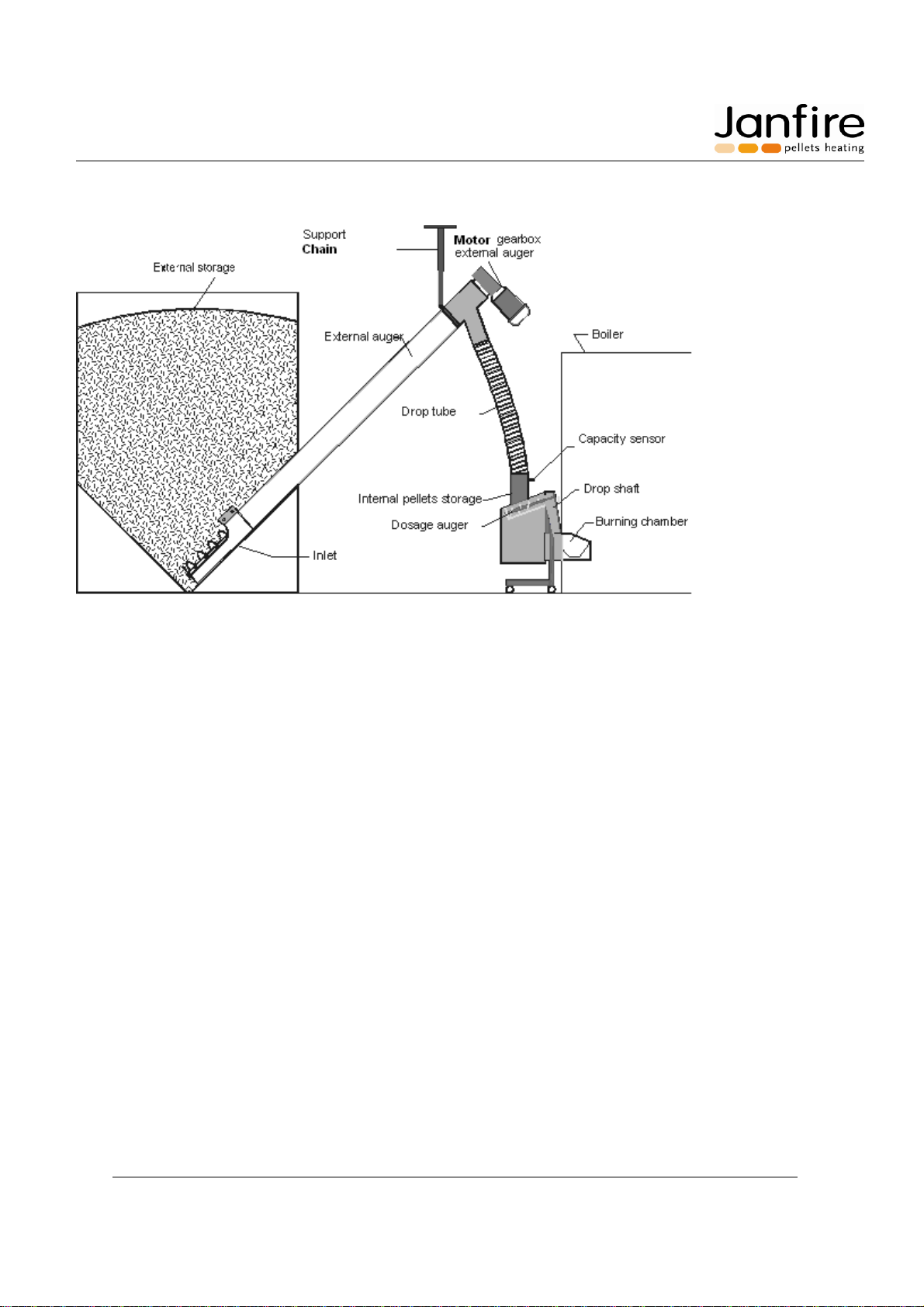
An external auger feeds pellets from an external storage bin to a receptacle located in the top of the burner
(internal hopper). An internal dosage auger then feeds the pellets to a drop shaft where they fall freely into the
combustion chamber or burning bowl/cup; this eliminates the possibility of reverse combustion.
A variable speed fan supplies the burner with primary and secondary air. On its way to the burning cup the air
cools heat-exposed parts of the burner. The correct amount of air is then fed to the burning cup for primary and
secondary combustion. The ignition coil preheats the air for automatic ignition. Burner up sensor (flame guard)
detects pellet ignition. If ignition does not take place, then the process repeats itself automatically and a new
ignition attempt is made. If ignition still does not take place after a pre-set number of trials, then the burner shuts
itself down.
If the draft is insufficient then the hot flue gases will rise into the drop shaft. The temperature sensor in the drop
shaft will detect this rise in temperature at 158oF (70oC). The burner will compensate by reducing the burner
output, thus eliminating the risk for reverse combustion. During this operation, the control lamp changes color to
yellow to indicate that the system is running in back-up level and the wording ”low chimney draft” will appear on
the display screen.
If the drop shaft temperature rises to the highest allowed level 203oF (95oC) then the burner will shut down
based on this temperature reading from the drop shaft temperature sensor. The control lamp will turn red and the
wording “Overheated” will appear on the display screen.
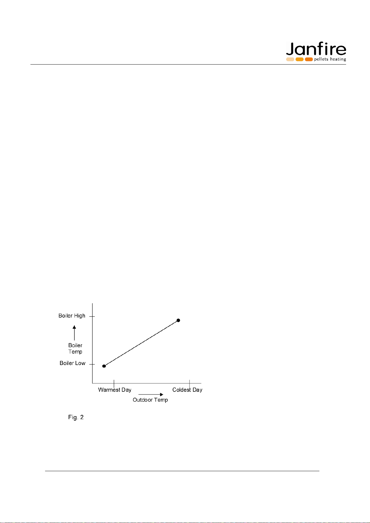
The burner input is controlled by a PID regulator using the boiler water temperature as input. Temperature is
measured with a PT-100 sensor placed in the boiler sensing well. The burner input is modulated automatically
between adjustable limits. The Min and Max input levels can be set from 10,000 to 78,000 Btu/hr (3 - 23 kW). If
no PT-100 sensor is connected to the burner, the burner input is controlled by pre-programmed ouput levels,
which are regulated with help of a thermostat. Except for the standby level of about 2,000 Btu/hr (600 W), the
burner input can be set between 10,000 to 78,000 Btu/hr (3 – 23 kW) in increments of 3,000 Btu/hr (1 kW).
These burner input levels are based on a pellet weight density of 5.77 lbs/gal (= 42.17 lbs/ft3 or 675 g/litre) and
an energy content of 7,420 Btu/lbs (4.8 kWh/kg). To adjust for variations in the burner input and combustion
levels when using pellets with another weight or energy content the levels can be changed here. The different
levels can be fine tuned to produce the best overall combustion result.
High quality pellets produce high efficiency and output. High quality pellets are solid wood pellets ¼” – 3/8” (6-
10 mm) in diameter with little sawdust. Moisture levels should be no higher than 10%, ash content no higher
than 1% weight, and energy content expressed as European Net Heat Value (ENHV) should be about 7,290 –
7,750 Btu/lbs** (4.7 - 5.0 kWh/kg). Always verify the energy density and weight density values for the pellets
upon delivery.
**Note: Contact your pellet supplier regarding the dry matter energy value, or European Net Heat Value
(ENHV), which is discounted for pellet moisture content as the Janfire NH burner requires this specific value. US
PFI (Pellet Fuel Institute) pellet standards at this point do NOT record this value and the PFI energy content
value can NOT be used directly.
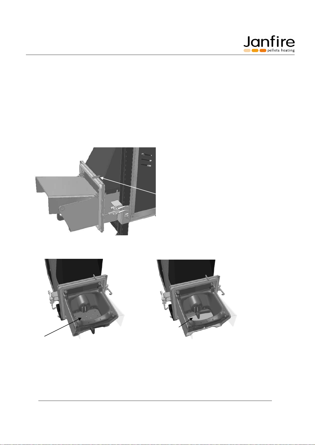
A patented moving base of the burning chamber scrapes away slag and waste material, feeding it into the boiler
firebox. The burner automatically cleans itself according to a signal from the boiler thermostat or based on pre-
programmed intervals (pellets consumption – 40lbs.).
PID regulator – function description
The PID regulator is commonly used to control processes in an efficient way. Here the PID regulates the burner
power level to reach the desired water temperature in the boiler. If the needed power is less than the minimum
power of the burner the temperature will increase to the upper temperature setting and the burner will go to
maintenance fire position.

Janfire NH Burner Service Installation Manual 4.16.09 - Technical specifications are subject to change without prior
notice. 7(38)
The regulator works with three factors:
P – Proportional power to temperature difference
I – Integrating power over time due to temperature difference
D – Differential power, due to rapid changes in temperature
For P and I factors, the difference between actual temperature and target temperature is used to calculate the
power output. If the actual temperature is 140°F (60°C) and the target temperature is 163°F (73°C), the
difference is calculated as 23°F (13°C).
The D-factor compares the actual temperature to the temperature at the last control position. If there is any
difference, this will be multiplied with the D-factor and the burner power will change thereafter.
The result from the above values will be added together to calculate the new required power output level for the
burner.
Example:
Nominal power, start up power: 20 MBTU
Regulation interval: 1:00 min
Power level min: 20 MBTU
Power level max: 51 MBTU
P-factor: 10000%
I-Factor: 500%
D-factor : 0%
Boiler temperature: 140°F (60°C)
Target temperature: 163°F (73°C)
Temperature difference = 73 – 60 = 13
P = 10000% x 13 = 1300
I = 500% x 13 = 65
D = 0% x 0 = 0
Sum of P + I + D = 1365.
This added to nominal, start up, power 600 (6kW, 20 MBTU) 1365 + 600 = 1965. The output is in units of 10 W
so 1965 will be (19.6 kW) 67 MBTU. Since the maximum power level is set to (15kW) 51MBTU, the power will
be limited to that. The integrating (I-value) memory starts with nominal power, and will get the new value of 665.
If the boiler temperature is higher than target, the P- and I-factor will decrease power output.
The PID regulator will come in balance when actual and target temperatures are equal. The P factor will then be
0 and the integrating memory will hold the power level.
The P factor determines how much power the burner will provide due to a temperature difference.
The I factor specifies how fast the burner will increase / decrease power over time.
The D factor is often used in fast processes to stop controller from over shooting. It is not very usable in this
slow process.
The control interval determines how often calculations and changes in burner output settings are made.
Power modulation
In order to modulate burner output, a PT-100 sensor measuring the boiler water temperature must be
connected. PID Control must be activated, “service menu 66”.

Janfire NH Burner Service Installation Manual 4.16.09 - Technical specifications are subject to change without prior
notice. 8(38)
The modulation power is used to achieve longer working periods, minimizing the number of starts and stops. The
settings should be made so that the burner rapidly reaches target water temperature, and so that burner power
will be sufficient to take sudden increase in power consumption. The settings should also be able to decrease
power levels fast enough when target temperature is reached so that a balance in power is achieved. The
settings should let the burner operate within 10 – 18°F (6-10°C) beyond the target temperature before it stops,
as this range is required to handle changes in power output.
Thermostat hysteresis is set in “Service menu 64 –Differential below target” and “Service menu 65 – Differential
above target”. Default PID factors are P = 20,000%, I = 2,000% and D = 0%. These setting can be used in most
cases. If PID is inactivated, OFF in “service menu 66”, the burner works with the nominal, start-up, power level. If
no PT-100 sensor is connected the service menus 64-70 will be hidden and the burner will be controlled by the
thermostat and work on nominal, start-up, power level if “External thermometer – YES” selected.
Outdoor temperature modulation
In order to modulate boiler water setpoint temperature, a second PT-100 sensor measuring outdoor temperature
must be connected. (Standard supplied with the burner.)
Outdoor temperature will control boiler water temperature as follows:
68°F (20°C) or higher outdoor temp: Boiler temperature is equal to 140°F (60°C).
-4°F outdoor temperature or below: Boiler temperature equal to 185°F (85°C).
This function is active only if “Outdoor temp controls, service menu 78” is set to “YES” and the “Extra input as”,
at service menu 77 is set to “Outdoor”.
The outdoor temperature is sampled every 5 or 10 minutes, “service menu 79” and an average value is
calculated. This value is compared with the last sample, and a new target temperature is set if value has
changed. Maximum allowed change for target value is 1.8°F (1°C) each sample period even if calculated change
is greater.
The factor set heating curve is defined by parameters 81 – 84. One defines beginning and end points of the
heating curve by listing 2 boiler water and corresponding outdoor temperatures. These 2 data points define the
heating curve. Refer to service menu points 81 – 84 for details.

Janfire NH Burner Service Installation Manual 4.16.09 - Technical specifications are subject to change without prior
notice. 9(38)
Fitting Instructions for Outdoor temperature sensor
Location: If the rooms which temperature is to be regulated all face the same direction (same cardinal point) the
temperature sensor has to be placed on that side.
In any other case, see to it that the temperature sensor is placed on the coldest side of the building (north,
northeast).
The temperature sensor is not to be fitted over windows or doors because of outstreaming warm air, neither
should it be placed in a recess (niche) in the wall.
Figure 3. Micro switch
Figure 4. Ash scrape moving base
The moving base of the burning chamber scrapes away slag and waste material, feeding it into the boiler firebox based
on pre-programmed pellets consumption.
A micro switch prevents the burner from
operating when detached from the boiler
bulk head.
The moving base in
operational position
The moving base
in cleaning position

Janfire NH Burner Service Installation Manual 4.16.09 - Technical specifications are subject to change without prior
notice. 10(38)
Pellet boiler and NH pellet burner system complete with fill auger and pellet storage.
Figure 5. Function description

Janfire NH Burner Service Installation Manual 4.16.09 - Technical specifications are subject to change without prior
notice. 11(38)
4 Boiler Installation
4.1 Boiler Evaluation
Before the burner is installed the following aspects should be considered:
The boiler desired output level
Premium pellet energy density and volume density
Ash container
Ash is collected at the bottom of the boiler without disturbing the flow of flue gases. The boiler convection areas
absorb the heat from the passing flue gases. These areas should periodically be cleaned with a brush. The
MESys 4000 – 6000 boiler is a low pressure hot water boiler and the fire box pressure should be about -10 Pa (-
.04 inches WC) at full fire operation. An adjustable barometric damper must be used to limit draft.
Water volume
The water volume of the boiler bears no great importance. Because a thermal storage or DHW tank with heating
coil is recommended as it will cause the burner to run more effectively with longer combustion periods and fewer
start ups and shut downs.
Manual Reset High limit control and low water cut-off
NOTE: A manual reset high limit temperature control and manual reset low water cut-off must be used as
additional safety controls in addition to the PT-100 burner controller. The manual reset high limit control will shut
down the electrical supply to the burner in case of a high temperature condition. The low water cut-off shuts
down the burner in case of a low water condition.
Combustion Air
The Janfire NH pellet burner requires ample fresh air for combustion to ensure proper operation. Check ventilation
openings for blockages.
Ensure required size of free combustion air opening(s) in sq. ft. to be at least equal to three times the cross
sectional area of the chimney.
IMPORTANT NOTE: Make sure that the boiler room has adequate combustion air and that this space can
NEVER be pulled into a negative pressure condition. Check the following:
-Keep fire place dampers closed at all times to avoid negative pressure.
- Make sure that power venters, exhaust fans, central vac systems and other air moving equipment do
NOT interfere with the pellet burner operation.

Janfire NH Burner Service Installation Manual 4.16.09 - Technical specifications are subject to change without prior
notice. 12(38)
4.2 Mounting the Burner
The boiler lower front door has a pre-made opening for the burner.
1. Locate the eyelets shipped with the burner.
2. Screw in the eyelets into the tappings directly adjacent to the burner bulkhead opening.
3. Unpack the burner and remove plastic transporter handle. Check the integrity of the burner/ boiler
sealing braid.
NOTE: To achieve the best output from your system the boiler must be airtight. The sealing gasket
between boiler and burner must be airtight to stop any extra air from entering the system.
4. Check if flame deflector is in place and place the burner into the boiler; adjust eyelets on the boiler
bulkhead then lock burner in place.
NOTE: Make sure that the burner door insulation remains intact after burner insertion. Add high
temperature insulation (not supplied) if necessary between burner flame deflector and burner door
insulation.
5. Adjust the burner’s height by releasing the locking screw and lowering the support wheels. Tighten the
locking screw when the correct height is achieved.
6. Attach the burner electrically to the boiler aquastat according to Fig. 15 electrical wiring diagram.
7. The NH pellet burner is supplied with an outdoor sensor and boiler sensor. Attach the common sensor
wiring box to the right side of the boiler. Route the boiler sensor underneath the boiler top jacket panel
to the boiler well located in the top of the rear boiler section.
8. Combine the NH burner boiler sensor along with Honeywell capillary and blocking spacer into the
immersion well. Make sure all sensors are fully inserted into the well. Screw Honeywell aquastat to top
of jacket panel. (see Fig. 6)

Janfire NH Burner Service Installation Manual 4.16.09 - Technical specifications are subject to change without prior
notice. 13(38)
Fig. 6 – Well Assembly
9. Route the outdoor sensor to a location on the north side of the house. Splice in shielded low voltage
wire if additional length is required. Make sure to locate the sensing element out of direct sunlight, away
from rain and direct weather exposure and well above the snow line.
NOTE: A manual reset high limit temperature control must be used as an additional safety control in addition
to the PT-100 burner controller. The manual reset high limit control will shut down the electrical supply to
the burner during a high temperature condition. Refer to Fig. 15, pg. 37 for wiring instructions.
All electrical installation and service should be carried out by qualified personnel and in accordance to local
standards and codes.
Aquastat bulb
Corrugated spacer
Pie shaped spacer
PT100 Sensor

Janfire NH Burner Service Installation Manual 4.16.09 - Technical specifications are subject to change without prior
notice. 14(38)
4.3 Mounting and Elongating the Extension Auger
1. Mount the auger according to Figure 7 Auger attachment
M6x16
M6x30 M8x30
insex M8x30
ins M8x30
Figure 7 Auger attachment
NOTE: The more compact part of the auger should always be mounted at the end of the external auger.
NOTE: In no circumstances shall a vacuum feed pellet delivery system be installed to the burner.
2. Adjust suspension chain of external auger so that auger outlet is only slightly offset above the internal
hopper of burner with burner in place (see Figure 5. Function description). Make sure the burner drop
tube is nearly vertical.
NOTE: Ensure secure mounting to avoid risk for the auger to fall.
3. To maximize emptying of the external pellet storage, the inlet of the auger should be placed as centrally
in the storage bin as possible.
4. Connect the 3-wire cord contact from the burner to the corresponding terminals on the external motor
(See Fig. 15 for wiring instructions). Check proper rotating direction of feeding auger; refer to auger
motor wiring for rotation reversal.
NOTE: Do not touch the dosage auger or the external augers in or outlet openings when the external
feeding motor is connected.
Fasten the drop tube to the external auger outlet and to the burner hopper inlet with the supplied hose clamps,
use a little soapy liquid on the inside of the tube to ease the sliding. Avoid sharp bends or slack in the drop tube
that can cause a blockage in the external auger. Cut off excess length with a sharp knife.

Janfire NH Burner Service Installation Manual 4.16.09 - Technical specifications are subject to change without prior
notice. 15(38)
4.4 Pellet Level Adjustment
The level control for the burner is pre-programmed. Its sensitivity can however be affected during transportation
or after operational time (about 2 weeks) and may require adjusting. In all cases, at start-up, perform the steps
below to ensure sensor sensitivity compliance.
1. Stop the burner. The main circuit breaker must be turned on so that there is operational power.
2. Loosen and remove the drop tube from the burner inlet.
3. Test with your finger to see if the diode lights up at a distance of 3/8” (8-9 mm), see Figure 8 Level
adjustment below.
4. Use a screwdriver and unscrew the cover plug, as you now can reach the adjustment screw. Turn the
screw inside the hole until the correct distance is reached 3/8” (8-9 mm). Counter-clockwise rotation
reduces sensitivity; the sensor reacts at a shorter or reduced distance. Clockwise rotation increases the
sensitivity; the sensor reacts at longer distances.
Figure 8 Level adjustment
NOTE: The adjustment screw is very sensitive and requires no more than a few degrees of rotation in either
direction. Be very careful not to turn screw too hard.
5. Reinstall the cover plug and drop tube and secure with the furnished clamps.
Adjustment screw
LED (yellow)
Cover plug
3/8”

Janfire NH Burner Service Installation Manual 4.16.09 - Technical specifications are subject to change without prior
notice. 16(38)
4.5 Pellet Volume Density Adjustment
To achieve good combustion and the least amount of exhaust products, it is very important to indicate the
correct volume density of the pellets. The correct value can be supplied by your pellets supplier or by weighing.
The average weight per litre of pellets is 5.77 lbs/gal (42.17 lbs/ft3 or 675 gr/liter). When adjusting this value, the
dosage time is also changed (automatically) to compensate accordingly, resolve discrepancies and to ensure
good combustion.
If the weight setting is not correct, poor combustion will occur. Tar can build up in the combustion chamber and
burning cup and malfunction could be the result.
To weigh pellet fuel sample: Fill a 5 gal container with pellets and weight it on a scale. Make sure to subtract
the empty weight of the container. Compute net weight per gal by dividing by 5. Record net weight in lbs.
Multiply now by 7.31 to get lbs/ft3 and program this value into the NH burner.
To change the weight density setting: Scroll or repeatedly push the “menu” button until you come to “Volume
Weight xxx lbs/ft3” and change by pushing the “-“ and “+” buttons.
To save the new weight density setting: Press and hold down the “menu” button for 3 seconds.
4.6 Pellet Energy Density Value (ENHV)
To achieve good combustion and reduced exhaust gases, the correct energy density value for the pellets is
required and must be inputted into the burner. Your pellet supplier can supply this information.
The European Net Heat Value (ENHV) for a pound of pellets at 100% dry matter is expressed as 7.420 Btu/lbs
(4.80 kWh/kg). Always check with your pellet supplier regarding it’s ENHV value! When this value is changed in
the burner controller, the dosage auger feeding time is also changed (automatically) to compensate for any
deviations in the energy density value and to ensure good combustion.
To change the energy density value: Press the menu button repeatedly until “Energy density xxx Btu/lbs” is
shown and change its value by pressing the “-“ or “+” buttons.
To save the energy density value: Press and hold down the “menu” button for 3 seconds.
Selection of NH Burner Output Value.
WITH PT-100 boiler water temperature sensor:
In this mode the burner output will modulate between two preset limits by using the PID regulator. The
modulation function can be inactivated in menu step 66. If modulation is inactivated, the NH burner will run at a
fixed output level, see text below.
Volume weight:
XX lb/ft
3

Janfire NH Burner Service Installation Manual 4.16.09 - Technical specifications are subject to change without prior
notice. 17(38)
To select the max firing rate: nominal effect level: Press “menu” button repeatedly until “Select powerlevel. Xx
Mbtu” is shown. Change its value by pressing the “-“ or “+” buttons. The output can be adjusted between limits
for modulating effect in steps of 3,000 Btu (normal 20,000 – 78,000 Btu/hr).
To save new value: Press and hold down the “menu” button for 3 seconds.
The max firing rate is the starting point for the burner when running in modulating mode.
4.7 Pellet Filling Before Starting the NH Burner
The external auger can only feed the pellets to the burner if the external storage tank pellet level is above the
external auger’s inlet.
1. Fill the external storage.
2. Fit burner to the boiler by using the quick locking latches on each side. Make sure that the gasket
between burner and boiler door is tight when the door has been locked.
3. Verify power cables from boiler high limit to burner and from external feed motor are connected to their
respective inputs on the burner, check status of the drop tube, turn on power (burner power supply must
also be turned on). After a few seconds “Waiting for pellets” is displayed on the display screen the
external feeding auger starts. This auger stops after 2 minutes if the internal hopper is not filled within
that timeframe. Press the “ON/OFF” button and the auger continues to run. Continue this process until
the correct level is reached. When the internal hopper is full, the level sensor stops the external auger.
NOTE: The main power switch is usually located on the wall next to the boiler or by the entrance to the boiler
room.
Manual Feeding
4. The external auger can be used manually: Press “ON/OFF” to stop. Scroll menu until you come to
“manual external auger”, then press and hold the “+” button to start the motor. Fill until the burner
internal storage is full. The motor stops when the “+” button is released or when the internal storage
sensor is activated.
NOTE: “Manual external auger” is shown only when burner operation is stopped.
NOTE: Do not touch the dosage auger or the external augers in- or outlet when the external motor is connected.
The capacity sensor activates when the pellet level in the internal storage has fallen below the sensor area.
Under normal running conditions the external auger runs up to 2 minutes after the capacity sensor has switched
on. This control is programmed so that the motor will only run for 2 minutes at a time. If the burner internal
storage has not been filled in this time frame, the indication lamp changes color from green to red and the
“!!ERROR!!! External feed” appears on the display screen.

Janfire NH Burner Service Installation Manual 4.16.09 - Technical specifications are subject to change without prior
notice. 18(38)
4.8 Calibration of temperature sensors
Calibration may need to be done prior to burner start up. Burner will be in the boiler-room so that all parts in
burner are at room temperature.
Enter service menu row “75 Offset internal” and see temperature there. It will show room temperature (perhaps
70oF).
Go then to rows: “71 offset burner bowl” and “72 backburn” and with the aid of offset adjust in temperature so
that it shows the same as “75 Offset internal”.
To change: briefly press the “menu” button (temperature numbers flashing) and then adjust using the “+” and “-“
buttons until the temperature is correct.
To save: Press and hold down the “menu” button for three seconds.
NOTE: Temperature on 71 (and 72) does not go to set lower than “75 Offset internal”.
“73 Offset Boiler temperature will be adjusted in the same way, But in this case, it must be adjusted to show its
actual temperature.
“75 Offset Outdoor” wil be adjusted to the outdoor temperature.

Janfire NH Burner Service Installation Manual 4.16.09 - Technical specifications are subject to change without prior
notice. 19(38)
5 Starting and Stopping the NH Burner
5.1 Starting the NH Burner
1. Install the burner into the boiler and lock it in place on both sides with the locking latches.
NOTE: The burner should be secured tightly so that no embers or smoke can be released. A non-
airtight connection can lead to a poor combustion and poor burner operation.
2. Verify that there are sufficient pellets in the external storage. The pellet level should never be lower than
the external auger inlet.
3. Check that power cables between burner and boiler and between the burner and external auger are
connected. Check that the drop tube between the external auger motor and burner internal hopper is
securely in place.
4. Turn on main power switch.
NOTE: The main power switch is usually located on the wall next to the boiler or by the entrance to the
boiler room.
5. After power is applied, press “ON/OFF” if “Stop waiting” shows in the display. The NH Burner will
execute an ashscrape, the external auger will feed pellets for up to two minutes and the ignition process
will begin. You may stop the process by pressing on/off once – “Stop waiting”. Press on/off again to
resume start up.
6. To change the desired output: Scroll the “menu” button until you come to “Choose output level xx Mbtu”.
Change value by pressing the “+” and “-“ buttons. Save the new level by pressing and holding down the
“menu” button for 3 seconds, “Saved to memory” will appear on the display screen. The next time the
burner starts, it will use the last saved value.
7. To achieve a good combustion with low exhaust temperatures, the value of the pellet weight density and
energy density values must be correct. Adjust both as described in sections 4.5 and 4.6.
If the boiler high limit is closed, the internal hopper is filled (approx. 2 min.) then the pellet level is above the
sensor. The burning cup is cleaned next. This then starts the ignition sequence of the burner. Pellets are fed
into the burner with the dosage auger, the ignition coil is energized and the combustion air fan starts. The start
sequence is pre-programmed to deliver a fast ignition and low exhaust levels. The start-up sequence takes
about 10 minutes after which the chosen output level is reached.

Janfire NH Burner Service Installation Manual 4.16.09 - Technical specifications are subject to change without prior
notice. 20(38)
5.2 Settings for Maintenance Fire
The maintenance fire position is automatically controlled by the burner. The maintenance fire position
represents a low fire, small continuous output level of about 2000 Btu/hr designed to allow burner restart without
the ash scrape cleaning function. It allows continued operation without the need to restart the ignition process.
Depending on the length of the previous maintenance period, the burner will automatically determine whether to
go into this “maintenance” mode. The time limit for this is set in “menu step 56”, default setting 1:00 hour.
* Last maintenance period shorter than time in “menu step 56”, burner will run in maintenance mode.
* Last maintenance period longer than time in “menu step 56”, no maintenance fire mode.
The maintenance mode is specifically designed to keep a very small fire (2000 Btu/hr) in the burner and allow
continued burner operation without automatic ignition. The burner operates normally to maintain desired water
temperature.
Table of contents
Other Janfire Burner manuals
Popular Burner manuals by other brands

T&C
T&C TC42.NG05.C installation instructions

Town & Country Fireplaces
Town & Country Fireplaces D Series installation manual

baltur
baltur BPM 90 Original instructions

Dyna-Glo
Dyna-Glo DGB610SSP manual

Riello
Riello RS 190/M Installation, use and maintenance instructions

Jackson Grills
Jackson Grills JGSB-LP owner's manual

elco
elco VECTRON ECO 1.34 operating instructions

Bentone
Bentone BENTOFLEX ST 120 KA Installation and maintenance instruction

Kettler
Kettler NEO 6 Assembly, operation & maintenance instructions

Honeywell
Honeywell Eclipse ImmersoJet Design guide

Town & Country Fireplaces
Town & Country Fireplaces TCWS.38CE2 Manual for use

Midco
Midco Economite DS24A Installation and service instructions