JANSKA RHC-3092 User manual

Models:
RHC-3092 (30in)
RHC-3692 (36in)
RHC-4892 (48in)
USER MANUAL
UNDER-CABINET
RANGE HOOD
Your satisfaction is guaranteed. If you are not completely satisfied with our
Under-Cabinet Range Hood and the results it brings, we insist that you let us
know. We’ll help make the Range Hood work for you, or we’ll refund your money.
SWEDEN

IMPORTANT SAFETY INSTRUCTIONS……………………………………………...............………
INSTALLATION REQUIREMENTS ………………………………………………….......…………….
Parts Supplied …………………………………………………………….........................…….
Location Requirements ………………………………………………......………………………
Ventilation Requirements ……………………………………….........………………………….
Electrical Requirements ……………………………………........................…………………..
INSTALLATION INSTRUCTIONS ………………………………………...…………………………....
Prepare Location ………………………………………………………......……………………..
Venting Methods ………………………………………………………...………………………..
Advanced Preparation………………………………………….............................……………
Install the Range Hood ………………………………………………………………………….
RANGE HOOD USE …………………………………….......................……………………………..
Range Hood Controls ……………………………..............………………..………………….
Operating the Range Hood……………………….............……………………………………
Remote Control……………….............…………......................................…………………
RANGE HOOD CARE ………………………………………………………………….………………
Cleaning & Maintenance ……………………………………………………………………….
TROUBLESHOOTING ………………………………………………………………………………….
SPECIFICATIONS ………………………………………………………………………………..…….
2
4
4
5
5
6
7
7
7
8
9
12
12
12
13
14
14
15
16
TABLE OF CONTENTS
WARNING
This indicates that death or serious injuries may occur as a result of non-observance of
this warning.
CAUTION
This indicates that minor or moderate injuries may occur as a result of non-observance
of this warning.
NOTICE: This indicates that damage to the appliance or property may occur as a result
of non-compliance with this advisory.
Note: This alerts you to important information and/or tips.
SAFETY DEFINITIONS
1

WARNING: TO REDUCE THE RISK OF FIRE, ELECTRIC SHOCK, OR INJURY TO
PERSONS, READ THE FOLLOWING:
• Use this unit only in the manner intended by the manufacturer.
• Make sure that the voltage indicated on the rating plate of the appliance corresponds to
your outlet voltage.
• Do not attempt to alter the technical features of the range hood as this poses a safety risk.
• Installation work and electrical wiring must be done by a qualified professional(s) in accor-
dance with all applicable codes, standards, and fire-rated constructions.
• DO NOT attempt to install this appliance yourself. Injury could result from installing the
unit due to lack of appropriate electrical and technical background.
• The manufacturer does not accept any liability for any damage or injury caused by
improper installation.
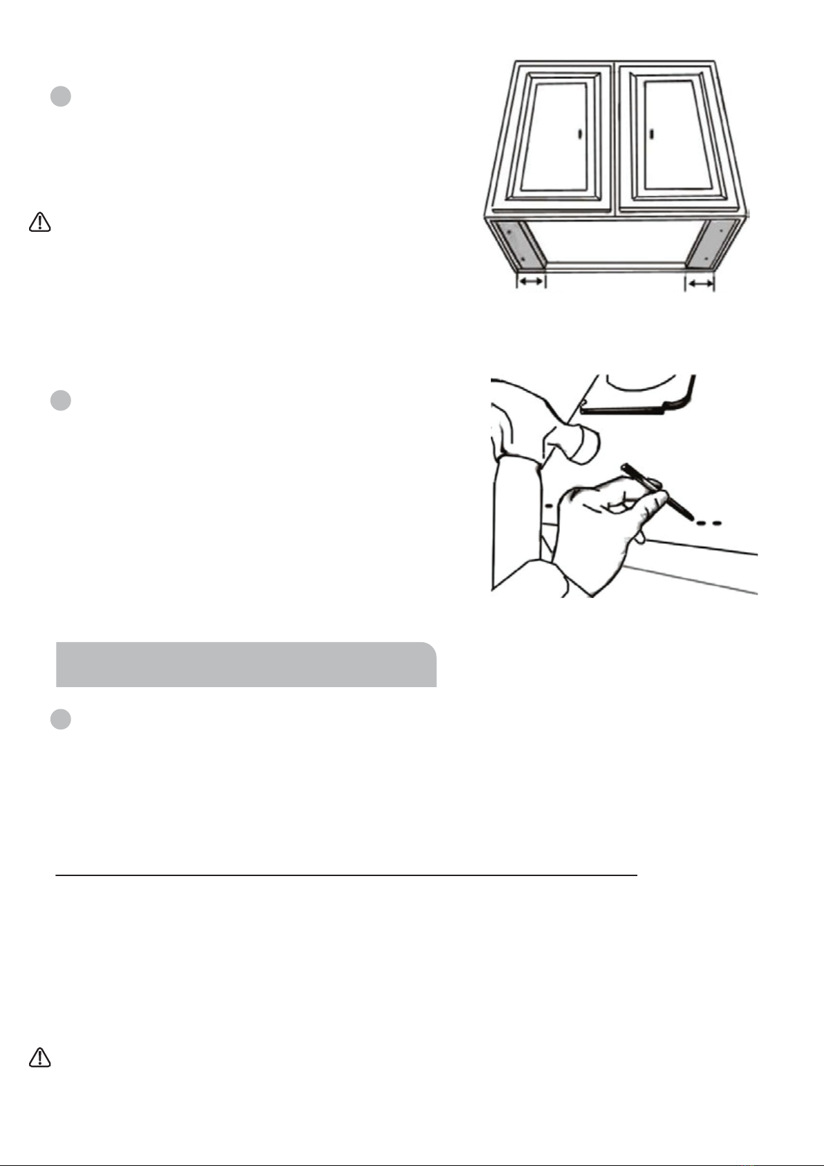
WARNING: This range hood is for under-cabinet installation ONLY.
• When cutting or drilling into walls or ceilings, be aware of electrical wires, piping, and
other utilities.
• To prevent back draft, sufficient air is needed for proper combustion.
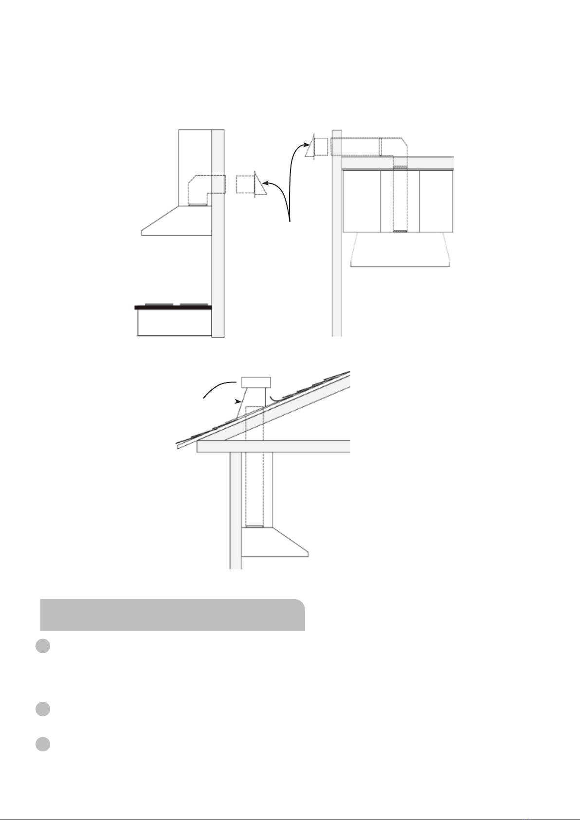
CAUTION: To reduce the risk of fire and to properly exhaust air, be sure to duct air out-
side - DO NOT vent exhaust air into attics, crawl spaces, garages, or within walls and ceil-
ings.
CAUTION: For general ventilation use only. Do not use to exhaust hazardous or explo-
sive materials and vapors.
• This appliance is intended for normal family household use only. It is not approved for out-
door use. Use of this product in a commercial setting or if installed outdoors will void the
warranty.
• Do not operate the range hood with a damaged cord or plug.
• Always have a working smoke detector near the kitchen.
• Have an appropriate fire extinguisher available, that is nearby, highly visible, and easily
accessible to the cooking appliance.
• Apart from hazardous grease fires, small food fires should be extinguished by smothering
with baking soda. Never use water on cooking fires.
• Whenever possible, do not operate the ventilation system during a cooktop fire. However,
do not reach through fire to turn it off.
WARNING: TO REDUCE THE RISK OF A COOKTOP GREASE FIRE, READ THE FOL-
LOWING:
• Use proper pan size. Always use cookware appropriate for the size of the surface ele-
ment.
• Never leave cooking elements unattended at high settings. Boil-overs can cause smoke
and grease to spill over that may ignite. Heat oils slowly on low or medium settings.
IMPORTANT SAFETY INSTRUCTIONS
2

• Always turn the hood ON when cooking at high heat or when flambéing food.
• Clean ventilation fans frequently. Grease should not be allowed to accumulate on the fan
or filters.
WARNING: TO REDUCE THE RISK OF INJURY, IN THE EVENT OF A COOKTOP
GREASE FIRE, READ THE FOLLOWING:
• SMOTHER FLAMES with a close-fitting lid, cookie sheet, or metal tray, then turn off the
burner. BE CAREFUL TO PREVENT BURNS. If the flames do not go out immediately,
EVACUATE AND CALL THE FIRE DEPARTMENT
• KEEP FLAMMABLE OR COMBUSTIBLE MATERIAL AWAY FROM FLAMES.
• NEVER PICK UP A FLAMING PAN - you may be burned.
• DO NOT USE WATER, including wet dishcloths or towels - a violent steam explosion will
result.
Use an extinguisher ONLY if:
a) You know you have a class A, B, C extinguisher and you already know how to operate it.
b) The fire is small and contained in the area where it started.
c) The fire department is being called.
d) You can fight the fire with your back to an exit.
• In the event of a gas leak, DO NOT turn on the range hood or any type of ventilator. Open
all doors and windows to disperse the gas.
• Before servicing or cleaning the unit, switch the power off, and lock the electrical panel.
This will prevent the power from accidentally turning on. If the electrical panel does not
lock, secure a warning label, such as a tag, to the electrical panel.
• The appliance is not intended to be used or cleaned by children or persons with reduced
physical, sensory, or mental capabilities or lack of experience and knowledge of the haz-
ards involved.
WARNING: Repairs should only be done by a trained servicer. Improper repair of your
appliance may result in risk of severe physical injury or death.
• The appliance is not intended to be used or cleaned by children or persons with reduced
physical, sensory, or mental capabilities or lack of experience and knowledge of the haz-
ards involved.
3

INSTALLATION REQUIREMENTS
PARTS SUPPLIED:
Power cord (attached
to the Range Hood)
Baffle Filter Spacer
Wall Anchor
Range Hood
• Unpack range hood and ensure all listed parts are in the box.
• It is recommended for the vent system to be installed before hood is installed.
• Before making cutouts, make sure there is proper clearance within the ceiling or walls for the
exhaust vent.
• It is recommended that a professional installer performs the range hood installation.
PRIOR TO INSTALLATION:
RHC-3092 (30in) x 1
RHC-3692 (36in) x 1
RHC-4892 (48in) x 1
RHC-3092 (30in) x 1
RHC-3692 (36in) x 1
RHC-4892 (48in) x 1
Wall Mounting
Bracket
RHC-3092 (30in) x 1
RHC-3692 (36in) x 1
RHC-4892 (48in) x 1
Mounting Bracket
Screw
(Flat Head M5x12)
RHC-3092 (30in) x 6
RHC-3692 (36in) x 6
RHC-4892 (48in) x 6
Grease Tray
RHC-3092 (30in) x 1
RHC-3692 (36in) x 1
RHC-4892 (48in) x 1
Remote Control
RHC-3092 (30in) x 1
RHC-3692 (36in) x 1
RHC-4892 (48in) x 1
NOTE: Any additional hardware provided may be used interchangeably based on your wall type.
RHC-4892 (48in) x 2
Stainless Steel
Baffle Filter
RHC-3092 (30in) x 2
RHC-3692 (36in) x 2
RHC-4892 (48in) x 3
RHC-3092 (30in) x 8
RHC-3692 (36in) x 8
RHC-4892 (48in) x 8
Wall Anchor Screw
& Gasket
RHC-3092 (30in) x 8
RHC-3692 (36in) x 8
RHC-4892 (48in) x 8
+ 1 small middle filter
4

Ceiling
Height
Under Cabinet
Range hood
36”
Counter
Top
Max: 36”
24” (610 mm) Min / 36” (914 mm) Max
Min: 24”
Range
Hood
Height
Cabinet
Height
Countertop/Stove
This range hood has been designed to be installed under-cabinet, above a stove/hob. Before start-
ing the installation, consideration should be given as to how the installation will be carried out,
ensuring adequate space and clearances above the stove/hob.
When installed, the range hood must be positioned at least 24in (61cm) and at most 36in
(91.4cm) above the cooktop. NOTE: minimum of 30in (76cm) is required for gas stove top.
If the exhaust pipe is too long or there are too many bends, please select a suitable position to
install the range hood to ensure the appliance can suck-in smoke efficiently.
• This range hood must be ventilated to the outdoors.
• Do not ventilate the range hood into an attic or other enclosed areas.
• Use only metal/aluminum ductwork. Rigid metal/aluminum vent is recommended. Always keep
the duct clean to ensure proper airflow.
• Calculate the following figures before installation:
1. Distance from the floor to the ceiling.
2. Distance between the floor to the countertop/stove.
3. Distance between the cooking surface to the range
hood (recommend* 24” to 36”).
NOTE: minimum of 30” is required for gas stove tops.
4. Height of hood and exhaust duct cover.
LOCATION REQUIREMENTS:
VENTILATION REQUIREMENTS:
Cabinet or
Single-piece
Chimney
(Optional)
Height & Clearance
5

• Minimum mount height between cook top to hood bottom should be no less than 24’’ for
electric cook tops or 30’’ for gas stove tops, and no higher than 30’’ for electric cook tops
or 36’’ for gas cook tops.
• It is important to install the hood at the proper mounting height. Hoods mounted too low could
result in heat damage or a fire hazard; while hoods mounted too high will be hard to reach and will
lose its performance and efficiency.
• It is recommended that the range hood be vented vertically through the roof through 8” (20.3 cm)
or bigger round metal/aluminum vent work.
• The size of the vent should be uniform.
• Use no more than three 90° elbows.
• Make sure there is a minimum of 24” (61 cm) of straight vent between the elbows if more than
one elbow is used.
• DO NOT install two elbows together.
• The length of the vent system and number of elbows should be kept to a minimum to provide
efficient performance.
• The vent system must have a damper. If the roof or wall cap has a damper, DO NOT use a
damper (if supplied) on top of the range hood.
• Use HVAC foil tape or duct tape to seal all joints in the vent system.
• Use caulking to seal exterior wall or roof opening around the cap.
• Due to different ceiling height configurations, recommended height may not be applicable.
Ensure there is availability of an electrical power socket to power the range hood before fixing to
the wall.
Observe all governing codes and ordinances. Ensure that the electrical installation is adequate
and in accordance with the National Electrical Codes, ANSI/NFPA 70 (latest edition), all local
codes, and ordinances.
- A 110120V, 60 Hz., AC only, fused electrical circuit is required.
FOR THE MOST EFFICIENT OPERATION:
ELECTRICAL REQUIREMENTS:
6

• This range hood is factory set for venting through the roof or wall.
• Vent work can terminate either through the roof or wall. To vent through a wall, a 90° elbow is
needed.
INSTALLATION INSTRUCTIONS
• It is recommended for the vent system to be installed before hood is installed.
• Before making cutouts, make sure there is proper clearance within the ceiling or walls for the
exhaust vent.
• Disconnect the power.
• A minimum of 8” round or 3-1/4 x 10” rectangular duct (both purchased separately) must be used
to maintain maximum airflow efficiency.
• Always use rigid type metal/aluminum ducts if available to maximize airflow when connecting to
provided duct.
• Place a thick, protective covering over the countertop, cook top or range to protect from damage
or dirt.
• Remove any hazardous objects around the area when installing.
NOTICE:
• NEVER exhaust air or terminate duct work into spaces between walls, crawl spaces, ceiling,
attics, or garages. All exhaust must be ducted to the outside.
• Use metal/aluminum duct work only.
• A minimum of 8” round or 3-1/4 x 10” rectangular duct (both purchased separately) must
be used to maintain maximum airflow efficiency.
IMPORTANT:
This installation is for mounting the product under wall cabinetry. Ensure your wall has the
proper support to hold the range hood weight (RHC-3092 30in - 48.4lbs / 22kg, RHC-3692
36in - 52.8lbs / 24kg, and RHC-4892 48in - 62.7lbs / 28.4kg). These instructions are general
guidelines; please consult your installation specialist regarding the best type of mounting
hardware and support system based on your wall construction. All wall-mounted range
hoods, if possible, should be installed and supported by studs behind the wall. In the event
studs are not in alignment with the wall mount mounting plate holes, a wooden cross sup-
port system will need to be retrofitted to your existing studs. All homes are different, and
installations will vary.
WARNING:
Excessive Weight. At least 2 people are required to move and install this range hood. Spinal
or other bodily injuries may occur if this warning is not observed.
PREPARE LOCATION:
VENTING METHODS:
7

Vertical
Roof Venting
Roof cap
Option 2:
Side wall cap
Horizontal
Wall Venting
Option 1:
1. Place the range hood on a flat, stable surface. Connect the power cord of the range hood to a
designated standard outlet, 110120V/60Hz, AC only and turn the range hood ON. Verify all oper-
ations of the range hood by referring to the Operating The Range Hood section of this manual,
then turn the Range Hood OFF and unplug from the power outlet.
2. Place all supplied parts and required hardware on a flat, stable surface and verify the existence
of all supplied parts listed on Page 4.
3. Remove the filters and filter spacers to reduce the weight for installation. Using the filter han-
dles, lift each filter slightly upwards towards the motor, then angle the filter downwards until it can
be removed from the hood frame.
ADVANCED PREPARATION:
• Fasten all connections with sheet metal screws and tape all joints with certified HVAC foil tape or
duct tape.
• Use caulking to seal exterior wall or roof opening around the cap.
8

CAUTION:
If moving the cooking range is necessary to
install the hood, ensure the power of an electric
range is turned OFF at the main electrical box.
SHUT OFF THE GAS BEFORE MOVING A GAS
RANGE.
4. For installing under the cabinet with recessed
bottom, it is recommended (but not necessary) to
attach 4-inch wide wood filler strips (not provided) on
each side.
5. When mounting under the cabinet, puncture the
knockout holes on the hood. When mounting on the
wall, fasten the Wall Mounting Bracket to the back of
the hood using hardware provided, or other hard-
ware appropriate for your wall construction type.
If necessary, attach two rubber panels with adhesive
tape to the rear corners of the range hood.
This will help reduce vibrations and shaking when in
operation.
1. Measure the distance between stove top and the bottom of range hood. A distance between 24”
to 30” is recommended. For gas stove tops, a minimum distance of 30’’ and maximum of 36’’ is
recommended.
Make sure the range hood is level and not tilted.
You may choose between TWO METHODS (A or B) to install the range hood:
A - Attach the Range Hood Directly to the Kitchen Wall Cabinet:
A-1. Using references in Height & Clearance on Page 5, center the hood beneath the cabinet and
align with the front of the cabinet.
A-2. Draw power cable through cabinet access opening and center the hood beneath the cabinet.
A-3. While the hood is being held in position, insert screws from the inside of the hood into the
center of each knockout hole located at the top panel of the range hood, and secure to the cabinet
bottom. Finish tightening all screws until secure. Be careful when using an electrical screwdriver,
damage to the range hood may occur.
CAUTION: Make certain the range hood is secure before releasing!
Skip Part B below and proceed to Step 2.
INSTALL THE RANGE HOOD:
4” WIDE 4” WIDE
9

WALL
B - Attach the Range Hood to the Wall Via Wall Mounting Bracket
B-1. Using references in Height & Clearance on Page 5, mark the leveling point of the hood. Using
the 2 top holes of the Wall Mounting Bracket (Part G) as a guide, insert two Wall Anchor Screws
(Part F) on the wall, leaving 1/8”space away from the wall. Mounting the hood on wall studs or lum-
bers is highly recommended.
B-2. Fasten the Wall Mounting Bracket (Part G) to the back of the hood with six Mounting Bracket
Screws (Part H)
B-3. Align hood-mounting bracket to the screws on the wall and hook the hood into place as shown
in Figure 3. Tighten screws to secure hood to the wall.
2. For safety purposes, pre-drilled mounting holes are provided through the back of the hood. For
a more secure installation, use as many mounting holes as needed to secure the unit from the
inside of hood.
3. Use a 8”diameter (size may vary) venting pipe (follow
building codes in your area) to connect the exhaust on
the hood to the ductwork above. Use HVAC foil tape /
duct tape to make all joints secure and airtight.
WARNING: Risk of electrical shock. This range hood
must be properly grounded. Make sure this is done
by a qualified electrician in accordance with all
applicable national and local electrical codes. Before
connecting wires, switch power off to prevent the
power from being switched on accidentally.
4. Connect the range hood to a designated standard outlet. If required, cut off the plug carefully
and connect three wires (black, white and green) to house wires and cap with wire connectors.
Connect according to colors (i.e. black to black, white to white, and green to green.)
5. Store excess wires in the wiring box.
6. Insert the Grease Tray into the
stainless steel frame of the range
hood, towards the rear. Push the
Grease Tray down until firmly in posi-
tion.
Figure 3Figure 2Figure 1
10

To install Baffle Filters:
A. Using the Filter Handles, tilt the
Baffle Filter so that it is angled
towards the back of the range hood
frame.
B. Raise the Baffle Filter upwards
until almost leveled.
C. Slide the Baffle Filter forward
slightly so that it sits into the recess
behind the front of the hood.
D. Lower the Baffle Filter.
E. Slide the Baffle Filter downwards
towards the wall until aligned with
the Filter Spacer.
NOTE: The Baffle Filters are
correctly inserted when positioned
at an approx 30° angle.
9. Turn power ON on the Control Panel. Check all lights and fan operation.
A
B
CD
E
8.
RHC-3092 (30in)
Two baffle filters
RHC-3692 (36in)
Two baffle filters
+ 1 small in between
RHC-4892 (48in)
Three baffle filters,
with two filter spacer
in between
7. NOTE: This step applies ONLY to 48in models: Install the Filter Spacers between Baffle
Filters as represented in the Baffle Filters Layout section below.
Baffle
Filters
Layout:
11

- To Turn the Fan ON press the Power Button and press the “+” button to increase the fan speed:
• Press “+” Once - Low (Digital Display shows F1)
• Press “+” Twice - Medium/Low (Digital Display shows F2)
• Press “+” Three Times - Medium/High (Digital Display shows F3)
• Press “+” Four Times - High (Digital Display shows F4)
- To Delay Power OFF Function - while the fan is in working mode, press the Timer Button once.
The digital display will blink, press “+” or “-” to increase or decrease delay time duration up to 15
min. The system will automatically shut-off after the chosen time passes.
- To Turn the Light ON/OFF press the Light On/Off button once.
NOTE: The fan and lights operate independently of each other.
- To Set the Time, press the Power button to turn On, and then press and hold the Timer Button
until Digital Display starts blinking.
The Hour part will blink (00:00)
Adjust the Hour by pressing the “+” for + hrs, or the “-” for - hrs. Once the Hour is correct, press the
Timer button to save and switch to the Minutes.
Set the minutes the same way (using the “+” and “-” buttons for + and - respectively).
Press the Timer button to save time setting.
- Remote Control Sensor:
The remote control sensor receives an infrared (IR) signal from the remote control. The maximum
distance for IR data transmission is 20 feet and requires direct line of sight. The transmission
distance may vary depending on temperature and the remote control battery condition.
Light settings are independent from other settings (including Power Off Delay) and lights have to
be manually turned On/Off.
Note: The Remote Control is powered by CR2025 battery.
00:00
RANGE HOOD USE
Remote
Control
Sensor
Lights
On/Off
Clock/
Timer
Digital
Display
Power
On/Off
Minus
Touch
Button
Plus
Touch
Button
RANGE HOOD CONTROLS:
OPERATING THE RANGE HOOD:
12

REMOTE CONTROL:
Power
On/Off
Lights
On/Off Sensor - selected
models only
Decrease
Fan Speed
Increase
Fan Speed
Timer
13

CLEANING & MAINTENANCE:
WARNING: To reduce the risk of electrical shock, DO NOT clean the hood while it's
operating.
WARNING: Never put your hands into the area housing the fan when the fan is
operating.
RANGE HOOD CARE
IMPORTANT: Clean the hood, grease tray, and baffle filters frequently according to the following
instructions.
The saturation of greasy residue in the exhaust vent and filters may cause increased inflammabili-
ty. Always keep the unit clean and free of grease and residue build-up to prevent possible fires.
DO NOT operate the Range Hood when filters are removed.
Exterior Surfaces:
To avoid damage to the exterior surface, do not use steel wool or soap-filled scouring pads.
Always wipe dry to avoid water marks.
Cleaning Method:
- Liquid detergent soap and water, or all-purpose cleaner.
- Wipe with a soft damp cloth or non-abrasive sponge, rinse with clean water, and wipe dry.
- For discolorations or deposits that persist, use a non-scratching household cleanser or stainless
steel polishing powder with a little water and a soft cloth.
- Do not allow deposits to remain for long periods of time.
Stainless Steel Baffle Filters, Grease Tray, Filter Spacers:
- Filters, grease tray, and filter spacers should be cleaned frequently (every two months of opera-
tion, or more frequently for heavy use).
1. Remove all the parts mentioned above from the hood and discard oil and residue.
2. Wash the filters, grease tray, and filter spacers in the dishwasher, or soak in hot or warm water
with dish detergent for half an hour, then wipe the filters clean. Repeat these steps until there's no
oil residue remains.
NOTE: Stainless steel baffle filters, filter spacers and grease tray are top rack dishwasher safe.
3. Let the filters dry thoroughly.
4. Reinstall the grease tray, filter spacers, and baffle filters.
Replacing the LED Light Bulbs:
CAUTION! Disconnect from the power source before servicing.
14

1. If the range hood does not operate after installation:
• Check if the range hood has been plugged in, make sure that all power has been turned back
on and all electrical wiring is properly connected.
• Swap out the light assembly to working ones to determine whether it is caused by defective
bulbs. (See Replacing the LED light bulb, page 13)
2. The range hood vibrates when the blower is on:
• The range hood might not have been secured properly to the cabinet or wall.
3. The blowers seems weak:
• Check that the duct sized used is at least 8” (20.3cm). Range hood WILL NOT function efficiently
with insufficient duct size.
• Check if duct is clogged or if damper unit is not opening properly. A tight mesh on a side wall
cap unit might also cause restriction to the air flow.
4. The lights work but the blower is not spinning at all, is stuck, or is rattling.
• The blower might be jammed or scraping the bottom due to shipping damage.
5. The hood is not venting out properly:
• Make sure the distance between the cook top and the bottom of the hood is within recommend-
ed* 24” to 36” range, with minimum 30” for gas stove top.
• Reduce the number of elbows and length of duct work. Check if all joints are properly connected,
sealed, and taped.
• Make sure the power is on high speed for heavy cooking.
TROUBLESHOOTING
ATTENTION: Wear gloves to protect against sharp edges.
1. Unplug the range hood, or turn off the breaker.
2. Use a soft tool to gently dislodge the bulb's rim from its position OR remove baffle filters and
push the bulb out from the inside of the unit.
3. Replace the bulb.
4. Push the lamp back into its place until secured.
5. Plug in the range hood, or turn on the breaker.
15

6
SPECIFICATIONS
Power: 120V/60Hz
Dimensions:
RHC-3092 - 29.3/4in x 22in x 10in
RHC-3692 - 35.3/4in x 22in x 10in
RHC-4892 - 47.3/4in x 22in x 10in
Weight:
RHC-3092 30in - 48.4lbs
RHC-3692 36in - 52.8lbs
RHC-4892 48in - 62.7lbs
Baffle Filter size:
RHC-3092 30in - 14in x 14.7in x 0.6in
RHC-3692 36in - 14in x 14.7in x 0.6in
RHC-4892 48in - 14in x 14.7in x 0.6in
16

17
Body Design Seamless Stainless Steel, Satin Finish
Power Rating 120V / 60Hz (USA & Canada standard)
General Input Power 266 (260W + 2x3W)
Motor Input Power 260 W (130W + 130W)
Ampere 3 A
Levels Of Speed Control 4 Levels
Number Of Motors 2 Motors
Motor Type Single Chamber Ultra Quiet
Fan Type Centrifugal Squirrel Cage
Control Type LCD Control with Remote
Filtration Type Stainless Steel Baffle Filter
Illumination 6W LED
Venting Size Top, 8 inches Round
Interference Protection Radio Frequency Interference Protected
SPECIFICATIONS:
RHC-3092 30in
Body Design Seamless Stainless Steel, Satin Finish
Power Rating 120V / 60Hz (USA & Canada standard)
General Input Power 266 (260W + 2x3W)
Motor Input Power 260 W (130W + 130W)
Ampere 3 A
Levels Of Speed Control 4 Levels
Number Of Motors 2 Motors
Motor Type Single Chamber Ultra Quiet
Fan Type Centrifugal Squirrel Cage
Control Type LCD Control with Remote
Filtration Type Stainless Steel Baffle Filter
Illumination 6W LED
Venting Size Top, 8 inches Round
Interference Protection Radio Frequency Interference Protected
SPECIFICATIONS:
RHC-3692 36in

Body Design Seamless Stainless Steel, Satin Finish
Power Rating 120V / 60Hz (USA & Canada standard)
General Input Power 269 (260W + 3x3W)
Motor Input Power 260 W (130W + 130W)
Ampere 3 A
Levels Of Speed Control 4 Levels
Number Of Motors 2 Motors
Motor Type Single Chamber Ultra Quiet
Fan Type Centrifugal Squirrel Cage
Control Type LCD Control with Remote
Filtration Type Stainless Steel Baffle Filter
Illumination 9W LED
Venting Size Top, 8 inches Round
Interference Protection Radio Frequency Interference Protected
SPECIFICATIONS:
RHC-4892 48in

SWEDEN
JANSKA USA
5175 Commerce Dr, Baldwin Park, CA
support@janskaus.com
If you are not happy with the product for any reason,
feedback or questions, and we will do our best to make
things right for you!
Your purchase comes with a 100%
satisfaction guarantee from Janska
This manual suits for next models
2
Table of contents
Other JANSKA Ventilation Hood manuals