Jas Audio GP-120 User manual

Green Power GP-120 Integrated Amplifier
Operating Instructions
ThankyouforpurchasingtheGreen Power GP-120IntegratedAmplifier.Youarenowinpossessionofanintegratedamplifierdesigned to give
you years of reliable use. Flexibility in design makes possible this state-of-art amplifier to work in conjunction with an external device as a
pre-amplifier or a power amplifier as desired. Functions and operation of the Green Power GP-120 are very simple. However, the
following notes are provided to explain all aspects of its design and use. If you need more assistance, it is always advisable to go back to
the supplying dealer for help. When service work is necessary, the amplifier should be returned to your dealer in the original packing
materialifpossible.
The Green Power GP-120 amplifier is designed to work properly in normal domestic operating conditions. However, the amplifier's
performance may be affected if sited near to a radio transmitter such as a mobile phone etc. Re-locating the amplifier or the radio
transmitterwillnormalizethe situation.
MAINS CONNECTION
After unpacking the Green Power GP-120 amplifier, please keep the packing material in a safe place
for possible future use. In the pack there is a separate mains cable suitable for connecting to the
mains supply in the country of use. The IEC socket end of the cableshould befirmly insertedintothe
connectorontherearpanelmarked"AC".
Remember - do not overload the mains wall socket with too many plugs or adaptors. The high quality
performance of the amplifier will be impaired if the electrical supply to it is in poor condition. The "AC"
connection is also fitted with a fuse, specifically suited to the supply voltage of the country of use. Should it be
necessary to replacethemainsfuse,ensure thatyou usethe oneequivalent to what given in the container,i.e.5
x20mmsize. Unscrew cap of the container to replace fuse. After change, replace cap and screw tight.
IEC socket
Fuse container
# 3Asurge resisting for 220-240V 50Hz AC,
# 6Asurge resisting for 110-120V 60Hz AC
POWERCONSUMPTION
It is appreciated by Hi-Fi enthusiasts that leaving equipment powered-up continuously can improve performance of an amplifier. GP-
120 amplifier features a capability of maximizing output at a minimal consumption of energy. However, improvement in
sound quality comes at the expense of power consumption from the mains which will not only cost more but will also reduce the working
life of the amplifier. We recommend that if the equipment is not beingused for an extended period of time, switch it off from themainsswitch
ontherearpanel. Normalperformancecanbeachievedinashortperiodoftime.
SET-UP
To obtain the best results, make sure that the Green Power GP-120 amplifier is placed on a stable shelf or Hi-Fi equipment rack. It is
important to allow adequate ventilation to the amplifier. As the amplifier itself dissipates less heat in operation, large sized heat
conducting fins are not installed. As usual, it will still necessary to place the amplifier on its own shelf or the top of other equipment to
allow for this so that the amplifier could perform at optimal condition. Always have the volume control set at minimum(counter-clockwise)
whenswitchingonandoff so as toavoidanysuddenloudnoises.
OPERATINGTHEGREEN POWER GP-120AMPLIFIER(QUICKSET-UP)
Diagram 1

2
The default ofGP-120 isan integrated amplifier from the factory,i.e.to make pre-amp and power amp connected by using a pair of jumpers
properly put in place (marked pre-out and main-in inside a box on the rear) . Simply connect signal cables to the amplifier, and speakers
with a pair of speaker cables, a basic set up is then completed (see Diagram 1). Users are reminded to switch off the amplifier whenever
connection with external devices or in basic set up so as to avoidanypops,clicksorotherunwantednoises.
INPUTCONNECTIONANDSWITCHING
Asall the line inputlevelsarethesame,itisnotnecessarytousethepreciseinputasdescribed. Youmay,forexample,plugaCDplayerinto
the Tape input and obtain exactly the same result and performance as the dedicated CD input. This also applies to signal input from PC
and MP3 via a piece of 3.5-RCA cable (see Diagram 1a).
Page 2 of 4
http://www.jas-audio.com
Diagram 1a
PRE/POWERCONNECTIONS
The pre-amp output and the power amp inputs are available through RCA sockets on the rear panel. This is
helpful if you wish to bi-amp the Green Power GP-120 or just to make use of the signal amplification circuit to
work with an external power amp.The defaultsetting fromthe factoryis both sets of RCA (pre out and main-in)
are connected by having a pair of jumpers put properly in place.However,whenusing anexternal device,such
as a sub-woofer or graphic equalizer etc. it may be necessary to separate the pre and power amps. To do this,
simply remove the jumpers and connected the RCA sockets indicated as pre-out with a pair of signal cables
to an external device. On the contrary, when the GP-120 is intended to be used as a power amp, connect
signal source from an external device to the RCAs indicated as “main in”.
Users are reminded to switch off the amplifier whenever connection with external devices or in a basic set up
so as to avoidanypops,clicksorotherunwantednoises.
N.B.Switchtheamplifieroffbeforemakinganychangesinordertoavoidanypops,clicksorotherunwantednoises.
LOUDSPEAKERCONNECTIONS
The loudspeakers should be connected to the terminals using a suitable pair of cables designed specifically for audio use. High grade, touch
proof, terminals on the rear panel allow for 4mm plugs or bare wire to be connected. Tighten the terminal fully after fitting the speaker wire.
Pleaseconsultyourdealerforadviceifyouareunsure.
It is very important to connect theloudspeakers to the loudspeaker terminals in the correct phase. Cables are normally polarized with a line or
a raised bump on the positive side. If one channel is not connected in the same fashion as the other, a severe loss of bass performance
and a spreadingofthestereoimagewillresult.
Important - Do NOT short the loudspeaker cables together when the other ends are still connected to the amplifier, as permanent damage
can result. If it is necessary to move or change the location of the loudspeakers, make sure that you first 'switch off' the amplifier from the
mains.
VOLUME
Volume push buttons are marked as upward and downward arrows and are situated onthe
right hand side of the selector button is used to alter the relative level of the sound output
from the amplifier. Alternatively, volume can be controlled by the remote.
Selector & Volume
push buttons

3
LEDINDICATORS
When the Green Power GP-120 amplifier is first switched on, the pilot lamp above the button
willglowgreen.
Page 3 of 4
http://www.jas-audio.com
LED on the right displays input source number (1 to 4) and volume level in dB numeric notations. At power on, GP-120 is by
default to show input source from 2; volume level is then set at minimum and is shown as -80dB. Pressing corresponding buttons
on the faceplate to change volume level and select input source as desired. Alternatively, adjustment and changes can be effected
by using the remote control.
PROTECTIONMODE
The Green Power GP-120 amplifier features a protection mechanism against shorting the speaker cables. The amp will then
become muted so as to avoid damage to the voice coil of the loudspeakers. When this occurs, switch the amplifier off at once. Check
speaker cable connections to make sure that plugs are not in contact with each other or shorting occurs. Never attempt to short plugs of
speaker cables when the other ends of the cables are connected to terminals when the amplifier is in operation or being switched on.
In the event of a failure of the amplifier, the output and/ or the mains supply should be disconnected. User may require to return the amp
tothedealerforservicing.
LED Display
Pleasecheckwiththedealerfirstforadvice.
REMOTECONTROL
The remote control RC-1 handset as shown on the left is designed to operate the JAS Green Power
GP-120 Integrated amplifier. It allows the user to operate the volume control, input mute and selection of
source input.
OP AMP REPLACEMENT
GP-120 features interchangeability of Op amp in its power amp circuitry. Installed with a piece of Philips NE5532 is of JFET in its internal
circuitry. GP-120 amplifier performs with adequate power to deliver dynamic sound, warm and details with a taste of “tube” amplification.
RC-1
Below is the procedure for changing Dual Op Amp:
1. unscrew to open the cover of the amplifier;
2. locate the socket on the PCB as shown in the picture;
3. remove OP Amp by wiggling it so as to lift up from the IC socket;
4. alight latch of OP Amp with that appears on the IC socket;
5. press the entire OP Amp with all pins straight down into the IC socket.
Below is the procedure for changing Single Op Amp:
1. unscrew to open the cover of the amplifier;
2. locate the sockets on the PCB as shown in the picture;
3. remove OP Amp by wiggling it so as to lift up from the IC socket;
4. alight latch of OP Amp with that appears on the IC socket;
5. press the entire single OP Amp with all pins straight down into the IC socket on one side;
6. do the same with another piece of single OP Amp into the other IC socket on the other side;
7. make sure that of pins of OP Amps are in contact with the sockets.
OP AMP REPLACEMENT
Suggested list of replacement Dual OP Amps:
1. AD827 --- characterized by crystal clear high frequency and bouncing bass, peak gain at 50MHz;
SR at 300V/μs;
2. EI2244 --- timbre tends to be neutral, energy inclined to the high frequency side;
3. OP249 --- a product of PMI, US; characterized by neutral and balanced sound, accurate in
sound reproduction;
4. OPA2604; --- a product of Burr Brown; renowned as one of the best in delivering warm and
smooth sound that would expect from tubes, exquisite and smooth timbre.
Suggested list of replacement Single OP Amps:
1. NE5534 --- a twin of NE5532; as there is less interference as what would occur in using the dual
OP Amp, sound is soft, warm with details, and it is musical;
2. OPA604 --- a product of Burr Brown, the single version of OPA2604, characterized by warm and
smooth sound; more richness in the mid-range.
SPECIFICATION
Measured at 230V or 115V
Power Output into 4Ω(both channels driven) at rated mains voltage > 120 Watts
Total Harmonic distortion (20 Hz to 20 kHz) < 0.1%
Input Impedance 47KΩ

4
Signal to Noise Ratio > 102 dB
Input socket type 3 pin IEC, grounded
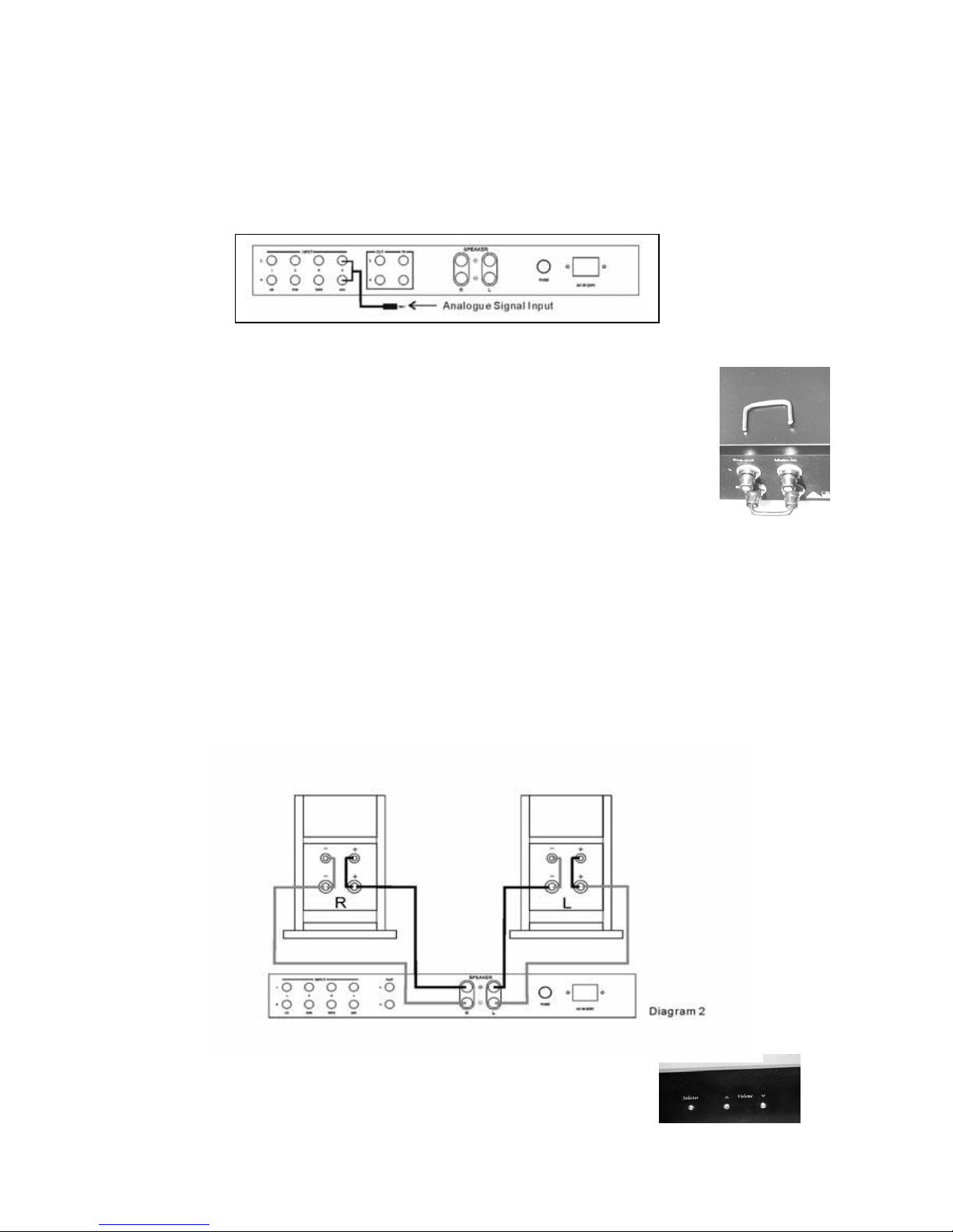
Loudspeaker outputs 2 pairs of terminals on rear
Mains voltage selector 115/230 V AC external Inputs
Input socket type (unbalanced) Gold plated RCA
Pre-amp output and power amp input connection Separate groups of RCA on rear
Weight (net) 12.5 Kgs
Size (W x D x H) mm 435 x 340 x 65 (mm)
Remote control RC-1 handset for controlling volume, mute and
Selection of sources
MAINS VOLTAGE AND FREQUENCY IS INTERNALLY SET FOR THE COUNTRY OF USE
JAS Audio reserves the right to change or modify the specification of its
products without prior notice or warning
WARRANTY
If within two years of purchase date your Green Power GP-120 amplifier proves to be defective for any reason other than
accident, misuse, neglect, unauthorized modification, or fair wear and tear, national distributor of JAS Audio will, at
its discretion, replace the faulty parts withoutchargeforlabor
Note: All JAS Audio amplifiers have their own serial number (S/N xxxxx), marked on the back of the chassis and also
rinted on the exterior of the packing box.p
TERMS AND CONDITIONS
1. The warranty is limited to the repair of the equipment. Neither transportation, nor any other costs, nor any
risk involved in removal, transportation and installation of products is covered by this warranty.
2. This warranty will not be applicable other than in case of defects in materials and/ or workmanship at the time of
purchase and will not be applicable:
a. for damages caused by incorrect installation, connection or packing,
b. for damages caused by any use than described in the user manual, or by negligence, or by
modifications, or by use of parts that are not made or authorized by JAS Audio,
c. for damages caused by faulty or unsuitable auxiliary equipments,
d. for damages caused by accident, lighting, water, fire heat, war, public disturbances or
any other cause beyond the reasonable control of JAS Audio and its appointed distributors,
e. for products whose serial number has been altered, deleted, removed or made illegible,
f. if repairs or modifications have been performed by an unauthorized person.
3. This guarantee complements any national/regional law obligations of dealers or national distributors and does
not affect your statutory rights as a customer.
How to claim repairs under warranty
Should service be required, please follow the following procedure:
1. If the equipment is being used in the country of purchase, you should contact the JAS Audio Authorized dealer
from whom the equipment was purchased.
2. If the equipment is being used outside the country of purchase, you should contact JAS Audio National
distributor in the country of residence for advice where the equipment can be serviced.
TO VALIDATE YOUR WARRANTY, YOU WILL NEED THE ORIGINAL SALES
INVOICE OR OTHER PROOF OF OWNERSHIP AND DATE OF PURCHASE
Version 1.1 and Copyright
©
November 2008 JAS AUDIO
Page 4 of 4
http://www.jas-audio.com
This manual suits for next models
1
Table of contents
Other Jas Audio Amplifier manuals