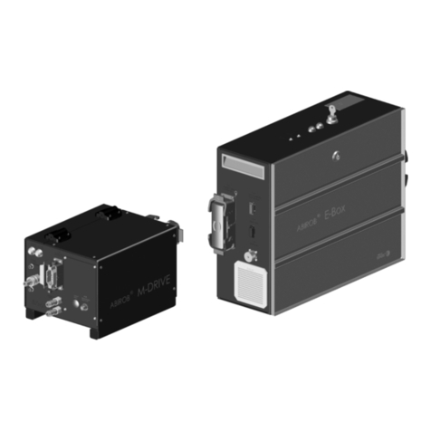
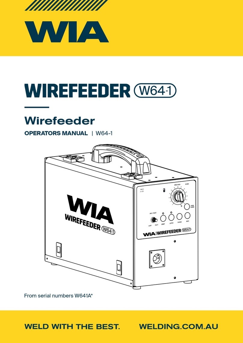
JAVAC NBM-500L User manual

Thank you for having purchased our product. Please read
instructions on use in this manual as well as the safety
rules given in the attached booklet and follow them care-
fully to get the best performance from the plant and be sure
that the parts have the longest service life possible. This
manual will show you the best way to do any maintenance
jobs or repairs eventually needed by your plant to resolve
any eventual problems, we do however recommend our
customers to arrange to have maintenance and eventual
repairs done at our servicing centers as they have the right
equipment and the highly qualified personnel is constantly
updated. All our machinery and systems are subject to con-
tinual development. We must therefore reserve the right to
modify their construction and properties.
The synergic multifunction NBM-500Lpower source, based
on the most modern IGBT based inverter technology with
digital control, allows high quality welding both in MIG/MAG,
and in Pulsed MIG on all materials and particularly on
stainless steel, aluminum and galvanized steel, by minimiz-
ing any reworking job after welding thanks to its spatter free
performance.
Technologically advanced, robust and easy-to-use,
NBM-500Lrepresents the ideal solution for any application
requiring high precision and repeatability of the achieved
results, by making this power source particularly suitable for
the most qualified jobs in any industrial application. The high
versatility of NBM-500Lalso achieves performances in
MMA welding.
The wire-feeder was designed for using all types of wire,
either solid or cored, and must only be used as part of the
welding generator and not for improper or any other use.
The general technical data of the system are summarized in
Table 1, Table 2and Table 3.
NBM-500L
The main feature of the welding unit NBM-500L are:
• Innovative and user friendly design;
• Metallic main structure with shockproof plastic front
frames;
• Robust handles built into the chassis;
• Control panel protected against accidental impact;
• Synergic digital control of all the welding parameters;
• BURN BACK control. At the end of each weld, in any con-
dition and with any material, the digital control ensures a
perfect wire cut, prevents the typical “wire globule” from
forming and ensures correct arc restriking;
• Spatter free exceptional welding characteristics in both
MIG/ MAG, MIG Pulsed and MIG Dual Pulsed on any
material and with any gas;
• High welding performance in MMA mode striking;
Table 1
Table 2
Table 3
Model
Cooling unit
Input voltage
V
380
Rated frequency
Hz
50-60
Power output
W
75
Capacity of tank
L
6
Maximum of flow
GPM
1.6
Maximum of pressure
PSI
60
• Wave form control. Both welding parameters and pulse
wave form, digitally controlled by the microprocessor, are
monitored and modified every few microseconds in order
to keep the arc constantly precise and stable by com-
pensating for continuous changes in welding conditions
caused by torch movement and workpiece irregularity;
• Ability to store personalized welding programs;
• Monitoring and repetition of welding parameters;
• User friendly and easy-to-use selection and recalling of
Model
NBM-500L
Three phase feeding
50/60 Hz
V380
Power supply: Zmax
ohm
(*)
Current range
MIG MAG
30-500 A / 16.5-40 V
ELECTRODE
30-500 A / 21.2-40 V
Installation power
kVA
25.1(MMA)/25.1(MIG)
Open circuit voltage
V
75-85V
Duty cycle at 100%
A
350
Duty cycle at 60%
A
500
Insulation class
F
Protection class
IP 21
Dimensions
mm
650*510*285
Weight
kg
28.6
Model
Wire Feeder
Input voltage of feeder
V
24
Power output of feeder
motor
W 84
N° rolls
4
Wire diameter
mm
0.8-1.6
Rated wire feeding
speed
m/min 2-21
Compatible wire types
•
Carbon steel
•
Stainless steel
•
Aluminium magnesium
•
Aluminium silicon
Protection gas
•
Carbon dioxide
•
Pure Argon
•
Argon-Carbon diox-
ide-Oxygen
•
Argon and Carbon dioxide
blends
Coolant
Maximum pressure
bar
Distilled water
3,5
Insulation class
F
Motor and control pro-
tection grade
IP 21
Dimensions
mm
375*370*285
Weight
kg
13.2
Introduction
Description
Technical data
Operating features

the parameters and welding programs;
• Low energy consumption;
• “Energy Saving” function to operate the power source
cooling fan and the torch water cooling only when neces-
sary;
• Auto-diagnostic feature for trouble shooting;
• Initial and crater welding cycle control;
Wire feeder
The main features of the wire feeder are:
• Welding current SYNERGIC adjustment;
• Arc length FINE adjustment;
• Wire test;
Cooling unit (optional)
• Water level monitoring;
The use of a welder is typically discontinuous, in that it is
made up of effective work periods (welding) and rest periods
(for the positioning of parts, the replacement of wire and
underflushing operations etc. This welder is dimensioned to
supply a I2 max nominal current in complete safety for a pe-
riod of work of 60% of the total usage time. The regulations
in force establish the total usage time to be 10 minutes. The
work cycle is considered to be 60% of this period of time. If
the permitted work cycle time is exceeded, an overheat
cut-off occurs to protect the components around the welder
from dangerous overheating. Messages flashing on the dis-
play will warn you when the heat safety device starts work-
ing (see paragraph “Alarm conditions”). After several
minutes the overheat cut-off rearms automatically and the
welder is ready for use again. Do not weld in the rain. This
generator is constructed in compliance with the IP23 protec-
tion level.
The system essentially consists of:
•
Weld unit;
•
Wire feeder unit;
•
Wire-feeder/generator interconnection cable;
•
Coolant unit for welding torch;
•
Trolley to carry it around;
Perform the following operations on receiving the apparatus:
•
Check that the welding apparatus is in good condition;
otherwise immediately inform the retailer or distributor;
•
Check that all the ventilation grilles are open and that
there are no objects obstructing the free flow of air.
Strap the system safely and securely in the slings working
from the bottom, then lift up from the ground.
NBM-500L
The welder has two handles to carry it around manually.
Wire feeder
The wire-feeder has a handle and a tray so that it can be
hung up.
NOTE: Do not use other equipment to lift or transport the
feeder.
The installation site for the system must be carefully chosen
in order to ensure its satisfactory and safe use. The user is
responsible for the installation and use of the system in ac-
cordance with the producer’s instructions contained in this
manual.
Before installing the system the user must take into consid-
eration the potential electromagnetic problems in the work
area.
In particular, we suggest that you should avoid installing the
system close to:
•
signaling, control and telephone cables;
•
radio and television transmitters and receivers;
•
computers and control and measurement instruments;
•
security and protection instruments.
Persons fitted with pace-makers, hearing aids and similar
equipment must consult their doctor before going near a
machine in operation. The equipment’s installation envi-
ronment must comply to the protection level of the frame.
The welding unit is characterized by the following classes:
• IP 21 protection class indicates that the generator can be
used in both interior and exterior environments;
This system is cooled by means of the forced circulation of
water.
Assemble the system in the following way:
•
Assemble the trolley;
•
Attach the welding unit to the trolley;
•
Assemble the wire-feeding unit onto the trolley;
•
Attach the coolant unit to the trolley and to the welder
(electrical and water connections).
•
Connect up the wire-feeder/generator interconnection ca-
ble;
•
Connect up the welding cables;
•
Connect up the welder to the mains.
Usage limits
Opening the packaging
How to lift up the system
Installation and connections
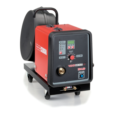
CONNECTING THE WIRE-FEEDER/GENERATOR INTERCONNECTION CABLE
This cable connects the welding machine to the wire-feeder.
WARNING: Do not disconnect the wire-feeder until the
machine has been switched off (see paragraph “Alarm con-
ditions”).
DIRECT-POLARITY welding
Connect up the interconnection cables (power cable, ancillary
wiring and gas tube) to the special attachments and couplings
shown in Figure 1.
The delivery and return water tubes, used for cooling the
torch of the welding machine, are part of the interconnection
cable and should be connected as follows:
interconnection cable on generator side: connect up air plug
and welding cable (positive) to their rapid couplings;
wire feeder side connecting cable: connect up air plug, air
pipe and welding cable (positive) to their rapid couplings
(Figure 1);
Figure 1

CONNECTION OF THE WELDING CABLES
Electrode welding (MMA)
With the machine disconnected from the supply, connect the
welding cables to the out terminals (positive and negative) of
the welder, connecting them to the gripper and the earth,
with the correct polarity provided for the type of electrode to
be used. Choosing the indications supplied by the electrode
manufacturer, the welding cables must be as short as pos-
sible, close to one other, and positioned at floor level or
close to it.
Figure 2
MIG-MAG / MIG PULSED / MIG DUAL PULSED welding
DIRECT-POLARITY welding
To start MIG-MAG welding, make the connections shown in
Figure 3, more precisely (with the machine switched off):
connect the generator - feeder connecting cable as shown in
Figure 3. Gas cylinders are supplied with a pressure reducer
to adjust pressure of the gas used for welding;
•
connect up the earthing system cable to the rapid coupling
marked by a - (negative) symbol and then the relevant
earth clamps to the piece being welded or to its support in
an area free from rust, paint and grease. Using particularly
long earthing cables reduces the voltage and causes
some problems from increased resistance and inductance
of the cables that could cause faulty welding. Follow in-
structions to avoid these problems:
-
use earthing and extension cables with appropriate sec-
tion;
-
lay out the cables as a flat as possible to prevent them
from coiling up.
•
screw the torch power cable to the centralized attachment
on the front panel of the wire-feeder and connect up the
delivery and return water tubes to their rapid couplings
located on the wire-feeder.
Figure 3

•
Open the side panel and fit the reel on the support so that
the wire unrolls clockwise, and center the projecting ref-
erence on the support with the relative hold on the reel.
•
Thread the end of the wire into the back guide (Pos. 1,
Figure 4) on the drawing mechanism.
•
Lift up the idle rolls (Pos. 8, Figure 4) releasing the roll
pressure device (Pos. 5, Figure 4). Make sure that the
drive rolls (Pos. 3, Figure 4) have the diameter corre-
sponding to the wire being used stamped on the outside.
•
Thread the wire into the central wire guide (Pos. 9, Figure
4) and into the wire guide of the centralized attachment
(Pos. 4,Figure 4) for a few centimetres. Lower the idle
roll-holder arm making sure the wire goes into the slot of
the drive roll. If necessary, adjust the pressure between
the rolls with the screw provided (Pos. 5, Figure 4). The
correct pressure is the minimum that does not allow the
rolls to skid on the wire. Excessive pressure will case de-
formation of the wire and tangling on the entrance of the
sheath; insufficient pressure can cause irregular welding.
Unscrew the two screws (Pos. 6, Figure 4) and lower the
safety guard of the gearing (Pos. 7, Figure 4). Lift up the idle
rollholder arm (Pos. 2, Figure 4) and proceed as follows:
•
Each roll shows the type of wire and diameter on the two
external sides.
•
Install the right rolls (Pos. 3, Figure 4) making sure the
groove is in the correct position for the diameter of the wire
being used.
•
Close up the gearing safety guard again.
Figure 4
Figure 5
Loading wire
Assembly of drive rolls

Figure 6
Figure 7
Pos. 1 Fast coupling reverse polarity.
Pos. 2 Fast coupling straight polarity.
Pos. 3 Communication interface.
Pos. 4 Power switch.
Pos. 5 Communication interface.
Pos. 6 Fast coupling straight polarity.
Pos. 7 AC36V output power.
Figure 8
Figure 9
Pos. 1 Current encoder knob.
Pos. 2 Voltage encoder knob.
Pos. 3 Wire feeding key.
Pos. 4 MIG-MAG welding torch.
Pos. 5 Water tube.
Pos. 6 Water tube.
Pos. 7 Water tube.
Pos. 8 Water tube.
Pos. 9 Gas tube.
Pos. 10 Communication interface.
Pos. 11 Straight polarity.
Command and control units NBM-500L
Command and control units wire feeder

Figure 10
Figure 11
Pos. 1 Water shortage light.
Pos. 2 Power indicator light.
Pos. 3 Power switch.
Pos. 4 Water tube.
Pos. 5 Water tube.
Command and control units wire feeder

Figure 12
Page switching key (Pos.1)
This key is used to switch pages among welding page、
welding mode page and program page;
More paras key (Pos.2)
This key is used to access more parameters page;
Memory key (Pos.3)
This key is used to access memory page;
Back key (Pos.4)
This key is used to access the last page;
Wire feeding test key (Pos.5)
While system operates in GMAW mode, this key is used to
test wire feeding function.
Gas test key (Pos.6)
While system operates in GMAW mode or TIG mode, this key
is used to test gas function.
ENCODER knob and ENCODER key (Pos.7)
ENCODER knob is used to change parameter values or
switch selected options. ENCODER key are equal to enter
key.
Control panel NBM-500L DUAL PULSED

WARNING: Before welding, check that the data on the
power source plate correspond to the supply voltage and
frequency.
•
Start up the welder by turning the switch on the back panel
to 1 (N.B.: the machine will display the last settings made
before it was switched off when it is turned on again);
•
Set the various units according to the chosen welding
process.
Figure 13
ELECTRODE WELDING (MMA)
For coated electrode welding with devices that can be
adjusted from the user’s “Arc Force” and “Hot Start”.
You can access this welding mode by adjusting the EN-
CODER knob to MMA and then pressing the EN-
CODER key.
Connect up the welding cables following description in para-
graph “Connecting up welding - ELECTRODE welding ca-
bles”.
Welding parameters
Table 3 shows the values of current to use with the respec-
tive electrodes for the welding of common steels and
low-grade alloys. These data have no absolute value and
are indicative data only. For a precise choice follow the in-
structions provided by the electrode manufacturer. The cur-
rent to be used depends on the welding positions and the
type of joint, and it increases according to the thickness and
dimensions of the part.
A fairly approximate indication of the average current to use
in the welding of electrodes for ordinary steel is given by the
following formula:
I = 50 × (Øe - 1 )
where:
I = intensity of the welding current Øe = electrode diameter
Example: for electrode diameter 4 mm
I = 50 × (4 -1 ) = 50 × 3 = 150A
The preset values of the welding current (adjustable
with ENCODER knob) and open-circuit voltage will be dis-
played on thescreen before weldingstarts.
The values of the welding current being used for weld-
ing and the welding voltage will appear on the displays
during the welding process.
Table 3
Special functions
NOTE: Press the More parameters key to access more pa-
rameters page.A brief description of parameters that could
be changed follows
• Hot start -i.e. overcurrent being supplied when the arc is
switched on. (Hot start - from 0 to 10 with an adjustment
interval at1).
• Arc force - Intensive arc drive force to prevent to be
stuck.
• Anti-stick - The switch of prevention to stick.
• VRD -The switch of voltage reduction safeguard.
MIG-MAG, MIG PULSED AND MIG DUAL PULSED WELD-
ING
Thefollowingjobsmustbe donebeforestarting to weld:
• Open the gas cylinder valve slowly and adjust thepressure
regulator to obtain about 1,3 - 1,7 bar;
• Work the gas check key and adjust the flow to between 14
and 20 l/min. according to the current being used for
welding;
• The welding machine is now ready to beused.
Manual welding mode (activated for MIG-MAG welding
process only)
Ø ELECTRODE
(mm)
ELECTRODE TYPE - Current adjustment field (A)
WELDING
THICKNESS
(mm)
6010
6011 6012 6013 6020 6027 7014
7015
7016 7018
7024
7028
1,6
-
20-40
20-40
-
-
-
-
-
-
≤5
2
-
25-60
25-60
-
-
-
-
-
-
2,4
40-80
35-85
45-90
-
-
80-125
65-110
70-100
100-145
≤ 6,5
3,2
75-125
80-140
80-130
100-150
125-185
110-160
100-150
115-165
140-190
> 3,5
4
110-170
110-190
105-180
130-190
160-240
150-210
140-200
150-220
180-250
> 6,5
4,8
140-215
140-240
150-230
175-250
210-300
200-275
180-255
200-275
230-305
> 9,5
5,6
170-250
200-320
310-300
225-310
250-350
260-340
240-320
260-340
275-365
6,4
210-320
250-400
250-350
275-375
300-420
330-415
300-390
315-400
335-430
8
275-425
300-500
320-430
340-450
375-475
390-500
375-475
375-470
400-525
> 13
Before welding
Welding procedures

Figure 14
Adjust the ENCODER knob and turn to GMAW Manual
then press the ENCODER key to access this weldingmode.
The programs available for MIG-MAG (see paragraph
“Synergic work procedures”) and adjustable parameters are
used as a basis for this welding procedure through the
ENCODER knob, which are not combined with each other
so that you are free to them as youwish.
Connectuptheweldingcables followingthedescription given
in paragraph “Connecting the welding - MIG-MAG, MIG
PULSED or MIG DUAL PULSED welding cables”.
Welding programs are displayed in the program table (see
special paragraph).
Use the ENCODER knob to select the program best suited
for the type of work to be done based on the knowledge of a
few parameters. (diameter of wire, material being welded,
type of gas to use)
The values of the preset welding current and the preset
welding voltage are displayed on the screen before
starting toweld.
Set as required and start welding.
The actual weld current and the actual weld voltage
will be displayed on the screen duringwelding.
The parameter on the displays remains unaltered when
changing from the setting to the welding phases and vice
versa.
Welding spot settings may also be created and memorized
withthisweldingprocedure(seespecialparagraphs).
SYNERGIC welding mode
Adjust the ENCODER knob and turn to GMAW Synergic,
GMAW Single or GMAW Dual then press the ENCODER key
to enter this welding mode.
Synergy is nothing else but a bond that unites the numerous
different sizes in the sense that when one of these sizes are
changed the others automatically change in synergy.
Set the welding current and welding voltage by adjusting the
panel on main engine or wire feeder. When setting the
welding current value, the value of wire feeding velocity
and material thickness will be dis-
played on the screen.
Connect up the welding cables following description given in
paragraph “Connecting the welding - MIG-MAG, MIG
PULSED or MIG DUAL PULSED welding cables”.
Use the ENCODER knob to select the program best suited
for the type of work to be done based on the knowledge of a
few parameters (diameter of wire, material being welded,
type of gas to use).
Theactualweldingcurrentand the actual welding voltage will
be displayed on the screen during welding.
The parameter on the display does not alter when changing
from the setting to the welding phases and vice versa.
Welding mode
Figure 15
When the machine operates in GMAW process, change
welding mode as follows:
•
Press the Page switching key to access welding mode
page;
•
Adjust the ENCODER knob to select welding mode wanted
then press the ENCODER key.
•
The welding mode will be displayed on the top left corner
of the screen.
Material program
Figure 16
When the machine operates in GMAW process, change
material program as follows:
•
Press the Page switching key to access material program
page;
•
Adjust the ENCODER knob to select material program
wanted then press the ENCODER key.
•
The welding mode will be displayed on the top center of
the screen.
Special functions
NOTE: Press the More parameters key to access more pa-
rameters page. A brief description of parameters that could
be changed follows and all the eventual combinations to be
had are summed up in table 5(easily legible).

Figure 17
1) Inductance - Make the arc soft or hard.
2) Gas pre-flow - Supplies a quantity of extra gas, for a
given time set in the factory, before starting to weld (from 0 to
3 seconds with a 0.1 seconds interval for adjustment);
3) Run in speed - Adjusts the starting speed of wire to the
piece. The given value is a variation against the values set
in the factory (from 0 to 10 with a 1 interval for adjustment);
4) Hot start - over current when ignition
5) Start current - in special 4T mode. The current of start
stage.
6) Start voltage - in special 4T mode. The voltage of start
stage.
7) End current - in 4T or special 4T. The current of end
stage.
8) End voltage - in 4T or special 4T. The voltage of end
stage.
9) Burn back - Adjusts the length of the wire coming out of
the gas nozzle after welding. The given value is a variation
against the values set in the factory. A higher number corre-
spondstogreaterwireburnback(from 0 to 10 with a 1 interval
for adjustment);
10) Gas post-flow - Supplies a quantity of extra gas, for a
given time set in the factory, before finishing welding (from 0
to 6 seconds with a 0.1 seconds interval for adjustment);
11) Spot time - Time needed for spot-welding (after press-
ing the torch key) after which the arc automatically switches
off (from 0.1 to 20 seconds with a 0.1 seconds interval for ad-
justment).
12) Dual frequency - Establishes the dual impulse fre-
quency (from 0 to 5 Hz with a 0.1 Hz interval for adjustment);
13) Dual dynamic - the dual pulse peak and base current
adjust. The percentage is -20% ~ 20%.
Table 5sums up the special programs available in the var-
ious welding modes and processes.
Figure 18
Establishing a new welding spot as follows:
•
Press the MEM key then enter the memory options
page;
•
Select the “Save” option and press the ENCODER key
then enter the memory channel page;
•
Select the channel in that the data will be saved and press
the ENCODER key.
NOTE: The creation of a GMAW welding point implies the
memorization of all the corresponding special functions.
Call up a welding spot as follows:
•
Press the MEM key then enter the memory options
page;
•
Select the “Load” option and press the ENCODER key
then enter the memory channel page;
•
Select the channel in that the data were saved and
press the ENCODER key.
Create and memorize new GMAW
welding
spots
Call up GMAW spots memorized beforehand

Table 5
PARAMETER
WELDING PROCESS
WELDING MODE
GMAW
Manual
GMAW
synergic
GMAW
Single
GMAW
Dual 2T 4T Spot Special 4T
Inductance
√
√
√
√
√
√
√
√
Gas pre
-flow √
√
√
√
√
√
√
√
Run in speed
√
√
√
√
√
√
√
√
Hot start
√
√
√
√
√
√
√
√
Start current
√
√
√
√
√
Start voltage
√√√√√
End current
√√√√√√
End voltage
√√√√√√
Burn back
√√√√√√√√
Gas post
-flow √
√
√
√
√
√
√
√
Spot time
√
√
√
√
√
Dual frequency
√
√
√
√
√
Dual dynamic
√
√
√
√
√

Figure 19
Resetfactoryvaluesas follows:
• Adjust the ENCODER knob and turn to “Settings” then
press the ENCODER key to access setting page.
• Adjust the ENCODER knob and select the “Factory reset”
option, then press the ENCODER key to reset the system.
NOTE: The special parameters of all the welding programs
are returned to their factory settings and the data in memory
are cleared.
Set time values as follows:
• Adjust the ENCODER knob and turn to “Settings” then
press the ENCODER key to access setting page.
• Adjust the ENCODER knob and select the “Date&Time”
option, then press the ENCODER key to set the date and
time.
Set control mode as follows:
• Adjust the ENCODER knob and turn to “Settings” then
press the ENCODER key to access setting page.
• Adjust the ENCODER knob and select the “Control mode”
option, then press the ENCODER key to set the Control
mode.
Panel mode - In this mode, set the welding current and
welding voltage by the panel of main engine;
Remote mode - In this mode, set the welding current and
welding voltage by the panel of wire feeder;
NBM-500L
WARNING: It is very important to remove all dust sucked
into the machine by the fans, as the welders are completely
electronic.
Proceed as described to keep the machine in good working
order:
•
Periodic removal of accumulated dirt and dust from the in-
side of the device, using compressed air. Do not aim the
air jet directly onto the electrical components, in order to
avoid damaging them.
•
Make periodical inspections in order to individuate worn ca-
bles or loose connections that are the cause of overheat-
ing.
TORCH
The torch is subjected to high temperatures and is also
stressed by traction and torsion. We recommend not to twist
thewireand not to use the torch to pull the welder.As a result
of the above the torch will require frequent maintenance
such as:
•
cleaning welding splashes from the gas diffuser so that the
gas flows freely;
•
substitution of the contact point when the hole is deformed;
•
cleaning of the wire guide liner using trichloroethylene or
specific solvents;
•
check of the insulation and connections of the power ca-
ble;
•
The connections must be in good electrical and mechan-
ical condition.
Alarm conditions found in the welder are described in this
paragraph and the screen on the operator’s interface used to
view them:
GENERAL FAILURE:
There is an inside fault. The machine needs to be restarted.
(Fig. 20)
Figure 20
OVER TEMPERATURE:
The temperature exceeds the limits. (Fig. 21)
Figure 21
Resetting
Date & Time
Control mode
Maintenance
Alarm conditions

STEP 1: Install the water tank
STEP 2: Install the main engine
STEP 3 Install the wire feeder
lnstallation illustration

STEP 4 Connect the tube and cable
Figure 22
In the Figure 22:
•
Pos.1, Pos.2, Pos.10, Pos.11 - Connect the water con-
necters in same colour with one water tube;
•
Pos.3 - Connect the gas connecter to gas cylinder;
•
Pos.4, Pos.7 - Connect the two communication interface
with communication cable;
•
Pos.5, Pos.8 - Connect the two straight polarity connect-
ers with one power cable;
•
Pos.6, Pos.9 - Connect the water tank power cable (Pos.9)
to the power socket (Pos.6);
Table of contents