1. Dolby Digital (AC-3) : 5.1 Dolby Digital technology outputs 6 independent audio
channels to the front left and right speakers, rear left and right speakers, center
speaker, and subwoofer.
2. dts : Another 5.1 Digital technology outputs 6 independent audio channels to the
front left and right speakers, rear left and right speakers, center speaker, and
subwoofer.
3. Dolby Surround Pro Logic : Dolby Surround Pro Logic technology outputs 4
independent channels to the front left and right speakers, rear speakers (single
channel), and center speaker. The low_bass or subwoofer channel is derived from
the front left and right speaker channels.
4. Stereo : Traditional 2-channel (left/right) analog audio.
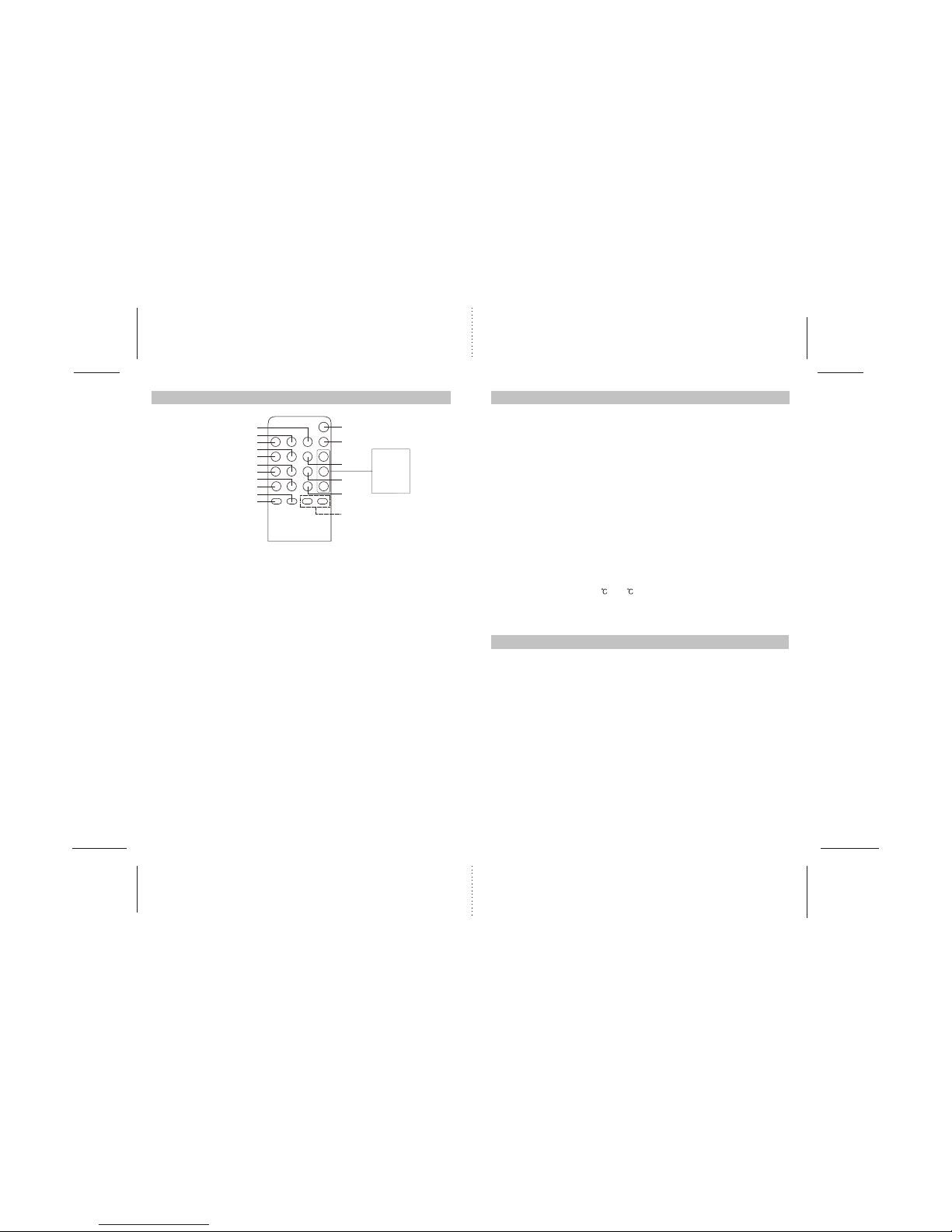
5. Mute : The mute function is used to quickly lower (or restore) the system volume.
6. Delay : Delay is a feature that allows the viewer to adjust the audio output delay of
the surround and center speakers. Doing this allows the viewer to hear sound from
the surround and front/center speakers simultaneously (without a delay). Because
the surround speakers are usually closer to the viewer than the front speakers,
Dolby Digital requires a split_second electronic delay of the surround channels.
This delay ensures that the viewer hears sound from the surround and front/center
speakers simultaneously.
7. Mode : Mode refers to which type of audio output technology is being outputted.
Choices are DTS(*) Dolby Digital, Dolby Pro Logic and Stereo.
8. Dynamic Range : The range between the loudest and softest sounds a system
can reproduce. This range may be adjusted by using the Dynamic function.
9. Test : The test mode is designed for use when Dolby Digital audio output is
selected. The test feature is used to individually test and balance the audio output
levels of each speaker. Unlike the "Trim" function (see below), the test function
uses a test signal.
10. Trim : Trim produces the same results as the "Test" function (see above) but uses
your audio input signal rather than a test signal from channel_to_channel.
11. SPCFG : Used on in the Dolby Digital and Dolby Pro Logic modes, the SPCFG
controls the amount of low_bass frequency to the front, center and rear speakers
when a subwoofer is not present. If a subwoofer is present, this feature is not
needed.
Glossary of Terms
5
6
Notice
1.Avoid exposing speakers to environments that are excessively warm and humid
(particularly in unventilated spaces or nearby heaters) or dusty.
2.Do not set speakers near windows exposed to direct sunlight or in areas prone to
water seepage.
3.Avoid excessive vibration of speakers.
4.Clean speaker housing by wiping with mild cleaning solution. Do not use solvents!
5.The speakers incorporate an efficient anti-magnetic architecture, permitting use in
close proximity to most television screens.If the use of your speakers cause
distortions in your television screen colors, try the following:
Turn off and unplug your television, turn on the speaker(s).After waiting 15 to 30
minutes, turn the television on and increase the distance between screen and
speakers until distortion disappears. Also, note whether other magnetic emission
sources are in the immediate vicinity. If so, relocate so as to prevent screen
distortion.
6. "!" WARNING : Before connecting or disconnecting any cables, make sure that
the speaker's power button is in the " OFF " position and the power adapter is
unplugged from the power source and not receiving power.
7.
Manufactured under license from Dolby Laboratories. " Dolby " , "Pro Logic " and
the double-D symbol are trademarks of Dolby Laboratories.
All other brand and product names are trademarks or registered trademarks of
their respective holders.
8.All specifications subject to change without prior notice.
9.
To return all adjustment settings to the factory defaults, turn off the main system
power and unplug the DC power adapter. After 10 seconds, plug in the DC adapter.
Default Settings
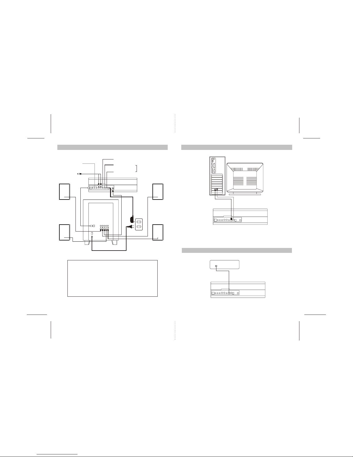
REAR
LEFT SPEAKER
REAR
RIGHT SPEAKER
FRONT
LEFT SPEAKER
FRONT
RIGHT SPEAKER
CENTER
SPEAKER
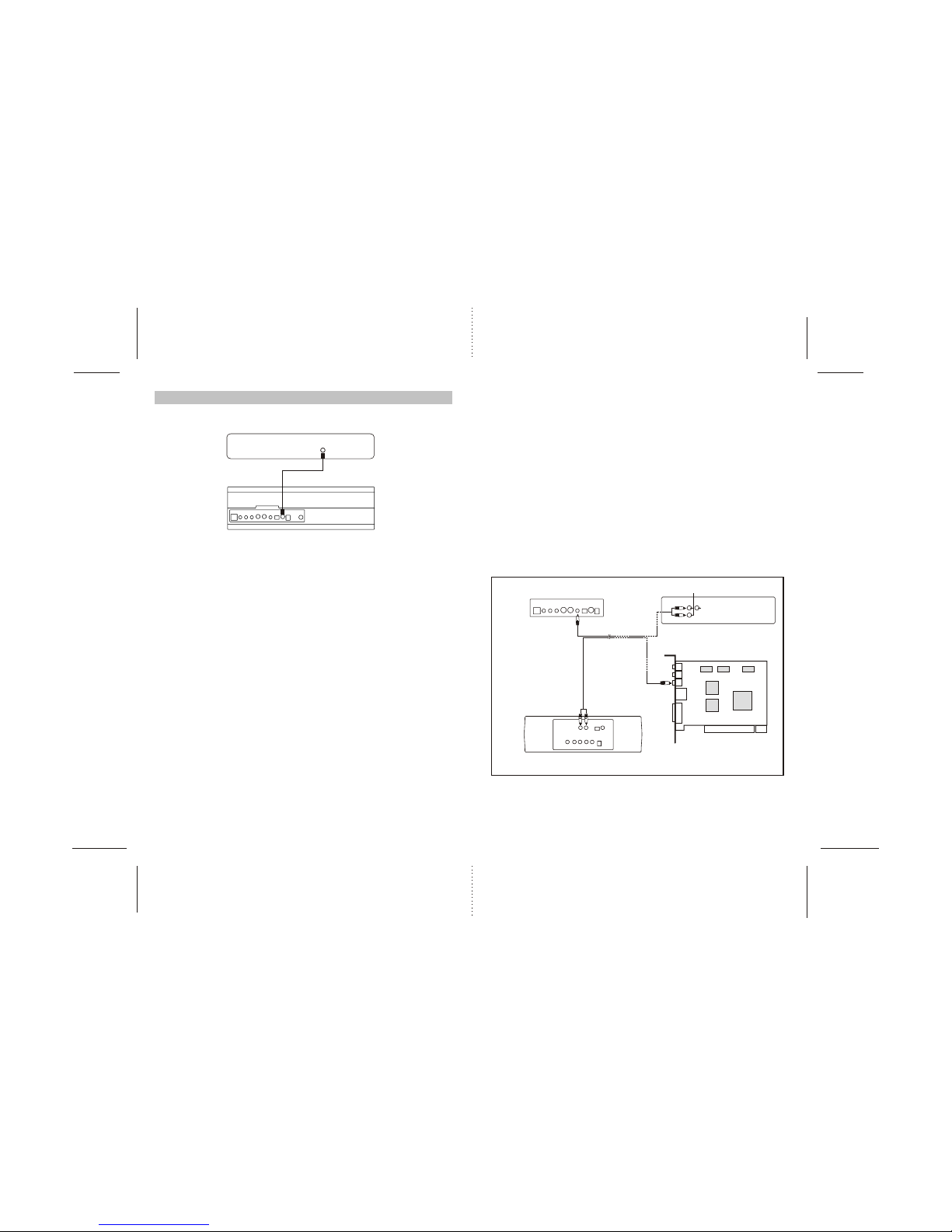
COMPUTER & AUDIO
DVD PLAYER
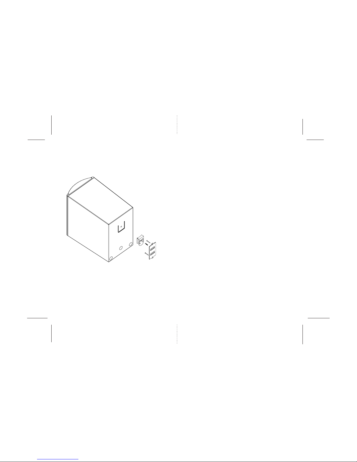
Fig(1)
SUBWOOFER
DECODER BOX