JBDC Plasma Cutter 20 A User manual

SOMMAIRE
TABLE OF CONTENTS
DESCRIPTION........................................................ 2 DESCRIPTION........................................................ 5
ALIMENTATION-MISE EN MARCHE ....................... 2 POWER SUPPLY – START UP ................................. 5
DÉCOUPAGE........................................................... 2 CUTTING................................................................ 5
FACTEURS DE MARCHE.......................................... 3 DUTY CYCLE........................................................... 6
ENTRETIEN ............................................................ 3 MAINTENANCE....................................................... 6
NOS CONSEILS ...................................................... 3 ADVICE .................................................................. 6
SÉCURITÉ .............................................................. 3 SECURITY .............................................................. 6
CONSOMMABLES ET ACCESSOIRES....................... 3 CONSUMABLES AND ACCESSORIES....................... 7
ANOMALIES CAUSES REMEDES ........................... 4 TROUBLESHOOTING .............................................. 7
GARANTIE.............................................................. 4 DECLARATION OF CONFORMITY ........................... 17
CERTIFICAT DE CONFORMITE...............................17 SPARE PARTS......................................................... 18
PIECES DE RECHANGE...........................................18 SYMBOLS ...............................................................18
ICONES ..................................................................18 FRONTAL SIDE.......................................................20
FACE AVANT...........................................................20
P : 8-10 / 17-20 P : 11-13/17-20 P : 14-20
V1
2
-
03
01
1
2
-
7
3502

2
DESCRIPTION
Merci de votre choix ! Afin de tirer le maximum de satisfaction de votre poste, veuillez lire avec attention ce qui suit :
Plasma cutter 20 A et cutter 30 A sont des découpeurs plasma nverter, portables, monophasés, ventilés. ls permettent
de découper en courant continu (DC) les aciers, les inox, aluminium, cuivre. ls fonctionnent sur une alimentation
électrique, monophasée 230V pour le Plasma cutter 20 A, monophasée comprise entre 85V et 265V pour le Plasma
cutter 30 A. ls sont protégés pour le fonctionnement sur groupes électrogènes.
ALIMENTATION ET MISE EN MARCHE
•
Ces appareils sont livrés avec une prise 16A de type CEE7/7.
Le plasma cutter 20 A doit être relié à une installation
électrique 230 V (50 - 60 Hz) AVEC terre pour le plasma cutter 20 A. Le plasma cutter 30 A dispose d’un système
« Flexible Voltage », il s’alimente sur une installation électrique AVEC terre comprise entre 110V et 240V (50 - 60
Hz). Le courant effectif absorbé ( 1eff) est indiqué sur l'appareil, pour les conditions d'utilisation maximales. Vérifier
que l'alimentation et ses protections (fusible et/ou disjoncteur) sont compatibles avec le courant nécessaire en
utilisation.
•Plasma 20A, la mise en marche s’effectue par l’appui sur l’interrupteur marche / arrêt. Plasma 30A, la mise en marche
s’effectue par rotation du potentiomètre sur la valeur de courant désiré (la mise en veille se fait sur la position "O" du
potentiomètre).
•L’appareil se met en protection si la tension d'alimentation est supérieure à 265V. Pour indiquer ce défaut, le voyant
jaune de protection thermique clignote 2 fois puis s’éteint. Le fonctionnement normal reprend une trentaine de
seconde après que la tension d'alimentation soit revenue dans sa plage nominale
•Ces appareils sont de Classe A. ls sont conçus pour un emploi dans un environnement industriel ou professionnel.
Dans un environnement différent, il peut être difficile d’assurer la compatibilité électromagnétique, à cause de
perturbations conduites aussi bien que rayonnées. Ne pas utiliser dans un environnement comportant des poussières
métalliques conductrices.
•
A partir du 1er décembre 2010, modification norme EN 60974-10 applicable pour le plasma cutter 20 A : Attention,
ces matériels ne respectent pas la CE 61000-3-12. S’ils sont destinés à être connectés au système public
d’alimentation basse tension, il est de la responsabilité de l’utilisateur de s’assurer qu’ils peuvent y être reliés.
Consulter si nécessaire l’opérateur de votre réseau de distribution électrique.
DÉCOUPAGE
•Raccorder l'appareil au réseau électrique et au réseau d'air (PLASMA cutter 30 A uniquement)
•Régler le régulateur de pression afin d'afficher 2.5 à 4 bar pour le plasma cutter 20 A et 2,5 à 6 bar sur le
manomètre pour le plasma cutter 30 A.
•Allumer l'appareil
Plasma Cutter 20 A : Au-delà de 1500m d’altitude la pression atmosphérique est insuffisante pour
permettre le fonctionnement du compresseur intégré.
Pour le plasma cutter 30 A : A partir de 10 A* et afin d’optimiser les performances de découpe, utiliser le
« testeur de débit d’air » fourni avec l’appareil. Pour cela :
-Appuyez sur la gâchette de votre torche (l’arc s’établit).
-Relacher, l’arc électrique se coupe mais l’air continue de s’écouler pendant environ 15 secondes.
-Pendant cette période, placer votre « testeur de débit d’air » à l’extrémité de votre torche, puis
ajuster votre débit d’air afin que la bille se situe dans la zone mini/maxi.
*nb : Pour une découpe < 10A, se régler directement à 3 bars.
•Régler le courant en fonction du type et de l'épaisseur de métal à découper.
Plasma cutter 20 A Plasma cutter 30 A
Epaisseur
(mm) Courant
(A) Vitesse
(m/min) Courant
(A) Vitesse
(m/min)
0,6 5 4,1 5 4,1
1 12 2,5 12 2,5
1,5 15 1,2 15 1,2
2,5 18 0,65 18 0,65
3 20 0,35 20 0,35
4 20 0,26 20 0,26
6 20 0,15 25 0,20
8 - - 30A 0,16
Acier
10 - - 30 0,09
0,6 8 2,5 8 2,5
1 12 1,2 12 1,2
1,6 15 0,65 15 0,65
2,5 20 0,25 20 0,25
4 20 0,15 25 0,21
6 - - 30 0,23
Aluminium
8 - - 30 0,09

3
•Relier la pince de masse sur une zone décappée de la pièce à découper
•Le découpeur PLASMA est muni d'un système d'arc pilote permettant d'amorcer l’arc sans avoir besoin de toucher la
pièce à découper. La découpe peut donc s'effectuer de deux manières :
▪ Appui sur gâchette formation de l'arc pilote découpe en venant au contact de la pièce
▪ Contact avec la pièce appui sur gâchette découpe immédiate
•Pendant la découpe assurez-vous de bien maintenir le contact entre la tuyère et la pièce à découper
FACTEURS DE MARCHE
•Les postes décrits ont une caractéristique de sortie de type "courant constant". Leurs facteurs de marche selon la
norme EN60974-1 sont indiqués dans le tableau suivant :
X / 60974-1 @ 40°C
(T cycle = 10 min)
Plasma
cutter
20 A
Plasma
cutter
30 A
(230V)
Plasma
cutter
30 A
(110V)
max 26% @ 20 A 32% à 30A 25% à 30A
60% (T cycle = 10 min) 12 A 22 A 19 A
100% (Tcycle = 10 min) 11 A 18 A 15 A
Note : les essais d’échauffement ont été effectués à température ambiante et le facteur de marche à 40 °C a été
déterminé par simulation.
ENTRETIEN
•L'entretien ne doit être effectué que par une personne qualifiée.
•Couper l'alimentation en débranchant la prise, et attendre l’arrêt du ventilateur avant de travailler sur l'appareil. A
l’intérieur, les tensions et intensités sont élevées et dangereuses.
•l est conseillé 2 à 3 fois par an d’enlever le capot et dépoussiérer à la soufflette. En profiter pour faire vérifier la
tenue des connexions électriques avec un outil isolé par un personnel qualifié.
•Contrôler régulièrement l'état du cordon d'alimentation. Si le câble d'alimentation est endommagé, il doit être
remplacé par le fabricant, son service après vente ou une personne de qualification similaire, afin d'éviter un danger
NOS CONSEILS
•Laisser les ouïes de l'appareil libres pour l’entrée et la sortie d’air.
SÉCURITÉ
Le découpage peut être dangereux et causer des blessures graves voire mortelles. Protégez vous et
protégez les autres.
Respecter les instructions de sécurité suivantes
:
Rayonnements Protéger vous à l’aide d’un masque muni de filtres conformes EN 169 ou EN 379.
de l’arc :
Pluie vapeur d’eau Utiliser votre poste dans une atmosphère propre (degré de pollution ≤ 3), à plat
humidité: et à plus d’un mètre de la pièce à découper. Ne pas utiliser sous la pluie ou la neige.
Choc électrique : Cet appareil ne doit être utilisé que sur une alimentation monophasée à 3 fils avec neutre relié
à la terre. Ne pas toucher les pièces sous tension.
Vérifier que le réseau d'alimentation est adapté au poste.
Chutes : Ne pas faire transiter le poste au-dessus de personnes ou d’objets.
Brûlures : Porter des vêtements de travail en tissu ignifugé (coton, bleu ou jeans).
Travailler avec des gants de protection et un tablier ignifugé.
Protéger les autres en installant des paravents ininflammables, ou les prévenir de ne pas
regarder l'arc et garder des distances suffisantes.
Risques de feu : Supprimer tous les produits inflammables de l'espace de travail. Ne pas travailler en présence
de gaz inflammable.
Fumées : Ne pas inhaler les gaz et fumées de soudage. Utiliser dans un environnement correctement
ventilé, avec extraction artificielle si découpage en intérieur.
Précautions Toute opération de découpage :
supplémentaires : - dans des lieux comportant des risques accrus de choc électrique,
- dans des lieux fermés,
- en présence de matériau inflammable ou comportant des risques d'explosion,
doit toujours être soumise à l'approbation préalable d'un "responsable expert", et effectuée en
présence de personnes formées pour intervenir en cas d'urgence.
Les moyens techniques de protections décrits dans la Spécification Technique CE / EC 62081
doivent être appliqués.
Le découpage en position surélevée est interdit, sauf en cas d'utilisation de plates-formes de
sécurité.
Les porteurs de stimulateurs cardiaques doivent consulter un médecin avant d'utiliser ces appareils.

4
CONSOMMABLES ET ACCESSOIRES
Consommables
Vérifier régulièrement l’état d’usure de la buse de protection, de la tuyère et de l’électrode ou en cas de réduction
significative de la vitesse de découpage.
l est conseillé de remplacer en même temps la tuyère et l’électrode.
Buse (ref.040209 : plasma cutter 20 A / ref.040236 : plasma cutter 30 A)
Remplacer si fissurée ou endommagée
Tuyère (ref.040151 plasma cutter 20 A / ref.040212 : plasma cutter 30 A)
Nettoyer si l’intérieur de la tuyère est obstrué ou sale
Remplacer si l’ouverture est déformée ou si la taille de l’orifice a augmenté de moitié.
Diffuseur (ref.040175 : plasma cutter 20 A ou cutter 30 A)
Remplacer si les orifices latéraux sont obstruées.
Électrode (ref.040168: plasma cutter 20 A ou cutter 30 A)
A remplacer : si une cavité importante apparaît en son centre.
Accessoires
ANOMALIES CAUSES REMEDES
Anomalies Causes Remèdes
L’appareil ne délivre pas de puissance.
Le vert de fonctionnement est allumé Le
voyant de protection thermique est allumé en
continu.
La protection thermique du
poste s’est déclenchée. Attendre la fin de la période de
refroidissement.
L’appareil ne délivre pas de puissance.
Le vert de fonctionnement est allumé
Le voyant de protection thermique clignote 2
fois puis s’éteint.
La tension d’alimentation
depasse 230V + 15% pour le
plasma cutter 20 A, 85 V -
265V pour le plasma cutter
30A.
Vérifier votre installation électrique ou
votre groupe, puis éteindre et rallumer
votre appareil.
Défaut torche. Vérifier que votre torche soit bien
montée, puis éteindre et rallumer votre
appareil.
L’appareil ne délivre pas de puissance.
Le vert de fonctionnement est allumé
Le voyant de protection thermique clignote
rapidement. Alimentation d’air trop faible. Augmenter la pression d’air puis éteindre
et rallumer votre appareil
En appuyant sur la gachette, de l’air s’écoule
mais l’arc pilote ne fonctionne pas. Consommables usés Vérifer et changer les consommables.
L’arc électrique se coupe au bout de 3
secondes environ. Problème de masse Vérifier que la pince de masse soit bien
reliée à une partie propre (non grasse et
non peinte) de la pièce à découper
Le poste est alimenté, vous ressentez des
picotements en posant la main sur la
carrosserie.
la mise à la terre est
défectueuse. Contrôler la prise et la terre de votre
installation.
Plasma cutter 30 A : Après avoir éteint le
plasma (position "O"), le ventillateur et l’air
comprimé continue à fonctionnner.
Phase de refroidissement de la
torche
Comportement normal du poste,
attendre la fin de la phase de
refroidissement (+/-15 sec)
CONDITIONS DE GARANTIE FRANCE
La garantie couvre tout défaut ou vice de fabrication pendant 1 an, à compter de la date d’achat (pièces et main
d’œuvre). La garantie ne couvre pas les erreurs de tension, incidents dus à un mauvais usage, chute, démontage ou
toute autre avarie due au transport.
La garantie ne couvre pas l’usure normale des pièces (Ex. : câbles, pinces, etc.).
En cas de panne, retournez l’appareil à votre distributeur (port dû refusé), en y joignant :
- Un justificatif d’achat datée (ticket de caisse ou facture).
- Une note explicative de la panne.
Après la garantie, notre SAV assure les réparations après acceptation d’un devis.
Kit compas (ref. 040205)
Pour découpe circulaire
jusqu’à 134 cm diamètre.
Fourni avec 3 axes :
aimanté, à pointeau,
à visser
Chariot (
Ref. 040199)
Pour un confort d’utilisation
et être à distance recommandée
afin d’optimiser les performances
de découpe et améliorer la durée
de vie des tuyères.

5
DESCRIPTION
Thank you for choosing our product! To get the best of your equipment, please read carefully the following.
Plasma Cutter 20 A and cutter 30 A are inverter plasma cutters, portable, single phase, ventilated. They enable to cut in
direct current (DC) steel, stainless steel, aluminium, copper. They work with a single phase 230V input for the plasma
cutter 20 A, a single phase input spread between 85V to 265V for the plasma cutter 30 A They are over-voltage
protected when used on power generators
POWER SUPPLY – START UP
•This machine is delivered with a 16A plug type EEC7/7. The Plasma cutter 20 A must be plugged on a 230 V (50-
60Hz) socket with earth. The plasma cutter 30 A integrates a « Flexible Voltage » system. t has to be on a power
suply variable between 85V and 265V (50 – 60 Hz) WITH earth. The absorbed effective current ( 1eff) is shown on
the machine, for maximal using conditions.
Check that the main supply and its protections (fuse and/or circuit breaker) are compatible with the required current
in use.
•To start the equipment, turn on the potentiometer to the desired current position (put the potentiometer on "O" for
standby mode).
•The machines are protected against overvoltages and pass automatically in standby mode if the supply voltage
exceeds 265V. To point out this defect, the yellow indicator for thermal protection blinks twice then lights off. Normal
operation will resume after thirty seconds when the voltage has returned to its nominal range.
•This appliance is dedicated for use in industrial environment according to C SPR 11. n a different environment, it can
be difficult to insure the electromagnetic compatibility. Do not use in an environment containing metallic dust
particles which may conduct electricity.
•These are A-class devices. They are designed to be used in an industrial or professional environment. n a different
environment, it can be difficult to ensure electromagnetic compatibility, due to conducted disturbances as well as
radiation.
•From 1st December 2010, the new standard EN 60974-10 will be applicable for plasma cutter 20 A: Warning: these
materials do not comply with EC 61000-3-12. f they are to be connected to a low-voltage mains supply, it is the
responsibility of the user to ensure they can be connected. f necessary consult the operator of your electrical
distribution system.
CUTTING
•Connect the unit to the electricity network and to the air distribution (PLASMA cutter 30 A only)
•Adjust the pressure regulator in order to have 2.5 to 4 bar for Plasma Cutter 20 A or 2,5 to 6 bar for Plasma cutter 30
A on the manometer.
•Switch on the unit.
Plasma cutter 20 A : Above an altitude of 1500m the atmospheric pressure will be insufficient to operate
the integrated air compressor.
For the plasma cutter 30 A : From 10 A* and to optimize the cutting performances, use the « air flow
tester » supplied with the machine. Process :
-Press the torch trigger (the arc is appearing).
-Release, the electrical arc stops but the air continues to flow for about 15 seconds.
-During this time, put your « air flow tester » at the end of your torch, then adjust your air flow by
placing the ball inbetween the mini/maxi zone.
*nb : For a cutting < 10A, directly adjust to 3 bars.
•Adjust the current according to the type of metal and the thickness to cut.
Plasma Cutter 20 A Plasma cutter 30 A
Thickness
(mm) Current
(A)
Speed
(m/min)
Current
(A)
Speed
(m/min)
0,6 5 4,1 5 4,1
1 12 2,5 12 2,5
1,5 15 1,2 15 1,2
2,5 18 0,65 18 0,65
3 20 0,35 20 0,35
4 20 0,26 20 0,26
6 20 0,15 25 0,20
8 - - 30A 0,16
Steel
10 - - 30 0,09

6
0,6 8 2,5 8 2,5
1 12 1,2 12 1,2
1,6 15 0,65 15 0,65
2,5 20 0,25 20 0,25
4 20 0,15 25 0,21
6 - - 30 0,23
Aluminium
8 - - 30 0,09
•Connect the earth clamp on a stripped zone of the piece to cut.
•The PLASMA cutting machine is equipped with pilot arc system. This system allows starting the arc without touching
the piece to cut. You have 2 ways to cut your piece :
▪ Press on the trigger pilot arc formation cutting by contact with the piece.
▪ Contact with the piece press on the trigger immediate cutting
•During the cutting, make sure to maintain the contact between the nozzle and the piece to cut.
DUTY CYCLE
The machines described have an output characteristic of 'constant current' type. The duty cycle are indicated in the
table below according to EN60974-1 Norm.
X / 60974-1 @ 40°C
(T cycle = 10 min)
Plasma
Cutter 20 A
Plasma
cutter
30 A
(230V)
Plasma
cutter
30 A
(110V)
max 26% @ 20 A 32% à 30A 25% à 30A
60% (T cycle = 10 min) 12 A 22 A 19 A
100% (Tcycle = 10 min) 11 A 18 A 15 A
Note: the running hot tests have been carried out at atmosphere temperature and duty cycle has been determined at
40°C by simulation.
MAINTENANCE
•Refer all servicing to qualified personnel.
•Disconnect the generator and wait until the ventilator stopped before working on the unit. nside the device,
voltages and current are dangerous.
•We suggest removing the steel cover 2 or 3 times a year and remove any excess dust. Let check the electrical
connections (with an insulated tool) and the insulations by qualified personnel.
•Regularly control the state of the cord. f this supply cable is damaged, it must be replaced by the manufacturer,
its after sales service or a similarly qualified technician to avoid any danger.
ADVICE
•Leave the inlets free to allow in/out air circulation.
SECURITY
Cutting can be dangerous and lead to serious or even fatal injuries. Protect yourself and protect the
others.
Respect the following warnings:
Arc rays : Protect yourself thanks to a welding helmet in compliance with EN175 equiped with filters in
compliance with EN 169 or EN 379. nform and protect by the same means any people in the
welding environment.
Rain steam The working environment must be clean (degree of pollution ≤ 3) and protected
humidity : against rain. Put the appliance on an even place and at least at one meter from the parts to
be cut. Do not use them under rain or snow.
Electric shocks : This appliance may only be use with a 230V monophase supply and must be earthed.
Moving : Do not underestimate the weight of the apparatus. Do not carry it over people or things. Do
not drop it. Do not set it brutally
Burns : Wear protective or fire-proof clothing (overalls, jeans).
Use some welder gloves and a fire-proof apron.
Protect the others by installing non flammable protection wall, or prevent the
others from looking at the arc and make them keep a sufficient distance
Fire risks: Suppress all flammable products from the working area. Do not work near flammable gas.
Smokes: Do not inhale gas or welding smokes. f indoors ventilate the area well and/or use local
extraction ventilation equipment to remove fumes and gases.
Extraprecautions: Any cutting operation:
- in environments with increased risk of electric shock,

7
- in confined spaces,
- in the presence of flammable or explosive materials
must be evaluated in advance by an “Expert supervisor” and must always be carried out in the
presence of other people trained to intervene in case of emergency.
Technical protection measures MUST BE taken as described in the TECHN CAL
SPEC F CAT ON " EC 62081".
Cutting in raised positions is forbidden unless safety platforms are used.
The persons carrying pacemaker have to consult a doctor before using these machines.
ACCESSORIES AND CONSUMABLES
Accessories
Consumables
Regularly check the wear condition of the protective tip, nozzle and electrode or in case of significant reduce of the
cutting speed.
t is advised to replace at the same time the nozzle and the electrode.
Tip (ref. 040182 : plasma cutter 20 A / ref.040236 : plasma cutter 30 A)
Replace if cracked or damaged.
Nozzle (ref.040151 plasma cutter 20 A / ref.040212 : plasma cutter 30 A)
Clean if the inside of the nozzle is blocked or dirty.
Replace if the opening is deformed or if the size of the orifice has half increased.
Diffuser (ref.040175 : plasma cutter 20 A or cutter 30 A)
Replace if lateral orifices are bolcked.
Electrode (ref.040168: plasma cutter 20 A or cutter 30 A)
To replace: if a significant cavity appears at the electrode center.
TROUBLESHOOTING
Anomalies Causes Remedies
The machine delivers no power.
The green working indicator is on.
The thermal protection indicator is
continuously on.
The thermal protection of
the welding unit is on. Wait until the end of the cooling phase.
The machine delivers no power.
The green working indicator is on.
The thermal protection ondicator
blinks 2 times then lights off.
The input voltage is higher
than 230V + 15% for plasma
cutter 20 A, 85-265V for
plasma cutter 30 A
Check your electrical network or your
electric generator then switch off and on
your machine.
Torch defect. Check your torch assembly. The machine delivers no power.
The green working indicator is on.
The thermal protection indicator
blinks quickly. Air supply too weak. ncrease the air pressure, then switch off
and on your machine.
By pressing the trigger, the air flows
but the pilot arc is not working. Consumables shabby. Check and change the consumables, then
switch off and on your machine.
The electrical arc switches off after
about 3 seconds. Earth problem. Check the earth clamp is well connected to
a clean area (not painted and not fat) of
the part to cut.
f you feel tingling sensation, when
the unit is on and you put your hand
on the welding unit’s body.
The welding unit is not
correctly connected to the
earth.
Check the plug and the earth of your
electrical network.
Plasma cutter 30 A : After having
switched off the plasma (position
« O »), the ventilator and the
compressed air continues to run.
Torch Cooling phase. Normal behaviour of the machine, wait for
the end of the cooling phase (+/-15 sec).
Compass divider kit (ref.
040205)
For circular cutting up to
134 cm diameter.
Provided with 3 axes :
magnetic, with center pin,
with thread
Trolley (
Ref. 040199)
For a comfortable use and be
at the advised height
For optimizing the cutting
performances and increase
the nozzles life-time.

8
BESCHREIBUNG
Wir freuen uns, dass Sie sich für ein Markengerät der Firma JBDC entschieden haben und danken hnen für das
entgegengebrachte Vertrauen. Um das Gerät optimal nutzen zu können, lesen Sie bitte die Betriebsanleitung sorgfältig
durch:
Der PLASMA Cutter ist ein einphasiger, ventilgekühlter Druckluft- Plasmaschneider, der sich zum Schneiden von
qualitativ hochwertigem Stahl, nox (6mm), Alu und Kupfer (bis 4mm) eignet. Zudem verfügt er über einen Über-/
Unterspannungsschutz, welcher die Anzeige des Gerätes beim Über-/ bzw. Die PLASMA Cutter 20 A funktionnieren mit
einem 230V einphasigen Netzanschluss, der PLASMA cutter 30 A mit einem 85V bis 265V einphasigen Netzanschluss.
Unterschreiten der zulässigen Netzspannung aufleuchten lässt.
NETZANSCHLUSS - INBETRIEBNAHME
•Die Geräte werden mit einem 16A Schuko-Stecker geliefert und benötigen einen Netzanschluss von 230V / 16A (50-
60 Hz) + Schutzleiter. Sie müssen an einen 230V Anschluss (50 - 60 Hz) eingesteckt sein, MIT Masse für die Plasma
cutter 20 A. Plasma cutter 30 A verfügen über die «Flexible Voltage» Technologie, die den Anschluss der Geräte an
jedes Stromnetz von 85V bis 265V (50-60Hz) ermöglicht.
•Die angegebene Einschaltdauer bezieht sich auf eine 16A Stromversorgung mit träger Absicherung. n einigen
Ländern ist es notwendig, die Netzsicherung zu ändern oder gegebenenfalls durch Austauschen des Netzsteckers auf
ein stärker abgesichertes Netz zu wechseln, um eine maximale Leistung zu erzielen.
(Achtung: Diese Arbeiten dürfen nur von autorisierten Fachpersonal durchgeführt werden!)
•Nachdem die Netzversorgung hergestellt wurde, schaltet sich das Gerät automatisch in den „Stand-By-Modus“. Die
Netzanzeige (2) bleibt dabei aus.
•Um den Strom einzustellen (1) drehen Sie den Potentiometer von Stellung „0“ (Rasterstellung) auf den gewünschten
Stromwert. Die Netzanzeige (2) wird eingeschaltet und das Gerät in Betrieb genommen.
Die Geräte verfügen über einen Überspannungsschutz, welcher die Geräte beim Überschreiten (265V) der zulässigen
Netzspannung in den Stand-By-Modus schaltet. Die Anzeige des Gerätes blinkt dann 2 Mal hintereinander, pausiert
kurz um erneut aufzublinken. Sinkt die Netzspannung innerhalb von 30 Sek. wieder unter den maximalen
Spannungswert, geht das Gerät automatisch in Betriebsbereitschaft.
•Diese Geräte sind für den industriellen und/ oder professionellen Gebrauch geeignet und entsprechen der Norm
C SPR 11. n einem anderen Umfeld ist die elektromagnetische Verträglichkeit schwieriger zu gewährleisten.
Verwenden Sie das Gerät nicht in Räumen, in denen sich in der Luft metallische Staubpartikel befinden, die
Elektrizität leiten können.
•ACHTUNG! Für PLASMA cutter 20 A: Diese Geräte entsprechen nicht mehr der Richtlinie CE 61000-3-12. Es liegt in
hrer Verantwortung zu überprüfen, ob die Geräte für den Stromanschluss geeignet sind, bevor Sie sie an das
Stromnetz anschließen. Bei Fragen wenden Sie sich bitte an den zuständigen Stromnetzbetreiber.
SCHNEIDEN
•Schließen Sie das Gerät an eine 230 V Netzspannung an und sorgen Sie für eine Luftdruckversorgung (PLASMA
cutter 30 A)
•Stellen Sie den Luftdruckregler so ein, dass der Druckminderer zwischen 2,5 und 4 bar anzeigt (PLASMA Cutter 20
A), 2,5 und 6 bar (Plasma Cutter cutter 30 A) und schalten Sie das Gerät ein
Plasma cutter 20 A: In einer Höhe von 1500m NN ist der Luftdruck nicht ausreichend um die Funktion
des integrierten Kompressors zu ermöglichen.
PLASMA cutter 30 A: Um die Schneideleistung des Gerätes ab einer Stromstärke von 10A* zu optimieren,
verwenden Sie den «Luftdurchflusstester», der mit dem Gerät geliefert wird. Um diese Funktion zu starten,
gehen Sie wie folgt vor:
-Drücken Sie den Brennertaster (der Lichtbogen zündet)
-Lassen Sie den Brennertaster los: Obwohl der Lichtbogen stoppt, strömt die Luft noch weitere 15 sec
-Bringen Sie währenddessen den «Luftdurchflusstester» am Ende des Brenners an und passen Sie den
Luftdruck so an, dass sich die ndikatorkugel in der Mitte der Mini/ Maxi- Zone befindet.
*N.B. Um bei einer Stromstärke von <10A zu Schneiden, stellen Sie den Druck direkt auf 3 bar ein.
•Stellen Sie den Strom und die Schneidegeschwindigkeit je nach Typ und Dicke des zu schneidenden Materials ein.
Die passenden Werte entnehmen Sie bitte aus der folgenden Tabelle:
Plasma cutter 20 A Plasma cutter 30 A
Dicke (mm) Strom
(A) Geschwindigkeit
(m/min) Strom
(A) Geschwindigkeit
(m/min)
0,6 5 4,1 5 4,1
1 12 2,5 12 2,5
1,5 15 1,2 15 1,2
2,5 18 0,65 18 0,65
3 20 0,35 20 0,35
4 20 0,26 20 0,26
6 20 0,15 25 0,20
8 - - 30A 0,16
Stahl
10 - - 30 0,09
m
i
n
0,6 8 2,5 8 2,5

9
1 12 1,2 12 1,2
1,6 15 0,65 15 0,65
2,5 20 0,25 20 0,25
4 20 0,15 25 0,21
6 - - 30 0,23
8 - - 30 0,09
•Schließen Sie die Masseklemme an dem zu schneidenden Teil an
•Der Plasmaschneider verfügt über ein Pilotlichtbogensystem, durch das eine Zündung des Lichtbogens ohne
Berührung des Schneidteils möglich ist
▪ Drücken Sie auf den Startkontakt Zündung des Pilotlichtbogens Schneiden mit Kontakt zum Schneidteil
▪ Kontakt zum Schneidteil Drücken Sie auf dem Startkontakt sofortiger Schneidebeginn
•Achten Sie während des Schneidens darauf, dass der Kontakt zwischen der Schneidedüse und dem Schneidteil
aufrecht erhalten wird
EINSCHALTDAUER
Die Geräte entsprechen in ihrer Charakteristik einer Gleichstromquelle. Die Einschaltdauer entspricht wie unten
beschrieben der Norm EN 60974-1 (bei 40°C und einem 10 min Zyklus):
X / 60974-1 @ 40°C
(T cycle = 10 min)
Plasma
cutter
20 A Plasma
cutter
30 A
(230V)
Plasma
cutter
30 A
(110V)
max 26% @ 20 A 32% à 30A 25% à 30A
60% (T cycle = 10 min) 12 A 22 A 19 A
100% (Tcycle = 10 min) 11 A 18 A 15 A
N.B. Der Überhitzungstest wurde bei Raumtemperatur durchgeführt und die Einschaltdauer bei 40°C durch Simulation
ermittelt.
INSTANDHALTUNG
•Die nstandhaltungsarbeiten dürfen nur von qualifiziertem Fachpersonal durchgeführt werden.
•Nehmen Sie regelmäßig (mindestens 2 bis 3 Mal im Jahr) das Gehäuse ab und reinigen Sie das nnere des Gerätes
mit Pressluft. Lassen Sie regelmäßig Prüfungen des Geräts auf seine elektrische Betriebssicherheit von qualifiziertem
Fachpersonal durchführen.
•Trennen Sie vor dem Öffnen des Gerätes die Stromversorgung zum Gerät und warten Sie bis der Ventilator sich nicht
mehr dreht. m Gerät sind die Spannungen sehr hoch und deshalb gefährlich.
•Prüfen Sie regelmäßig den Zustand der Netzzuleitung. Wenn diese beschädigt ist, muss sie durch den Hersteller,
seinen Reparaturservice oder eine qualifizierte Person ausgetauscht werden, um Gefahren zu vermeiden.
•Lüftungsschlitze nicht bedecken.
UNFALLPÄVENTION
Lichtbogenschweißen kann gefährlich sein und zu schweren - unter Umständen auch tödlichen -
Verletzungen führen. Schützen Sie daher sich selbst und andere. Beachten Sie unbedingt die folgenden
Sicherheitshinweise:
Lichtbogenstrahlung: Gesichtshaut und Augen sind durch ausreichend dimensionierte EN 175 konforme
Schutzschirme mit Spezialschutzgläsern nach EN 169 / 379 vor der intensiven
Ultraviolettstrahlung zu schützen.
Auch in der Nähe des Lichtbogens befindliche Personen oder Helfer müssen auf Gefahren
hingewiesen und mit den nötigen Schutzmitteln ausgerüstet werden.
Umgebung: Benutzen Sie das Gerät nur in sauberer und gegen Nässeeinwirkung geschützter Umgebung.
Feuchtigkeit: Nicht bei erhöhter Feuchtigkeit (Regen/Schnee) benutzen.
Stromversorgung: Dieses Gerät kann nur an einer einphasigen Stromversorgung mit 3 Adern (Phase, Nullleiter
und Erde) verwendet werden. Keine Spannungsführenden Teile berühren. Nur am 230 V-Netz
betreiben.
Transport: Unterschätzen Sie nicht das Gewicht der Anlage. Bewegen Sie das Gerät nicht über Personen
oder Sachen hinweg, und lassen Sie es nicht herunterfallen oder hart aufsetzen.
Verbrennungsgefahr: Schützen Sie sich durch geeignete trockene Schweißerkleidung (Schürze, Handschuhe,
Kopfbedeckung sowie feste Schuhe). Tragen Sie auch die Schutzbrille, wenn Sie Schlacke
abklopfen. Schützen Sie andere durch nicht entzündbare Trennwände. Nicht in den Lichtbogen
schauen und ausreichende Distanz halten.
Brandgefahr: Entfernen Sie alle entflammbaren Produkte vom Schweißplatz und arbeiten Sie nicht in der
Nähe von brennbaren Stoffen und Gasen.
Schweißrauch: Die beim Schweißen entstehenden Gase und Rauche sind gesundheitsschädlich! Der
Arbeitsplatz sollte daher gut belüftet sein und der entstehende Rauch und die Gase abgesaugt
werden.
Weitere Führen Sie Schweißarbeiten

10
Vorsichtsmaßnahmen: - in Bereichen mit erhöhten elektrischen Risiken,
- in abgeschlossenen Räumen,
- in der Umgebung von entflammbaren oder explosiven Produkten
nur in Anwesenheit von qualifiziertem Rettungs- und/oder Fachpersonal durch. Treffen Sie
Vorsichtsmaßnahmen in Übereinstimmung mit " EC 62081". Schweißarbeiten an
Gegenständen in erhöhter Position dürfen nur auf professionell aufgebauten Gerüsten
durchgeführt werden.
Halten Sie beim Arbeiten ausreichend Abstand zu Personen mit Herzschrittmacher!
Personen mit Herzschrittmacher dürfen mit dem Gerät nicht ohne ärztliche Zustimmung arbeiten!
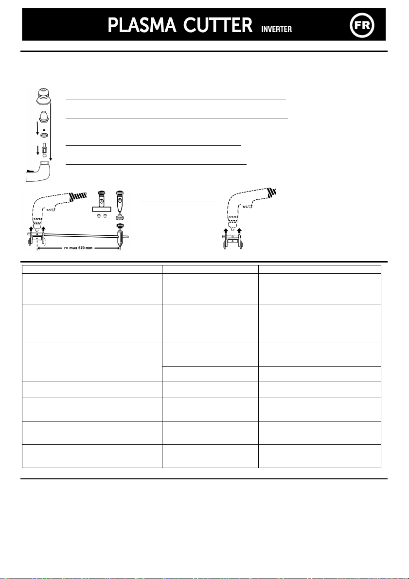
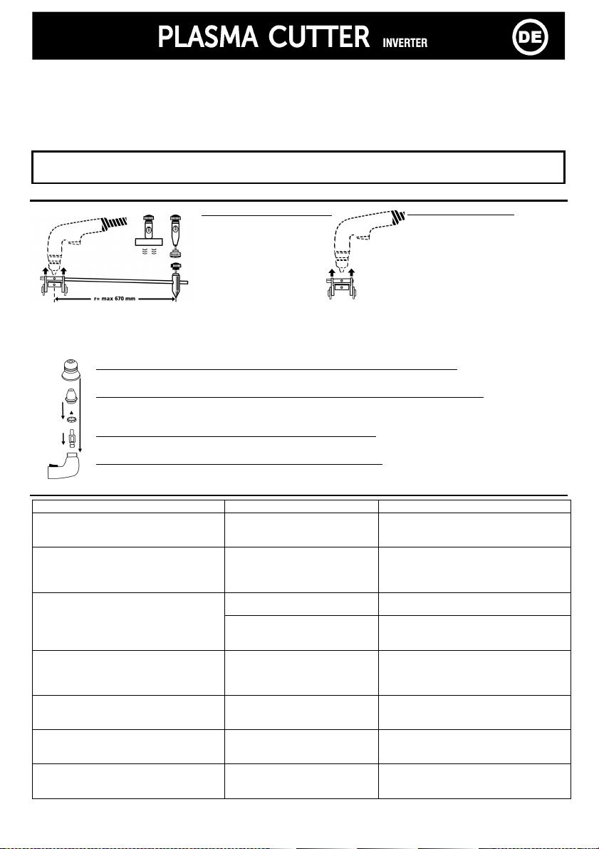
ZUBEHÖR UND VERSCHLEISSTEILE
Zubehör
Verschleißteile
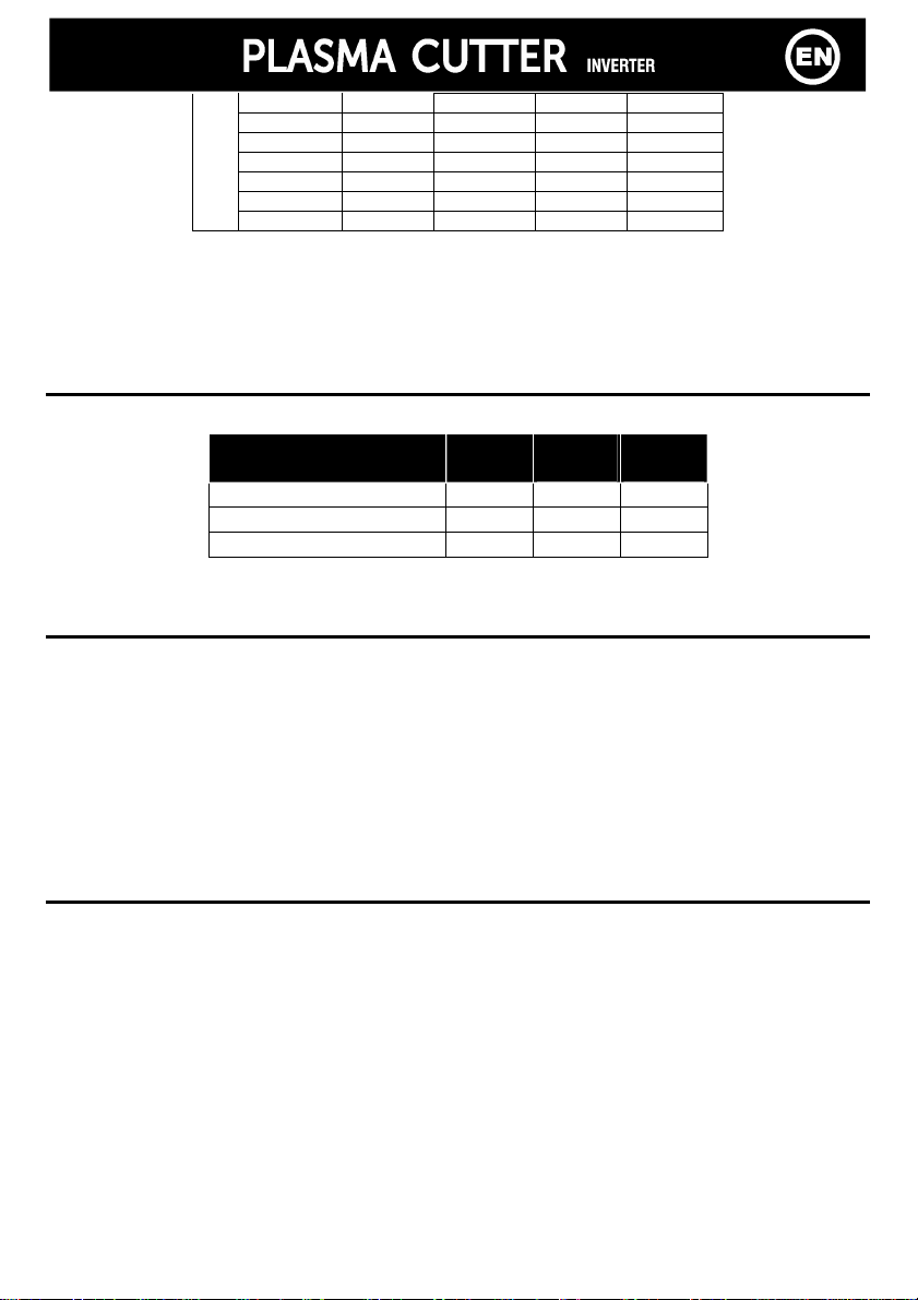
Überprüfen Sie regelmäßig den Verschleißgrad des Schutzrohres, der Düse und Elektrode und verringern Sie bei zu
hohem Verschliss die Schneidegeschwindigkeit.
st es dennoch nötig die Verschleißteile auszutauschen, wird empfohlen Düse und Elektrode gleichzeitig auszubauen.
Düse (Art-Nr. 040182 : Plasma Cutter 20 A / Art-Nr. 040236 : Plasma cutter 30 A)
Ersetzen Sie die Düse, wenn diese abgenutzt oder beschädigt ist.
Schneiddüse (Art-Nr. 040151 Plasma Cutter 20 A / Art-Nr. 040212 : Plasma cutter 30 A)
Säubern Sie die Schneiddüse, wenn sie verstopft oder verschmutzt ist.
Ersetzen Sie sie, wenn die Öffnung verformt ist oder sich um die Hälfte vergrößert hat.
Diffusor (Art-Nr. 040175 : Plasma Cutter 20 A oder cutter 30 A)
Ersetzen Sie den Diffusor, wenn die seitlichen Öffnungen verstopft sind.
Elektrode (Art-Nr. 040168 : Plasma Cutter 20 A oder cutter 30 A)
Ersetzen Sie die Elektrode, wenn sich in der Mitte ein Hohlraum ausgebildet hat.
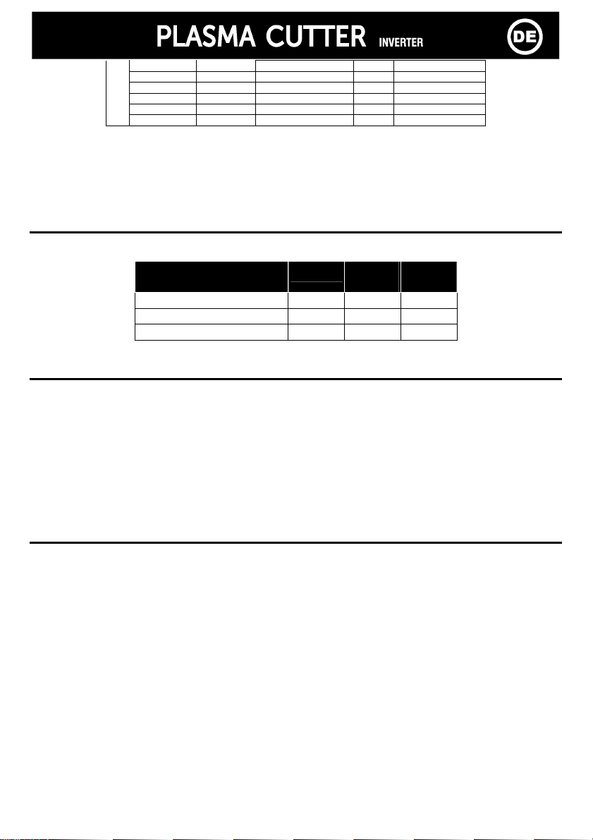
FEHLERSUCHE
Fehler Ursache Lösungen
Die grüne Netzanzeige leuchtet, das Gerät
liefert jedoch keinen Strom. Zudem leuchtet
die Fehleranzeige.
Der Überhitzungsschutz des
Gerätes wurde ausgelöst. Warten Sie bis sich das Gerät wieder
abgekühlt hat. Die Anzeige erlischt danach.
Die grüne Netzanzeige leuchtet, das Gerät
liefert jedoch keinen Strom. Zudem blinkt
die Fehleranzeige 2 Mal hintereinander
pausiert kurz um dann erneut aufzublinken.
Die Netzspannung liegt außerhalb
des zulässigen Bereiches von 230V
für plasma Cutter 20 A; 85V-265V
für plasma cutter 30 A
Überprüfen Sie zunächst die elektrische
Versorgungsspannung des Gerätes.
Schalten Sie danach das Gerät aus und
wieder ein.
Brennerdefekt Überprüfen Sie ob der Brenner richtig
angeschlossen ist. Die grüne Netzanzeige leuchtet, das Gerät
liefert jedoch keinen Strom. Zudem blinkt
die Fehleranzeige schnell. Die Luftzufuhr ist zu gering Erhöhen Sie die Luftdruckzufuhr und
schalten Sie danach das Gerät aus und
wieder ein.
Obwohl die Luftzufuhr normal funktioniert
wenn Sie den Brennertaster drücken, zündet
der Pilotlichtbogen nicht
Die Verschleißteile sind defekt
Überprüfen Sie die Verschleißteile und
wechseln Sie sie gegebenenfalls aus.
Schalten Sie danach das Gerät aus und
wieder ein.
Der Lichtbogen bricht nach ungefähr 3 sec
ab. Problem mit der Masseklemme Überprüfen Sie, ob die Masseklemme an
einem sauberen Werkstück (fett- und
farbfrei) angeschlossen wurde.
Wenn Sie bei eingeschaltetem Gerät die
Hand auf das Gehäuse legen, verspüren Sie
ein leichtes Kribbeln.
Der Schutzleiteranschluss ist
defekt Überprüfen Sie das Gerät, den Netzstecker
und hr Stromnetz.
Plasma cutter 30 A: Obwohl Sie das Gerät
ausgeschaltet haben (Position "0"), dreht
sich der Ventilator weiter.
Der Brenner befindet sich in der
Abkühlphase
Normale Reaktion des Schneidegerätes.
Warten Sie so lange, bis der Kühlvorgang
abgeschlossen ist.
Kit Kompass (Art-Nr. 040205)
Kreisausschnitte bis zu einem
Durchmesser von 134 cm
möglich. Wird mit 3
Verbindungmöglichkeiten
geliefert: Magnetisch, mit
Mittelbolzen, zum
Verschrauben
Wagen (Art-Nr. 040199)
Ermöglicht eine bequemere
Handhabung des Gerätes (Sie
können auf der vom Hersteller
empfohlenen Höhe arbeiten).
Optimierung der Schnittleistung
und Verlängerung der Haltbarkeit
der Düsen

11
DESCRIPCION
Gracias por su elección ! Para sacar el mayor provecho de su máquina, lea atentamente lo siguiente:
Los Plasma Cutter 20 A y cutter 30 A son máquinas de corte plasma nverter, portatiles, monofásicas, ventiladas.
Permiten cortar en corriente continua (DC) los aceros, inox, aluminio, cobre. Funcionan con una red eléctrica monofásica
230V para el Plasma Cutter 20 A, monofásica incluida entre 85V y 265V para el Plasma cutter 30 A. Son protegidos para
funcionar con grupos electrógenos.
ALIMENTACION – PUESTA EN MARCHA
•Este aparato se vende con un enchufe 16A tipo EEC7/7. La máquina debe conectarse a la red eléctrica 230 V (50-60
Hz) con conexión tierra. La corriente efectivamente absorbida (l1eff) está indicada sobre la máquina para las
condiciones de uso máximas. Comprobar que la alimentación y su protección (fusible o disyuntor) son compatibles
con la corriente que requiere la utilización.
• Para el Plasma Cutter 20 A/cutter 30 A, la puesta en marcha se hace por rotación del potenciómetro en la corriente
deseada (el modo espera se hace con la posición "O" del potenciómetro).
•El aparato se pone en protección si la tensión de alimentación es superiora a 265V. Para indicar este defecto, el
indicador luminoso amarillo de protección térmica parpadea 2 veces y luego se apaga. El funcionamiento normal
reanuda de nuevo unos 30 segundos después de que la tensión regrese a su campo nominal.
•Este aparato es concebido para un uso en entorno industrial o profesional según la norma C SPR 11. En otro entorno,
puede ser difícil asegurar la compatibilidad electromagnética. No utilizar en un lugar donde hay polvo metálico que
conduce la electricidad.
OPERACIÓN DE CORTE
•Enchufar el aparato a la red eléctrica y a la red de aire comprimido exterior (PLASMA Cutter 30 A únicamente)
•Regular la presión hasta que aparezcan en el manómetro 2,5 hasta 4 bares para el plasma cutter 20 A y 2,5 hasta 6
bares para el plasma cutter 30 A.
Plasma Cutter 20 A: más allá de 1500m de altura la presión atmosférica es insuficiente para permitir el
funcionamiento del compresor integrado.
Para el plasma cutter 30 A : a partir de 10 A* y con el fin de optimizar el rendimiento de corte, utilizar el
« testador de caudal de aire » con la máquina. Para esto:
-Apretar el gatillo de la antorcha (el arco se crea)
-Relajarlo, el arco se corta pero el aire sigue escurriendo durante 15 segundos aproximadamente.
-Durante este periodo, colocar el « testador de caudal de aire » con la extremidad de la antorcha y
luego ajustar el caudal de aire hasta que la bolita se situe en la zona mini/maxi.
*nb: Para un corte a -10A, posicionarse directamente a 3 bares.
•Poner en marcha el aparato.
•Regular la corriente en función del tipo y del espesor del metal a cortar.
Plasma Cutter 20 A Plasma cutter 30 A
Espesor
(mm) Corriente
(A)
Velocidad
(m/mn)
Corriente
(A)
Velocidad
(m/mn)
0,6 5 4,1
1 12 2,5
1,5 15 1,2
2,5 18 0,65
3 20 0,35
4 20 0,26 20 0,26
6 20 0,15 25 0,20
8 - - 30A 0,16
Acero
10 - - 30 0,09
0,6 8 2,5
1 12 1,2
1,6 15 0,65
2,5 20 0,25
4 20 0,15 25 0,21
6 - - 30 0,23
Aluminio
8 - - 30 0,09
•Colocar la pinza de masa con la pieza de metal a cortar en una zona decapada
•El aparato cortador PLASMA va provisto de un sistema de arco piloto que permite establecer el arco sin necesidad
de tocar la pieza a cortar. El corte puede crearse de dos maneras:
▪ Apretar el gatillo formación del arco piloto corte al entrar en contacto con la pieza.
▪ Contacto con la pieza apretar el gatillo operación de corte inmediata.
•Durante la operación de corte asegurarse de mantener el contacto entre la boquilla y la pieza a cortar

12
FACTORES DE FUNCIONAMIENTO
Los aparatos descritos tienen una característica de salida de tipo "corriente constante". Sus factores de funcionamiento,
según la norma EN60974-1 están indicados en la tabla siguiente :
X / 60974-1 @ 40°C
(T cycle =10min)
Plasma
Cutter 20 A Plasma
cutter 30 A
(230V)
Plasma
cutter 30 A
(110V)
max 26% @ 20 A 32% à 30A 25% à 30A
60% (T cycle = 10 min) 12 A 22 A 19 A
100% (Tcycle = 10 min) 11 A 18 A 15 A
Nota: las pruebas de calentamiento fueron realizadas con una temperatura ambiente y el factor de funcionamiento a
40°C fue determinado por simulación.
MANTENIMIENTO
•El mantenimiento sólo debe ser hecho por una persona calificada
•Cuidado con apagar el generador y esperar la parada del ventilador. En efecto, las tensiones y intensidades son
elevadas y peligrosas.
•Es recomendado 2 a 3 veces al año quitar la tapa y desempolvar con una pistola de aire comprimido. Aprovechar la
ocasión para comprobar las conexiones eléctricas con un instrumento isolado.
•Controlar regularmente el estado del cable de alimentación. Si esta dañado, es necesario cambiarlo por el fabricante,
por su servicio post-venta o por una persona de calificación similar, para evitar cualquier peligro.
NUESTROS CONSEJOS •Dejar las persianas libres para la entrada y la salida de aire.
SEGURIDAD
La soldadura al arco puede ser pelígrosa y causar heridas graves o mortales. Protega usted y protega a los
demas.
Tome sus precauciones contra:
Radiación del arco: protegése por una pantilla, con filtras conformes EN 169 o EN 379.
Lluvia importante Utilizar el aparato preferentemente en una atmósfera limpia (graduación de contaminación≤ 3),
vapor de agua de plano y a más de un metro de la pieza a soldar
humedad. Utilización prohibida con lluvia o nieve
Choque eléctrico: Este aparato sólo debe ser utilizado con una alimentación monofásica de 3 alambres con neutro
conectado a la tierra. No tocar las piezas bajo tensión. Comprobar que la red de alimentación
corresponda al aparato.
Caídas : No desplazar el aparato por encima de personas u objetos.
Quemaduras : Llevar trajes de trabajo ignifugados (cotón, mono o jeans).
Trabajar con guantes de protección y un mandil ignifugado.
Protega a los demas instalando biombos ininflamables, o previéndoles de no mirar al arco y
quedarse sufisacientemente lejos de la zona de corte
Riesgo de fuego : Suprimir todos los productos inflamables del espacio de trabajo. Nunca trabajar cerca de gas
inflamable.
Humos : Nunca inhalar humos y gas de soldadura, utilizar en un entorno correctamente ventilado o / y
con una extracción artificial si la soldadura está realizada adentro.
Precauciones :
Cualquier obra de soldadura :
Adicionales - en lugares que presentan riesgos de choque eléctrico,
- en lugares cerrados
- en presencia de materiales inflamables o que presentan riesgos de explosión, siempre
deben ser sumisos a una previa aprobación de un "responsable experto" y realizada en
presencia de personas formadas para intervenir en caso de urgencia.
Los medios técnicos de protección descritos en la "ESPEC F CAC ON TECN CA CE / EC 62081"
deben ser aplicados.
Soldar en posición sobrealzada está prohibido, excepto sobre plataformas de securidad.
Las personas que llevan un estimulador cardíaco deben consultar su médico antes
de utilizar estos aparatos

13
ACCESORIOS Y CONSUMIBLES
Accesorios
Consumibles
Regularmente, comprobar el estado de desgaste del tubo de protección, de la tobera y del electrodo o en caso de
reducción significativa de la velocidad de corte.
Es fuertemente recomendado remplazar a la vez la tobera y el electrodo.
Tubo (ref. 040182 : plasma cutter 20 A / ref.040236 : plasma cutter 30 A)
Remplazar en caso de fisura o de daño
Tobera (ref.040151 plasma cutter 20 A / ref.040212 : plasma cutter 30 A)
Limpiar si su interior está obstruido o sucio
Remplazar si el hueco está deformado o si el tamaño del orificio ha aumentado de mitad.
Difusor (ref.040175 : plasma 2 cutter 20 A ou cutter 30 A)
Remplazar si los orificios laterales están obstruidos.
Electrodo (ref.040168: plasma cutter 20 A ou cutter 30 A)
Replazar si se nota una cavidad importante en su centro.
ANOMALÍAS CAUSAS REMEDIOS
Anomalías Causas Remedios
El aparato no libera potencia.
El indicador verde de funcionamiento
está encendido.
El indicador de protección térmica está
encendido continuadamente.
La protección térmica del
aparato se ha puesto en
marcha.
Esperar el fin del tiempo de
enfriamiento
El aparato no libera potencia
El indicador verde de funcionamiento
queda encendido
El indicador de protección térmica
parpadea 2 veces y se apaga.
La tensión de alimentación es
superiora a 230 + 15% para los
plasma Cutter 20 A o 85– 265V
para el Plasma 30FV
Comprobar su instalación o su
grupo, luego apagar y encender
otra vez su máquina
Defecto antorcha Comprobar que la antorcha está
bien instalada
El aparato no libera potencia
El indicador verde que encendido
El indicador de protección térmica
parpadea rápidamente. Llegada de aire demasiado débil Aumentar la presión del aire
Apretando el gatillo, el aire circula pero
no se crea el arco piloto. Consumibles gastados Comprobar y cambiar los
consumibles.
El arco eléctrico se corta al cabo de 3
segundos aproximadamente. Problema de masa
Comprobar que la pinza de masa
esté bien conectada a una parte
limpia (que no sea grasa o pintada)
de la pieza a cortar
Cuando el aparato esta encendido,
poniendo el mano sobre la carrocería,
usted siente picores.
La puesta a tierra es
defectuosa.
Verificar el añadido, el enchufe y la
tierra de su instalación.
Plasma cutter 30 A : después de apagar
el plasma (posición "O), el ventilador y el
aire comprimido siguen funcionando.
Fase de enfriamiento de la
antorcha
Comportamiento normal de la
máquina, esperar el fin de la fase
de enfriamiento (+/-15 seg)
Kit compas (ref. 040205)
Para un corte circular
hasta 134 cm de diámetro.
Entregado con 3 ejes:
nmantado, de aguja, de
atornillar
Carrito (
Ref. 040199)
Para una utilización comoda
Para quedarse a distancia
recomendada para optimizar los
resultados de corte y aumentar la
duración de vida de las toberas.

14
ОПИСАНИЕ
Мы благодарим Вас за то, что вы выбрали аппарат нашей марки. Чтобы полностью использовать его
возможности, пожалуйста ознакомьтесь с данной инструкцией.
Plasma Cutter 20 A и cutter 30 A являются аппаратами плазменной резки инверторного типа, переносные,
однофазные, вентилируемые. Они позволяют резать сталь, нержавейку, алюминий, медь при постоянном токе
(DC). Аппараты работают от монофазной электрической сети на 230В для Plasma Cutter 20 A, и монофазной сети
от 85В до 265В для Plasma cutter 30 A. Они защищены для работы от электрогенератора.
ПИТАНИЕ – ЗАПУСК В РАБОТУ
•Данный аппарат поставляется с 16А- ой вилкой, типа CEE 7/7. 230В (50 - 60 Гц) с ЗАЗЕМЛЕНИЕМ для Plasma
Cutter 20 A. Plasma cutter 30 A оснащен системой « Flexible Voltage », он питатется от розетки с
ЗАЗЕМЛЕНИЕМ на 110В и 240В (50 - 60 Гц). Количество реально потребляемой энергии ( 1eff) при
интенсивном использования, указано на аппарате. Проверьте совместимость электрического питания и его
защит (предохранитель и/или авт. выключатель) с электрическим током, необходимым для работы аппарата.
•Для Plasma cutter 30 A, запуск в работу осуществляется поворотом потенциометра на желаемую величину тока
(режим ожидания – возврат потенциометра в позицию 0).
•Защита аппарата срабатывает и останавливает аппарат, если напряжение питания превышает 265 В. При этом
желтый индикатор мигает 2 раза и затем гаснет. Аппарат переходит на нормальное функционирование через
30 сек после того как напряжение питания вернулось к номинальному значению.
•Эти аппараты относятся к Классу A. Они созданы для использования в промышленной и профессиональной
среде. В любой другой среде ему будет сложно обеспечить электромагнитную совместимость из-за
кондуктивных и индуктивных помех. Не использовать в среде содержащей металлическую пыль-проводник.
•Начиная с 1 Декабря 2010, изменения нормы EN 60974-10 будут применяться к Plasma Cutter 20 A : Внимание!
Это оборудование не соответствует CE 61000-3-12. Аппараты должны быть подключены к общественной
системе питания низкого напряжения, пользователь должен удостовериться, что аппарат может быть
подключен в сеть. При необходимости проконсультируйтесь у вашего энергосистемного оператора.
РЕЗКА
•Подключить аппарат к электрической сети и к компрессору с воздухом (только для аппарата PLASMA Cutter
30 A)
•Настроить регулятор давления (только для аппарата PLASMA Cutter 20 A) таким образом, чтобы манометр
показывал от 2,5 до 6 бар для PLASMA cutter 30 A
•Включить аппарат
Plasma Cutter 20 A : На высоте превышающей 1500 м атмосферное давление недостаточно для
работы внедренного компрессора.
Для Рlasma cutter 30 A : Начиная от 10 A* в целях улучшения качества резки, используйте «тестер
расхода воздуха» поставляемый с аппаратом. Для этого :
-Нажмите на гашетку вашей горелки (появится дуга).
-Отпустите. Электрическая дуга исчезнет, но воздух будет продолждать поступать в течение
примерно 15 секунд.
-В течение этого промeжутка установите «тестер расхода воздуха» на кончик горелки, затем
настройте подачу воздуха так чтобы указатель находиля в зоне mini/maxi.
*Примечание: для резки при менее чем 10A, настраивать на 3 бара.
•Настроить силу тока в зависимости от типа и толщины металла, предназначенного для резки
Plasma Cutter 20 A Plasma cutter 30 A
Толщина
(мм) Ток (A) Скорость
(м/мин) Ток (A) Скорость
(м/мин)
0,6 5 4,1 5 4,1
1 12 2,5 12 2,5
1,5 15 1,2 15 1,2
2,5 18 0,65 18 0,65
3 20 0,35 20 0,35
4 20 0,26 20 0,26
6 20 0,15 25 0,20
8 - - 30A 0,16
Сталь
10 - - 30 0,09
0,6 8 2,5 8 2,5
1 12 1,2 12 1,2
1,6 15 0,65 15 0,65
2,5 20 0,25 20 0,25
4 20 0,15 25 0,21
6 - - 30 0,23
Алюминий
8 - - 30 0,09

15
•Установить заземляющий зажим на зачищенной части детали, предназначенной для резки.
•Аппарат PLASMA оснащён системой управления дуги, которая обеспечивает розжиг, не касаясь детали,
которую надо разрезать. Таким образом, резка может осуществляться двумя способами :
▪ Нажатие на гашетку образование управляемой дуги резка при соприкосновении с деталью
▪ Соприкосновение с деталью нажатие на гашетку последующая резка
•Во время резки следует убедиться, что сопло касается разрезаемой детали.
ОТНОСИТЕЛЬНАЯ ПРОДОЛЖИТЕЛЬНОСТЬ ВКЛЮЧЕНИЯ ПВ %
Описанные аппараты имеют выходные характеристики типа 'постоянный ток'. Значения относительной
продолжительности включения (ПВ%), согласно норме EN60974-1, описаны в следующей таблице:
X / 60974-1 @ 40°C
(T cycle = 10 min)
Plasma
Cutter 20 A Plasma
cutter
30 A
(230V)
Plasma
cutter
30 A
(110V)
max 26% @ 20 A 32% à 30A 25% à 30A
60% (T cycle = 10 min) 12 A 22 A 19 A
100% (Tcycle = 10 min) 11 A 18 A 15 A
Примечание: нагревные испытания были реализованы при температуре окружающей среды, и ПВ% при 40 °C
был определён методом симуляции.
УХОД И ОБСЛУЖИВАНИЕ
•Обслуживание аппарата должно производиться только квалифицированным персоналом.
•Всегда сначала отключите аппарат от сети, затем дождитесь остановки вентилятора. Только тогда вы можете
работать над аппаратом. Токи и напряжения внутри аппарата значительны и представляют опасность.
•Регулярно, 2-3 раза в год, снимайте крышку аппарата и очищайте его от пыли Одновременно обеспечте
проверку контактов соединений квалифицированным специалистом с помощью изолированного инструмента.
•Необходимо проверять регулярно состояние электрического шнура. Если электрический кабель повреждён, то
он должен быть заменён изготовителем, его послепродажным отделом, или квалифицированным персоналом,
во избежание всякого риска.
НАШ СОВЕТ
•Оставьте вентиляционные щели аппарата открытыми для свободной циркуляции воздуха.
ТЕХНИКА БЕЗОПАСНОСТИ
Электродуговая резка может быть опасна для здоровья и жизни.
Защитите себя и окружающих примите меры безопасности против:
Излучений дуги: защитите себя с помощью маски, снабженной фальтрами, соответствующими нормам
EN 169 или EN 379.
Сильного дождя Используйте ваш аппарат в чистой атмосфере (уровень загрязнения ≤ 3), на
водяных паров плоской поверхности и не ближе, чем в 1 м от разрезаемой детали.
влажности : Не использовать аппарат под дождём и снегом
Электроудара: данный аппарат должен быть включен в однофазную сеть с заземлением. Не касайтесь
деталей под напряжением. Убедитесь, что используемая вами сеть подходит для
данного аппарата.
Падений: Не переносите аппарат над людьми или объектами.
Ожогов: Надевайте рабочую одежду из плотных материалов (хлопок, джинс, спецодежда).
Работайте в защитных перчатках и несгораемом фартуке.
Защитите окружающих, установив несгораемые ограждения или попросите их не
смотреть на дугу и придерживаться безопасного расстояния.
Пожара : Удалите все воспламеняемые продукты из зоны сварки. Не работайте в среде горючих
газов.
Дыма : Не вдыхайте газы и дым, производимые сваркой. Использовать аппарат в хорошо
проветриваемом помещении, с искуственной вентиляцией, при резке внутри закрытого
помещения.
Дополнительные : Любая работа, связанная с плазменной резкой:
Меры - в помещениях с повышенным риском электрошока,
Предосторожности - в закрытых помещениях
- около восламеняющихся или взрывчатых материалов,
всегда должна быть предварительно подтверждена ответственным специалистом и
реализована в присутствии обученного персонала, для срочного вмешательства в
случае необходимости

16
Технические меры безопасности, описанные в "Технических Характеристиках" CE / EC
62081 должны быть соблюдены. Резка на высоте запрещена. Исключение составляет
использование рабочих площадок безопасности.
Лица использульзующие электрокардиостимуляторы должны проконсультироваться у врача
перед работой с данными аппаратами.
АКСЕССУАРЫ И РАСХОДНЫЕ МАТЕРИАЛЫ
Аксессуары
Расходные материалы
Регулярно проверяйте состояние износа защитного сопла, насадки и электрода, особенно в случае занчительного
уменьшения скорости резки.
Советуем заменять одновременно насадку и электрод.
Сопло (арт. 040182 - Рlasma Cutter 20 A / арт.040236 - Рlasma cutter 30 A)
Заменть при наличии трещин и повреждений
Насадка (арт.040151 - Рlasma Cutter 20 A / арт.040212 - Рlasma cutter 30 A)
Очистить, если насадка внутри грязная или забита.
Заменить, если отверстие деформировано или если размер отверстия увеличился вполовину.
Распылитель (арт.040175 - Рlasma Cutter 20 A и cutter 30 A)
Заменить, если боковые отверстия забиты.
Электрод (арт.040168 - Рlasma Cutter 20 A и cutter 30 A)
Заменить, если в центре появилась значительная выемка
AНОМАЛИИ ВОЗМОЖНЫЕ ПРИЧИНЫ ВАРИАНТЫ РЕШЕНИЙ
Аномалия Возможная причина Решение
Аппарат не выдает мощности.
Зеленый индикатор функци-
онирования горит. Индикатор
термозащиты беспрестанно
горит.
Сработала термическая защита
аппарата. Подождите окончания периода охлажде-
ния.
Аппарат не выдает мощности.
Горит зеленый индикатор
функционирования. Индикатор
термозащиты мигает 2 раза, и
затем гаснет.
Напряжение сети превышает
230 В + 15% для plasma cutter
20 A ; 85-265V для Plasma
cutter 30 A.
Проверьте состояние электросети или
электрогенератора, затем выключите и
снова включите ваш аппарат.
Дефект горелки. Проверьте, правильно ли собрана и
подключена горелка, затем выключите и
снова включите ваш аппарат.
Аппарат не выдает мощности.
Горит зеленый индикатор
функционирования. Индикатор
термозащиты быстро мигает. Слишком слабая подача
воздуха. Увеличьте давление воздуха, затем
выключите и снова включите ваш аппарат
При нажатии на гашетку идет
подача воздуха, но дуга не
появляется. Износ расходных материалов. Проверьте и замените расходные
материалы.
Электрическая дуга исчезает
после приблизительно 3 секунд
Проблемы с массой Проверьте, что зажим массы подключен к
чистой (не жирной и не покрашенной)
части разрезаемой детали.
Plasma cutter 30 A : после
выключения аппарата (позиция
«O») вентилятор и сжатый
воздух продолжают работать.
Цикл охлаждения горелки
Нормальное поведение аппарата.
Подождите окончания цикла охлаждения
(+/-15 сек)
Циркуль в наборе (арт. 040205)
Для круговой резки диамет-
ром до 134 см. Поставляется
с 3-мя осями: магнитной,
игольчатой и резьбовой
Тележка (арт
. 040199)
Для удобства в использовании,
и чтобы находиться на
рекомендованном расстоянии
для улучшения качества резки,
а также для увеличения срока
службы насадок.

17
Déclaration de conformité
JBDC atteste que les découpeurs plasma sont fabriqués conformément aux exigences des directives Basse tension
2006/95/CE du 12/12/2006, et aux directives CEM 2004/108/CE du 15/12/2004.
Cette conformité est établie par le respect des normes harmonisées EN60974-1 de 2005, EN 50445 de 2008, EN
60974-10 de 2007.
Le marquage CE a été apposé en 2010.
Declaration of conformity
The equipment described on this manual is conform to the instructions of low voltage 2006/95/CE of 12/12/2006,
and the instructions of CEM 2004/108/CE of the 15/12/2004.
This conformity respects the standards EN60974-1 of 2005, EN 50445 de 2008, EN60974-10 of 2007.
CE marking was added in 2010.
Konformitätserklärung
JBDC erklärt, dass beschriebene Geräte in Übereinstimmung mit den Anforderungen der folgenden europäischen
Bestimmungen: Niederspannungsrichtlinie 2006/95/CE –12.12.2006 und EMV- Richtlinien 2004/108/CE –
15.12.2004 elektromagnetische Verträglichkeit- hergestellt wurden. Diese Geräte stimmen mit den harmonisierten
Normen EN60974-1 von 2005, EN 50445 von 2008, EN60974-10 von 2007 überein.
CE Kennzeichnung: 2010
Declaracion de conformidad
JBDC certifica que los aparatos PLASMA Cutter 20 A/cutter 30 A son fabricados en conformidad con las directivas
baja tensión 2006/95/CE del 12/12/2006, y las directivas compatibilidad electromecánica 2004/108/CE del
15/12/2004. Esta conformidad está establecida por el respeto a las normas EN60974-1 de 2005, EN 50445 de
2008, EN 60974-10 de 2007.
El marcado CE fue fijado en 2010.
Декларация о соответствии
JBDC заявляет, что сварочные аппараты PLASMA Cutter 20 A/cutter 30 A произведены в соответствии с
директивами Евросоюза 2006/95/CE о низком напряжении от 12/12/2006, а также с директивами CEМ
2004/108/CE от 15/12/2004.
Данное соответствие установлено в соответствии с согласованными нормами EN 60974-1 2005 г, EN 60974-
10 2003 г..
Маркировка ЕС нанесенна в 2010 г.
01/04/10 Nicolas BOUYGUES
SAS JBDC Président Directeur Général
134 BD des Loges
53941 Saint Berthevin
HERSTELLERGARANTIE
Die Garantieleistung des Herstellers erfolgt ausschließlich bei Fabrikations- oder Materialfehlern, die binnen 12
Monaten nach Kauf angezeigt werden (Nachweis Kaufbeleg). Nach Anerkenntnis des Garantieanspruchs durch
den Hersteller bzw. seines Beauftragten erfolgen eine für den Käufer kostenlose Reparatur und ein kostenloser
Ersatz von Ersatzteilen. Der Garantiezeitraum bleibt aufgrund erfolgter Garantieleistungen unverändert.
Ausschluss:
Die Garantieleistung erfolgt nicht bei Defekten, die durch unsachgemäßen Gebrauch, Sturz oder harte Stöße
sowie durch nicht autorisierte Reparaturen oder durch Transportschäden, die infolge des Einsendens zur
Reparatur, hervorgerufen worden sind. Keine Garantie wird für Verschleißteile (z. B. Kabel, Klemmen,
Vorsatzscheiben etc.) sowie bei Gebrauchsspuren übernommen.
Das betreffende Gerät bitte immer mit Kaufbeleg und kurzer Fehlerbeschreibung ausschließlich über den
Fachhandel einschicken. Die Reparatur erfolgt erst nach Erhalt einer schriftlichen Akzeptanz (Unterschrift) des
zuvor vorgelegten Kostenvoranschlags durch den Besteller. m Fall einer Garantieleistung trägt der Hersteller
ausschließlich die Kosten für den Rückversand an den Fachhändler.

18
SCHÉMA ÉLECTRIQUE / PIÈCES DE RECHANGE
CIRCUIT DIAGRAM / SPARE PARTS
ESQUEMA ELECTRICO / RECAMBIOS
SCHALTPLAN/ ERSATZTEILE - ЭЛЕКТРИЧЕСКАЯ СХЕМА / ЗАПЧАСТИ
N° Désignation Plasma Cutter
20 A
Plasma Cutter
30 A
1 Bouton potentionmètre / Potentiometer Button/
Potentiometer/ Potentiometro/ Потенциометр регулировки
тока
73099 73099
2 Carte électronique / Electronic card / Elektronikplatine /
Tarjeta electrónica / Электронная плата 37104 97053
3 Cordon secteur 3 x 1,5 mm² / Power cord 3 x 1,5 mm² /
Netzzuleitung 3 x 1,5 mm²/ Cordón de alimentación 3 x 1,5
mm²/Сетевой шнур 3 x 1,5 мм²
21491 21491
4 Ventillateur / Fan / Ventilator / ventilador / Вентилятор 51032 51021
5 Grille / Protective screen / Ventilator- Grill / rejilla / Решетка 51011 51010
6
Pieds / Feets / Füsse / Pies / Ножки
71140 71140
ICONES/SYMBOLS/ ZEICHENERKLÄRUNG
A
Ampères Amps Ampere Amperios
Ампер
V
Volt Volt Volt Voltios Вольт
Hz
Hertz Hertz Hertz Hertz Герц
Coupage plasma Plasma cutting Plasma
Schneiden
Corte plasma Плазменная резка
Convient au découpage dans un environnement
avec risque accru de choc électrique. La source de
courant elle-même ne doit toutefois pas être placée
dans de tels locaux. Adapted for cutting in
environment with increased risks of electrical shock.
However, the current source must not be placed in
such places.
Geeignet für Schneidarbeit im Bereich
mit erhöhten elektrischen Risiken. Trotzdem sollte die
Stromquelle nicht in solchen Bereichen betrieben
werden. Adaptado al corte en un entorno que
comprende riesgos de choque eléctrico. La fuente de
corriente ella misma no debe estar situada dentro de
tales locales. Адаптирован для резки в среде с
повышенным риском электрошока. Однако сам
источник питания не должен быть расположен в
таких местах.
IP23
Protégé contre l’accès a
ux parties dangereuses
des corps solides de diam >12,5mm et chute d’
eau
(30% horizontal)
Protected against access to
dangerous parts by any solid body which Ø >
12,5mm and against water falls (30% horizontal)
Kontaktschutz zu gefärlichen Teilen mit Ø >
12,5mm und Schutz gegen Spritzwasser
Einfallwinkel 30%.
Protegido contra el acceso a
las partidas peligrosas de cuerpos solidos de
diametro >12.5mm y las caídas de agua (30%
horizontal) Защищен против доступа твердых
тел диаметром >12,5мм к опасным частям и от
воды (30% горизонт.)
Courant de soudage continu
Welding direct
current Gleichschweissstrom
La corriente de
soldadura es continua Сварка на
постоянном
токе

19
Alimentation électrique monophasée 50 ou 60Hz
Single phase power supply 50 or 60Hz
Einphasige
Netzversorgung mit 50 oder 60Hz Alimentación
eléctrica monofásica 50 o 60 Hz Однофазное
напряжение 50 или 60Гц.
Uo
Tension assignée à vide Rated no-load voltage
Leerlaufspannung Tensión asignada de vacío
Напряжение холостого хода.
U1
Tension assignée d’alimentation rated supply
voltage Netzspannung Tensión de la red
Напряжение сети
1max
Courant d’alimentation assigné maximal (valeur
efficace) Rated maximum supply current (effective
value) Maximaler Versorgungsstrom (Effektivwert)
Corriente maxima de alimentacion de la red
Максимальный сетевой ток (эффективная
мощность)
1eff
Courant d’alimentation effectif maximal
Maximum
effective supply current Maximaler tatsächlicher
Versorgungsstrom Corriente de alimentación
efectiva maxima Максимальный эффективный
сетевой ток
EN60 974-
1
L’appareil respecte la norme EN60974-1 The
device complies with EN60974-1 standard relative to
welding units Das Gerät entspricht der Norm
EN60974-1 für Schweißgeräte El aparato está
conforme a la norma EN60974-1 referente a los
aparatos de soldadura Аппарат соответствует
европейской норме EN60974-1
Convertisseur monophasé transformateur-
redresseur
Single phase inverter, converter-rectifier
Einphasiger statischer Frequenzumformer/ Trafo/
Gleichrichter Convertidor monofásico transformador-
rectificador Однофазный инвертор, с
трансформацией и выпрямлением.
@40°C
X
/10min
…%
X : Facteur de marche à …% X : duty
factor at
…% X : Einschaltdauer …% X
: Factor de
funcionamiento de …% X : Продолжительность
включения …%
% de temps d’utilisation continu jusqu’à disjonction
thermique à 20°C ambiant. % of coninuous use time
up to thermal shutdown at 20°C orresp.
Einschaltdauer unter 20°C % de tiempo en
utización continua hasta disyunción térmica, a 20°C
ambientes. % времени непрерывного
использования до срабатывания термозащиты при
температуре окружающей среды 20°C.
I2
…%
2 : courant de soudage conventionnnel
orrespondent 2 : corresponding conventional
welding current 2 : entsprechender Schweißstrom
2 : Corrientes correspondientes 2 : Токи,
соответствующие Х*
U2
…%
U2 : Tensions conventionnelles en charges
correspondantes U2 : conventional voltages in
corresponding load U2 : entsprechende
Arbeitsspannung U2 : Tensiones convencionales en
carga U2 : соответствующие сварочные
напряжения*
Appareil conforme aux directives européennes
The device complies with European Directive
Gerät entspricht europäischen Richtlinien
El aparato está conforme a las normas europeas.
Устройство соответствует европейским нормам.
Conforme aux normes GOST (Russie) Confo
rm to
standards GOST / PCT (Russia) in Ubereinstimmung
mit der Norm GOST/PCT
Conforme a la normas GOST (PCT) (Rusia)
Продукт соответствует стандарту России (РСТ)
L’arc électrique produit des rayons dangereux
pour les yeux et la peau (protégez-vous !)
The electric arc produces dangerous rays for eyes
and skin (protect yourself !)
Der elektrische
Lichtbogen verursacht Strahlungen auf Augen und
Haut (schützen Sie sich !)
El arco produce
rayos peligrosos para los ojos y la piel
(¡ Protegase !)
Электрическая дуга
производит опасные лучи для глаз и кожи
(защитите себя!)
Attention, découper
peut déclencher un feu ou
une explosion.
Caution, cutting can produce
fire or explosion. Achtung
: Schweißen kann
Feuer oder Explosion verursachen
Cuidado,
cortar puede iniciar un fuego o una explosión.
Внимание! Резка может вызвать пожар или
взрыв.
Le dispositif de déconnexion de sécurité est
constitué par la prise secteur en coordination
avec l'installation électrique domestique.
L'utilisateur doit s'assurer de l'accessibilité de la
prise. The mains disconnection mean is the
mains plug in combination with the house
installation. Accessibility of the plug must be
guaranteed by user. Die Stromunterbrechung
erfolgt durch Trennen des Netzsteckers vom
häuslichen Stromnetz. Der Gerätanwender sollte
den freien Zugang zum Netzstecker immer
gewährleisten El dispositivo de desconección
de seguridad se constituye de la toma de la red
electrica en coordinación con la instalación
eléctrica doméstica. El usuario debe asegurarse
de la accesibilidad del enchufe. Система
отключения безопасности включается через
сетевую штепсельную розетку
соответствующую домашней электрической
установке. Пользователь должен убедиться,
что розетка доступна.
Mise en veille/mise en marche standby/On
Standby / Einschalten
standby/ puesta en
marcha Включить/Режим ожидания
Attention
! Lire le manuel d’instruction avant
utilisation Caution ! Read the user manual
Achtung : Lesen Sie die Betriebsanleitung
Cuidado, leer las instrucciones de utilización.
Внимание ! Читайте инструкцию по
использованию
Produit faisant l'objet d'une collecte sélective-
Ne pas jeter dans une poubelle domestique
Separate collection required – Do not throw in a
domestic dustbin Produkt für selektives
Einsammeln. Werfen Sie diese Geräte nicht in
die häusliche Mülltonne.
Este aparato es objeto de una recolección
selectiva. No debe ser tirado en en cubo
doméstico.
Продукт требует специальной утилизации.
Не выбрасывать с бытовыми отходами.

20
17,2 kg
12 kg
Plasma
Cutter 20 A
Plasma
cutter 30 A
Voyant vert de fonctionnement
Power indicator (green)
Netzanzeige, grün (Betriebsbereit)
ndicador luminoso verde de funcionamiento
Зеленый индикатор сети
Potentiomètre de réglage courant
Current setting
Potentiometer zur Stromeinstellung
Potentiometro de reglaje de corriente
Потенциометр регулировки тока
Voyant jaune de protection thermique
Thermal protection indicator (yellow)
Übertemperaturanzeige, gelb
ndicador luminoso amarillo de protección térmica
Желтый индикатор температурной защиты
Manomètre (plasma cutter 30 A uniquement).
Manometer (only for plasma cutter 30 A).
Manometer (nur Plasma 30 A)
Manómetro (plasma cutter 30 A solamente).
Манометр (только plasma cutter 30 A)
Régulateur de pression (plasma cutter 30 A
uniquement).
Pressure regulator (only for plasma cutter 30 A).
Luftdruckregulator (nur Plasma cutter 30 A)
Regulador de presión (plasma cutter 30 A
solamente)
Регулятор давления (только plasma cutter 30 A)
6
6
nterrupteur Marche / Arrêt. (plasma cutter 20 A
uniquement)
On / OFF button. (only for plasma cutter 20 A)
Schalter ON/OFF. (nur Plasma cutter 20 A)
nterruptor arranque / paro. (plasma cutter 20 A
solamente)
Выключатель вкл/выкл. (только plasma cutter
20 A)
Other manuals for Plasma Cutter 20 A
1
This manual suits for next models
1
Table of contents
Languages:
Other JBDC Welding System manuals
Popular Welding System manuals by other brands

Chicago Welding
Chicago Welding 94164 Set up and operating instructions

Cutlass Fasteners
Cutlass Fasteners CLASSIC+CD manual

Stanley
Stanley TOP MIG 1400 user manual

Lincoln Electric
Lincoln Electric SHIELD-ARC 500AS operating manual

Elektra Beckum
Elektra Beckum MIG/MAG 170 parts manual

WELDKAR
WELDKAR WK MIG 5040 F SYNERGIC instruction manual