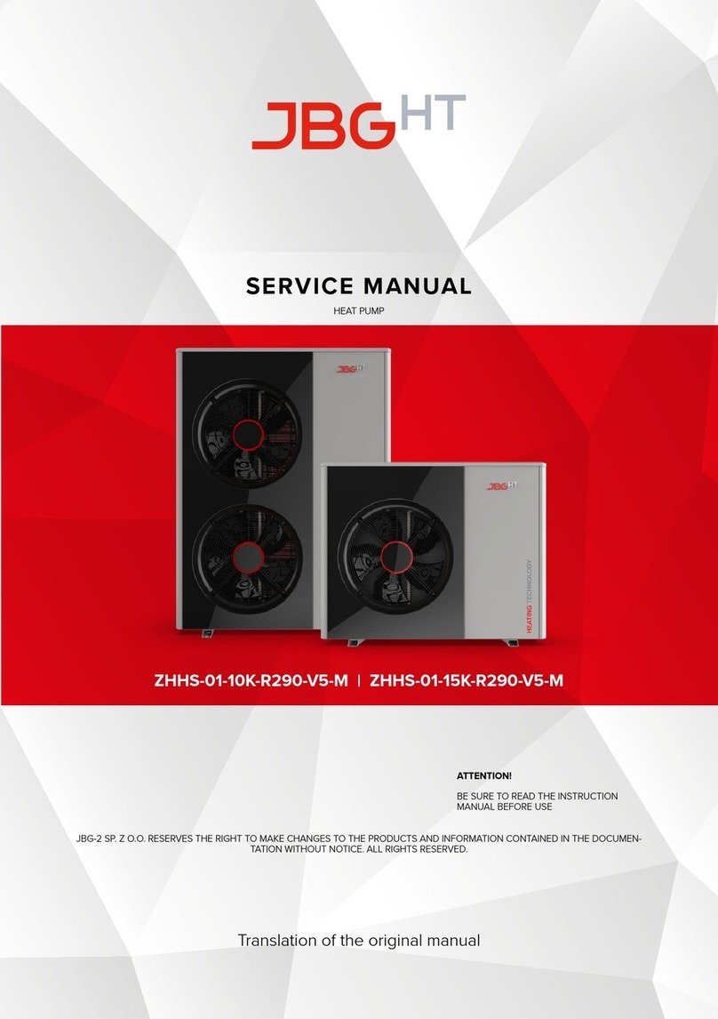
JBG HT ZHHS-01-10K-R290-V5-M User guide

ZHHS-01-10K-R290-V5-M | ZHHS-01-15K-R290-V5-M
INSTALLER MANUAL
HEAT PUMP
JBG-2 SP. Z O.O. RESERVES THE RIGHT TO MAKE CHANGES TO THE PRODUCTS AND INFORMATION CONTAINED IN THE
DOCUMENTATION WITHOUT NOTICE. ALL RIGHTS RESERVED.
Translation of the original manual
CAUTION!
IT IS ESSENTIAL TO READ THE
INSTRUCTION MANUAL BEFORE USE!


© JBG-HT (v.2.0) 3
INSTRUCTION MANUAL – HEAT PUMP
TABLE OF CONTENTS
1. CHARACTERISTICS ..................................................................5
1.1. Idea of action for the heat pump........................................................6
2. SAFETY ............................................................................6
2.1. Marking system ...................................................................... 7
2.2. Before first use .......................................................................8
2.3. Important warnings ...................................................................8
2.4. Risks as a result of product changes . . . . . . . . . . . . . . . . . . . . . . . . . . . . . . . . . . . . . . . . . . . . . . . . . . . . 9
2.5. Risks of personal injury and property damage as a result of improper maintenance and repair or
failure to do so .......................................................................9
2.6. Risk related to improper use . . . . . . . . . . . . . . . . . . . . . . . . . . . . . . . . . . . . . . . . . . . . . . . . . . . . . . . . . . .10
2.7. Risk of burn injury ....................................................................10
2.8. Risk of malfunction due to incorrect electrical supply......................................10
2.9. Risk of environmental contamination from leaking refrigerant ..............................10
3. DOCUMENTATION..................................................................10
3.1. Description of Monoblock pump operation ..............................................10
3.1.1. Product conformity (CE marking) .................................................11
3.2. Schematic of heat pump operation .....................................................11
3.2.1. Pump operation in heating mode ................................................11
3.2.2. Pump operation in cooling mode ................................................11
3.2.3. Heat pump operation envelope .................................................12
3.3. Pump design.........................................................................13
3.3.1. ZHHS-01-10K-R290-V5 Pump ....................................................13
3.3.2. ZHHS-01-15K-R290-V5 Pump ....................................................16
3.3.3. Indoor unit (Controller) Option 1 ..................................................18
3.3.4. Indoor unit Hydrobox Option 2 .................................................20
3.3.5. Indoor unit Hydrotower Option 3................................................22
3.4. Standard components................................................................24
3.5. Accessories.........................................................................24
4. SAFE TRANSPORTATION, INSTALLATION AND STORAGE................................24
4.1. General Guidelines ..................................................................24
4.2. Location of the pump in relations to noise emission......................................25
4.3. Transportation.......................................................................25
4.4. Unpacking the product ...............................................................26
4.5. Storage ............................................................................26
4.6. Mechanical installation and mounting ..................................................26
4.6.1. Setting up the outdoor unit – general guidelines..................................26
4.7. Defrost mode .......................................................................28
4.8. Electrical installation .................................................................29
4.8.1. Requirements ................................................................29
4.8.2. Diagrams of the electrical system ...............................................32
4.9. Hydraulic system ....................................................................35
4.9.1. Requirements ................................................................35
4.9.2. Hydraulic system diagrams.....................................................37
4.9.3. Diagram of the refrigeration system ..............................................41

4 © JBG-HT (v.2.0)
INSTRUCTION MANUAL – HEAT PUMP
4.9.4. Water supply system ...........................................................41
4.9.5. Filling up and venting the system ...............................................42
4.9.6. Installing the DHW sensor......................................................42
4.9.7. Initial startup .................................................................42
4.10. Installing the Internet module .........................................................43
4.10.1. WiFi connection at the User’s site (Wireless network as an output to the Internet). ....43
4.10.2. Cable connection at the User’s site (Cable network as an output to the Internet). .....43
4.10.3. Cable connection at the User’s site (to check Internet access). .....................44
4.10.4. WiFi Configuration ............................................................44
5. starting up the heat pump ...........................................................46
5.1. Controller Main Screen...............................................................46
5.2. Menu Icons ......................................................................... 47
5.3. Turning on and o ................................................................... 47
5.4. CH and DHW temperature settings .................................................... 47
5.5. Logging in . . . . . . . . . . . . . . . . . . . . . . . . . . . . . . . . . . . . . . . . . . . . . . . . . . . . . . . . . . . . . . . . . . . . . . . . . . 48
5.6. Options and settings .................................................................48
5.6.1. CH/DHW Calendar ............................................................48
5.6.2. Calendar.....................................................................48
5.6.3. Setting a schedule ............................................................49
5.6.4. Vacation Periods..............................................................49
5.6.5. Week view ...................................................................49
5.6.6. Special days .................................................................49
5.6.7. Date and time ................................................................50
5.6.8. Manufacturer .................................................................50
5.6.9. Service ......................................................................50
5.7. Quick Guide ........................................................................50
6. SETTINGS AVAILABLE TO THE SERVICE TECHNICIAN...................................57
6.1. Weather control .....................................................................57
6.2. Mixer heating curve..................................................................57
6.3. Procedure for performing evaporator defrosting.........................................58
7. MAINTENANCE, INSPECTION AND REPAIR ........................................... 58
7.1. Maintenance notes ..................................................................58
7.2. Safety parameters ...................................................................59
7.3. Disassembly and disposal ............................................................59
7.4. Error codes .........................................................................59

© JBG-HT (v.2.0) 5
INSTRUCTION MANUAL – HEAT PUMP
1. CHARACTERISTICS
MONOBLOCK HEAT PUMP
ZHHS-01-10K-R290-V5-M / ZHHS-01-15K-R290-V5-M
Performance data – heating (EN 14511)
ZHHS-01-10K-R290-V5-M ZHHS-01-15K-R290-V5-M
A7/W35
Power range (min-max) 1kW 3,38 ÷ 9,86 5,35 ÷ 14,7
Partial load 1kW 6,60 8,70
Power consumption 1kW 1,45 1,64
COP 14,56 5,29
A7/W45
Power range (min-max) 2kW 3,00 ÷ 8,89 5,22 ÷ 14,81
Partial load 2kW 5,29 8,58
Power consumption 2kW 1,44 2,15
COP 23,67 3,99
A7/W55
Power range (min-max) 3kW 2,88 ÷ 8,51 4,92 ÷ 13,76
Partial load 3kW 5,50 9,20
Power consumption 3kW 2,00 2,89
COP 32,75 3,19
A2/W35
Power range (min-max) 4kW 3,00 ÷ 9,01 4,67 ÷ 13,65
Partial load 4kW 3,00 4,67
Power consumption 4kW 0,67 0,98
COP 44,48 4,75
A-7/W35
Maximum power 5kW 6,80 11,17
Power consumption 5kW 2,47 4,08
COP 52,75 2,73
Cooling data
Pump type air / water
Refrigerant type R290
Refrigerant amount kg 0,55 0,8
Maximum working pressure bar 26
Compressor type inwerter scroll
Oil PAG PZ46M
Adjustment type electronic
Heating + DHW
Minimum working pressure bar 1,0
Maximum working pressure bar 3,0
Rated flow m³/h 1,17 1,48
External operating temperature range °C from -20 to +35
Feed water temperature °C from +20 to +65
Physical dimensions
Depth x width x height mm 535 x 1155 x 935 535 x 1155 x 1530
Weight kg 132 166
Water connections G 5/4 "
Sound power level dB 59 61
Air flow m³/h 3500 6000
Electrical data
Electrical connection V/Ph/Hz 400 / 3~ / 50
Protection rating IP24
Electric heater power (with the option of hydrobox / hydrotower) kW 3 / 6 / 9
Maximum starting current A10 13
Fan power consumption W50 100
Number of fans 1 2
Fan rotor speed RPM 700
SCOP W35 4,46 / W55 3,31 W35 4,45 / W55 3,34
Energy eciency class
Device with a regulator – feed temperature 35°C / 55°C W35 A+++ / W55 A++
Heating temperature: water I/O temperature: 30°C / 35°C, Ambient temperature: DB 7°C / WB 6°C;
Heating temperature: water I/O temperature: 40°C / 45°C, Ambient temperature: DB 7°C / WB 6°C;
Heating temperature: water I/O temperature: 50°C / 55°C, Ambient temperature: DB 7°C / WB 6°C;
Heating temperature: water I/O temperature: 30°C / 35°C, Ambient temperature: DB 2°C / WB 1°C;
Heating temperature: water I/O temperature: 30°C / 35°C, Ambient temperature: DB -7°C / WB -8°C;

6 © JBG-HT (v.2.0)
INSTRUCTION MANUAL – HEAT PUMP
1.1. Idea of action for the heat pump
The principle of the heat pump is to collect heat from the so-called low-temperature lower source (-20°C to
+35°C) and transfer the heat to the high-temperature upper source (the central heating and DHW system). This
process is carried out with electricity supplied to drive the compressor.
solar heat,
accumulated
in the ground,
heat or air
central heating system
electrical energy
~230 V or ~380 V
Qd
QB
L
Fig. 1. Principle of operation of a heat pump
In heat pump systems, it is possible to use both the hot side (upper source), e.g. for heating purposes, and the
cold side (lower source - air), e.g. for air conditioning or refrigeration. In the heat pump settings, we can select
the following modes of operation:
• Plant – central heating,
• DHW – domestic hot water,
• Plant + DHW – central heating + domestic hot water,

© JBG-HT (v.2.0) 7
INSTRUCTION MANUAL – HEAT PUMP
2. SAFETY
Before using the device, it is essential to read the instruction manual. Failure to do so may lead
to improper operation of the device, malfunction, and may endanger the lives of those operating
the device.
1 ) The manual contains rules for handling the product, both before its first start-up and during use.
2 ) The content highlights descriptions of situations to which special attention should be paid.
3 ) If the following content is not adhered to, the product may be damaged even irreparably.
4 ) The manual is an integral part of the unit, it should be delivered to the user together with the equip-
ment. The manual should be retained for reuse.
5 ) If the device is resold or possession is otherwise transferred to another party, make sure that the
manual is transferred with the device.
6 ) If any damage is detected during transport - the device must not be connected to the mains electric-
ity(contact service).
7 ) Use the device in accordance with the purpose for which it was designed.
8 ) Before connecting the device, check the correctness of the electrical connections and the eective-
ness of the grounding system.
9 ) If the warranty seals are removed, inform the service center.
10 ) Children and persons with a diagnosed disability limiting physical, sensory or mental abilities may use
the heat pump only under the supervision of a person to whom the limitations listed in this section
do not apply.
2.1. Marking system
Attention - important content. Procedure to which special attention should be paid..
Caution - a task that requires special attention. Very important information regarding use.
Electricity - information about the electrical system, tasks related
to connecting the device to the electrical network.
Gloves - activities that require additional personal protection.
A ban placed on electrical and electronic devices reminding
the public not to throw items in trash containers.
Caution - hot surfaces.

8 © JBG-HT (v.2.0)
INSTRUCTION MANUAL – HEAT PUMP
Caution - moving parts.
Warning - harmful substance, risk of suocation
Warning – risk of explosion.
Warning – sudden (loud) noise
Warning – automatic activation
Warning – low temperature
R290
Warning of fire hazard substances in combination with R290 refrigerant.
Fire, open flame and smoking prohibited.
Tab. 1. Marking system used
2.2. Before first use
The device should not be accessed by unqualified, outsiders.
Inside the device there are components powered by electric voltage, which are life-threatening
in case of direct contact. Any work in the vicinity of the electrical board must be carried out only
by qualified and authorized personnel with the appropriate professional authorizations and in compliance
with health and safety rules.
The electrical connection must be made by an electrician with the appropriate qualifications.
Installation, assembly and commissioning work should be carried out by a person with appropriate quali-
fications.
Before opening the housing, disconnect the electrical power supply.
For installation and maintenance, use appropriate tools and direct protection equipment.
External surfaces of apparatus and equipment inside the unit may be hot and cause burns.

© JBG-HT (v.2.0) 9
INSTRUCTION MANUAL – HEAT PUMP
2.3. Important warnings
The device is not intended for use by children. Read this manual before use.
Assembly, disassembly, installation work
and maintenance of the device must be
performed by qualified personnel.
It is forbidden to make any changes to the
structure of the unit. Failure to do so may result
in injury to persons or damage to the unit.
Before performing any operations on the
unit, make sure that the electrical power
to the heat pump unit is turned o.
If the power cord becomes loose or
damaged, make sure to always call
a qualified person to repair it.
The power supply to the device
must be grounded. The device should be kept away from
environments that are flammable or corrosive.
A dedicated electrical connection should be used
to power the device, otherwise, failure may occur. Do not touch the grille of the
air exhaust and outlet.
Do not direct a stream of water
directly on the device. Power leakage
or product failure may occur.
When the device is in operation, never cover it
with clothes, cloth or other material that blocks
the ventilation of the product, as this may lead to
low eciency or even malfunction of the device.
If the power cord is damaged, take the device out
of service and call a qualified person to repair it.
It is mandatory to use the appropriate heat
pump circuit breaker and make sure that the
power supply complies with the specifications.
Otherwise, the unit may be damaged.
Tab. 2. Important warnings

10 © JBG-HT (v.2.0)
INSTRUCTION MANUAL – HEAT PUMP
2.4. Risks as a result of product changes
• Never remove, bridge or block safety devices.
• Do not tamper with safety devices.
• Do not make any changes to the product, to the supply lines, to the heating circuit safety valve.
2.5. Risks of personal injury and property damage as a result of improper maintenance
and repair or failure to do so
• Perform maintenance annually before the heating season.
• Never perform repairs or maintenance work yourself.
• Have an authorized installer perform repairs and maintenance work.
• Adhere to designated maintenance intervals.
2.6. Risk related to improper use
Improper use can lead to damage to the heat pump, danger to those operating the unit and
others in the vicinity.
2.7. Risk of burn injury
The pipes from the water exchanger located in the heat pump should be carefully insulated,
since the maximum possible temperature of the pipes is 75 degrees Celsius.
2.8. Risk of malfunction due to incorrect electrical supply
Avoid interference with the operation of the product, the electrical supply should be within the speci-
fied limits:
• 3-phase: ~400 V (+10%), 50 Hz
2.9. Risk of environmental contamination from leaking refrigerant
The product contains refrigerant R290 called natural refrigerant gas. The GWP rating of this refrigerant
is 3.
Only an installer with the
proper licenses issued by the
manufacturer and protective
equipment may perform instal-
lation and maintenance work.
Installation of the unit must
be a minimum of 1m away
from windows, doors, lighting
ducts, roof windows, hatches,
drain pipes and ventila-
tion ducts due to possible
leakage of flammable gas.
R290
In case of repairs, do not use
sparking devices or other
devices that can cause an
ignition of the refrigerant.
R290
Condensate drainage must
not be introduced into the
sewer system, as it may create
an explosive atmosphere.
R290
Do not use open flames or
other devices that can heat up
the temperature to 370°C in
the heat pump environment.
In the event of a leak or suspected leak of
refrigerant, immediately turn o the unit.
Then remove any equipment from the envi-
ronment that may be a potential source of
fire and contact the service department.

© JBG-HT (v.2.0) 11
INSTRUCTION MANUAL – HEAT PUMP
3. DOCUMENTATION
3.1. Description of Monoblock pump operation
A monobloc heat pump is a compact unit containing all the components of the refrigeration system and the heat
exchanger in which the heating medium for central heating and domestic water is heated.
The outdoor unit contains refrigeration components including the fan, evaporator and compressor, condenser,
valves and auxiliary fittings. The compressor (5) pumps hot gas which goes to the four-way valve which performs
the function of switching heating/cooling modes (defrost), then the gas goes to the condenser (6) in which it gives
up heat to the medium (water, glycol) which then goes to the facility for heating or hot water. The condensed,
subcooled medium in the form of liquid goes to the electronic expansion valve (EEV)(4), where expansion takes
place, then goes to the lower heat source (evaporator)(1) the medium takes heat from the environment this is
done by air flow through a fan forced exchanger (2).
The refrigerant in the evaporator evaporates and returns in the gas fraction to the compressor.
The indoor installation is equipped with a three-way valve (3-WAY), which distributes the heated medium for
central heating or hot water purposes (in priority). In the case of very low ambient temperatures and the required
higher temperature for heating purposes, an electric heater is additionally used to raise the temperature parame-
ter of the medium, which also has a protective function in the event of failure of the refrigeration system to ensure
a positive temperature and minimize the risk of freezing of the medium in the condenser.
3.1.1. Product conformity (CE marking)
CE marking or CE marking placed on a product is a manufacturer’s declaration that the marked product conforms
to the directives so-called New Approach of the European Union.
The declaration of conformity is available for inspection from the manufacturer.
3.2. Schematic of heat pump operation
3.2.1. Pump operation in heating mode
1
3
5
6
4
2
Fig. 2. Heat pump heating mode
1Heat exchanger – evaporator, 4Electronic expansion valve,
2Fan, 5Compresser,
3Four-way valve, 6Heat exchanger – condenser.

12 © JBG-HT (v.2.0)
INSTRUCTION MANUAL – HEAT PUMP
The heat pump uses a natural refrigerant which is R290 or Propane.
Table 3 shows the dedicated gas quantity for JBG-2 pump systems
DATA ZHHS-01-10K-R290-V5 ZHHS-01-15K-R290-V5
Information on the
substance used Natural gas Natural gas
Type of factor R290 R290
GWP rating for R290 refrigerant 3 3
Amount of refrigerant in PC circuit 0.55 kg 0,8 kg
Tab. 3. Dedicated amount of refrigerant
3.2.2. Heat pump operation envelope
The heat pump is able to operate under certain conditions. Approaching the limits may cause it to go outside
the operation envelope, so in such a case safety mechanisms are activated. In the event of going outside the
operation envelope, the unit is shut down.
-25
25
-20
20
-15
15
-10 -5 0 5 10 15 20 25 30 35
45
55
65
75
35
40
ZHHS-01-10K-R290-V5-M
ZHHS-01-15K-R290-V5-M
Water temperature [ºC]
Ambient temperature [ºC]
*Applies to models:
Fig. 3. Heat pump operation envelope in heating mode

© JBG-HT (v.2.0) 13
INSTRUCTION MANUAL – HEAT PUMP
3.3. Pump design
3.3.1. ZHHS-01-10K-R290-V5 Pump
Fig. 4. Design of the heat pump outdoor unit ZHHS-01-10K-R290-V5
1Scroll compressor 11 Dehydrator filter
2Compressor inverter 12 LP Pressure transmitter
3Choke coil 13 HP Pressure transmitter
4Evaporator 14 HP Pressure switch
5Fan 15 LP Service port
6Fan support 16 HP Service port
7Fan mesh 17 Circulation pump
8Condenser 18 Flow sensor
9Electronic expansion valve EEV 19 Vent
10 Four-way valve
Tab. 4. Description of the marked parts of the heat pump outdoor unit

14 © JBG-HT (v.2.0)
INSTRUCTION MANUAL – HEAT PUMP
Front view Rear view
Photo 1. Picture of the heat pump front view Photo 2. Picture of the heat pump rear view
3.3.1.1. External dimensions
Front view Side view
Fig. 5. External dimensions of the heat pump front view Fig. 6. External dimensions of the heat pump side view
Rear view Bottom view
Fig. 7. External dimensions of the heat pump rear view Fig. 8. External dimensions of the heat pump bottom view

© JBG-HT (v.2.0) 15
INSTRUCTION MANUAL – HEAT PUMP
3.3.2. ZHHS-01-15K-R290-V5 Pump
Fig. 9. Design of the ZHHS-01-15K-R290-V5 heat pump outdoor unit
1Scroll compressor 11 Dehydrator filter
2Compressor inverter 12 LP Pressure transmitter
3Choke coil 13 HP Pressure transmitter
4Evaporator 14 HP Pressure switch
5Fan 15 LP Service port
6Fan support 16 HP Service port
7Fan mesh 17 Circulation pump
8Condenser 18 Flow sensor
9Electronic expansion valve EEV 19 Vent
10 Four-way valve
Tab. 5. Description of the marked parts of the heat pump outdoor unit

16 © JBG-HT (v.2.0)
INSTRUCTION MANUAL – HEAT PUMP
Front view Rear view
Photo 3. Picture of the heat pump front view Photo 4. Picture of the heat pump rear view
3.3.2.1. External dimensions
Front view Side view
Fig. 10. External dimensions of the heat pump front view Fig. 11. External dimensions of the heat pump side view

© JBG-HT (v.2.0) 17
INSTRUCTION MANUAL – HEAT PUMP
Rear view
Fig. 12. External dimensions of the heat pump rear view
Bottom view
Fig. 13. External dimensions of the heat pump bottom view

18 © JBG-HT (v.2.0)
INSTRUCTION MANUAL – HEAT PUMP
3.3.3. Indoor unit (Controller) Option 1
1Rear controller case
2Front controller case
3Control board
4pGDX display screen
5pGDX display screen frame
6Contactor
724V power supply
Fig. 14. Design of heat pump indoor unit Tab. 6. Description of marked parts of the heat pump indoor unit
3.3.3.1. External dimensions
Front view Side view
Fig. 15. External dimensions of the controller case front view

© JBG-HT (v.2.0) 19
INSTRUCTION MANUAL – HEAT PUMP
3.3.4. Indoor unit Hydrobox Option 2
Fig. 16. Diagram of the hydraulic module

20 © JBG-HT (v.2.0)
INSTRUCTION MANUAL – HEAT PUMP
1Casing 10 Electric heater
2Mounting panel 11 Safety thermal switch
3Mounting bracket 12 Automated vent
4Control box 13 DHW return
5pGDX screen display frame 14 CH power supply
6pGDX screen display 15 DHW power supply
7Diaphragm vessel 16 CH return
83-way valve 17 HP return
9Pressure gauge – safety bar 18 HP feed
Tab. 7. Description of the marked parts of the Hydrobox
3.3.4.1. External dimensions
Front view Side view
Top view
Fig. 17. External dimensions of the hydraulic module
Other manuals for ZHHS-01-10K-R290-V5-M
1
This manual suits for next models
1
Table of contents
Other JBG HT Heat Pump manuals
Popular Heat Pump manuals by other brands

Riello
Riello AMW P Series Installation and technical service instructions

Thermo King
Thermo King CSR40SL-143 Maintenance manual

Friedrich
Friedrich Twintemp YQ07 operating guide

STIEBEL ELTRON
STIEBEL ELTRON WPE-I 04 H 230 Premium Operation and installation

Emerson
Emerson Copeland Large ZXD120BE-TFM user manual

Ideal Boilers
Ideal Boilers 4.5 user guide