JCP PA97 User manual

INSTRUCTION MANUAL
for JCP Cartridge Tool PA97
Cartridge Calibre 6.8/11mm
The Specialist Fixing Supplier
Exclusively to the Distributor


CONTENTS
Safety Information 4
General Description 5
Warning 6
Testing Base Material 6
Using The Tool 7
Misre Procedure 7
Parts List 8/9
Fastener Selection 10
Cartridge Selection 11
Loading and Firing 12
Cleaning and Maintenance 13
Fault Finding 14

The safe use of the JCP PA97 is the responsibility of the operator. The tool must not be used
until the instruction manual has been read and understood and the operator has received
training and certication from a suitably qualied authorised instructor.
To operate this tool you must be:
1) Over 18 years of age
2) Be able to distinguish the different colour cartridges
3) Have read and understood the instruction manual
4) Be properly trained in its use
TRAINING
Training and certication must be obtained from the supplier of the tool whether it is purchased or hired.
Should proper training not be available at the point where you obtain the tool, contact JCP Construction Products
before attempting to use the tool.
Obtaining the necessary training is the responsibility of the operator.
LIMITATIONS
Just as no manual or instructions car forewarn the operator of all possible situations that may occur neither can this
instructional manual or any training that is given.
Recognising any potential risk and reacting to them in a safe way is the responsibility of the operator.
SAFETY
4

The JCP PA97 Cartridge Tool is a low velocity, indirect acting tool using the expanding gases
of a blank cartridge to drive a piston which in turn punches the fastener through the xture
into the base material. The tool works on the co-acting principle where the fastener is
always in contact with the piston to give optimum performance.
The PA97 is suitable for fasteners up to 97mm long but fasteners above 72mm need to be pre-driven into the timber
or material being xed.
DRIVE PINS AND CARTRIDGES
The PA97 is designed to take a 12mm metal washered Drive Pin suitable for use in cartridge tools, together with a
C.I.P approved 6.8/11mm Blank Strip Cartridge designed for use in these tools.
To use of any other fastener or cartridge may cause damage to the tool and could lead to serious injury or death.
SUITABLE BASE MATERIAL
Not all materials are suitable for xing into using cartridge tools. They must not be too hard, too soft or too brittle and
care must be taken to ensure the base material is suitable for the application.
Suitable Base Materials
Concrete between 20 & 50 N/mm2, Mild Steel Grade 40 to 50 and common bricks.
Unsuitable Base Materials
Tempered Steel, Cast Iron, Aluminium, Natural Hard Stone, Engineering Brick, Lightweight Blocks, Plasterboard,
Wood.
APPLICATIONS
The applications for xings made with JCP PA97 are many and varied.
They include xing timber, steel sheet, brick ties and drywall track to concrete and steel.
They can also be used for attaching plumbing and electrical ttings. These applications are only meant as a guide
and there are many others.
GENERAL DESCRIPTION
The JCP PA97 Cartridge Tool is a low velocity, indirect acting tool using the
expanding gases of a blank cartridge to drive a piston which in turn punches
the Fastener through the fixture into the base material. The tool works on the
co-acting principle where the Fastener is always in contact with the piston to
give optimum performance.
through 180° to the forward position.
The PA 97 is suitable for Fasteners up to 97mm long but Fasteners above
72mm need to be pre-driven into the timber or material being fixed.
Pull back the cocking grip as far as it will go then return it
to its original position. Return the cocking lever to the start DRIVE PINS AND CARTRIDGES
position and lock the cocking grip into place. The PA97 is designed to take a 12mm metal washered Drive Pin suitable for
use in Cartridge Tools, together with a C.I.P. approved 6.8/11mm Blank Strip
Cartridge designed for use in these tools.
Insert the cartridge strip, leading with the end with the arrow,
into the tool grip until the bottom end of the strip is flush
with the tool
SUITABLE BASE MATERIA
L
Not all materials are suitable for fixing into using Cartridge Tools. They must
not be to hard, to soft or to brittle and care must be taken to ensure the base
Place the tool perpendicular to the work surface and adopt material is suitable for the application.
a well balanced stance. Push against the tool to fully Suitable Base Material
s
depress the fastener guide then pull the trigger Concrete between 20 & 50 N/mm², Mild Steel Grade 40 to 50 and Common
Bricks
Unsuitable Base Material
s
Tempered Steel, Cast Iron, Aluminium, Natural Hard Stone, Engineering
For subsequent fixings repeat the above. The cartridge strip will advance each Brick, Lightweight Blocks, Plasterboard, Wood.
time the tool is cocked. Continue the operation until the cartridge strip is used up
then remove the strip from the top of the tool.
A
PPLICATIONS
If there are insufficient fixings required for a complete strip of 10 cartridges The applications for fixings made with JCP PA97 are many and varied.
remove the strip at the end of the fixing operation. They include fixing timber, steel sheet, brick ties and drywall track to concrete
Do not leave loaded tools unattended
.
and steel. They can also be used for attaching plumbing and electrical fittings.
These applications are only meant as a guide and there are many others.
GENERAL DESCRIPTION
3
Release the cocking grip and pivot the cocking lever
Operators must be aware of the inevitable recoil when the tool is fired.
10
Hold the tool with the muzzle pointing upwards and insert
fastener POINT FIRST into the cocking lever. The fastener
will slide down the cocking lever until it is held in place by
the magnet
LOADING & FIRING THE TOOL
The use of any other Fastener or Cartridge may cause damage to the
tool and could lead to serious injury or death.
5

Do not attempt to use Cartridge Tools without rst reading and understanding the
Instruction Manual and receiving training.
NEVER: Attempt to bypass or modify any of the safety features on the tool
Attempt to fasten into soft, thin, brittle or very hard materials
Attempt to fasten to a spalled, cracked or uneven surface
Place a hand over the muzzle end of the tool
Use the tool for other than its intended purpose
ALWAYS: Receive training before attempting to use the tool
Follow the safety precautions as they appear in this manual
Wear impact protection goggles to EN166-B or BS2092 grade 1, ear protection for levels up to
149dB, safety helmets to EN397 or BS5249, safety boots to EN345 or BS1870/4972, together
with any other safety equipment as determined by the location and application.
Ensure the base material is suitable for the application.
Follow proper edge and spacing guidelines.
TESTING BASE MATERIAL
Before fastening into any material always check it is suitable for shot ring into.
Using the fastener as a punch, strike it a rm blow with a hammer with the point in contact with the base material.
If the point is blunted the material is too hard and unsuitable, if the material shatters is too brittle and unsuitable,
if the fastener sinks into the material it is too soft and unsuitable. The fastener should leave a clear indent on the base
material without penetrating it to any depth.
WARNING
6

BEFORE USE: Make sure you have been trained in the use of the tool
Ensure tool is in safe condition
Check the tool is not loaded
Ensure the area is safe and warn other trades working nearby
Carry out a suitability test of the base material
DURING USE: Always wear suitable eye, ear and head protection as well as suitable footwear, plus any
other safety or protective equipment as may designated for the site or application.
Adopt a well balanced stance
Always point the tool away from yourself and bystanders
Never place your hand over the front of the tool
Hold the tool perpendicular to the work surface
Never x close to an edge, another xing or where a xing has failed
(See page 8 for edge and spacing distances)
Maximum repetition rate: 12 xings/minute
Noise Level: (EN15895-1)
A weighted sound level, LWA, in decibels 88
Uncertainty, KwA in decibels 3
A weighted sound level at work station, LPA in decibels 75
Uncertainty, KPA in decibels 3
Vibration Level Does not exceed 2.5m/s 2
Misre Procedure
In the event of a misre do not remove the tool from the work surface at least 20 seconds. Re-apply the tool and try
again. In event of another misre and after waiting a further 30 seconds remove the cartridge strip from the tool and
remove the fastener. Mark the tool with a DO NOT USE label and place the tool in a secure box
Contact your supplier to have the tool inspected.
After Use
Remove the cartridge strip from the tool
Inspect the tool for damage
Clean and lubricate tool
Return the tool to its box and secure in a safe place
Store the tool in a dry environment
USING THE TOOL
7

6 7
ITEM PART NO. DESCRIPTION ITEM PART NO. DESCRIPTION ITEM PART NO. DESCRIPTION ITEM PART NO. DESCRIPTION
3 SP701 Steel Liner 26 SP718 Regulating Pin 45 SP735 Stop Ring 69 SP752 Base Plate
4 SP702 Piston Guide Assembly 27 SP719 Sear 46 SP736 Cocking Grip 72 SP753 Retaining Ring
5 SP703 Piston 28 SP720 Special Screw 47 SP737 Holder 73 SP754 Retaining Ring
6 SP704 Fastener Guide 29 SP721 Spring Guide 48 SP738 Circlip 76 SP755 Fastener Symbol
7 SP705 Base Plate Assembly 30 SP722 Support Strip 50 SP739 Swivel Pin 79 SP756 Data Plate
8 SP706 Silencer Assembly 31 SP723 Special Pin 51 SP740 Special Screw 80 SP757 Retaining Plate
9 SP707 Connector Assembly 32 SP724 Special Pin Sleeve 53 SP741 Disc 96 SP758 Compression Spring
10 SP708 Firing Pin Assembly 33 SP725 Magazine Detent 56 SP742 Threaded Pin 97 SP759 Self Tapping Screw
11 SP709 Cocking Lever Assembly 34 SP726 Retention Plate 58 SP743 Fastener Detent 98 SP760 Self Tapping Screw
12 SP710 Ram Assembly 35 SP727 Nut 59 SP744 Spring 99 SP761 O-Ring
13 SP711 Cocking Lever Parts Set 36 SP728 Transport Lever 60 SP745 Pivot Pin 100 SP762 Compression Spring
20 SP712 Housing 38 SP729 Leaf Spring 61 SP746 Detent Spring 101 SP763 Compression Spring
21 SP713 Rubber Grip 39 SP730 Cover Plate 62 SP747 Pressure Pin 104 SP764 Allen Cap Screw
22 SP714 Jacket 41 SP731 Firing Pin Spring 64 SP748 Release lever 105 SP765 Allen Cap Screw
23 SP715 Trigger 42 SP732 Tension Spring 65 SP749 Dowel Pin 108 SP766 Circlip
24 SP716 Sear Guide 43 SP733 Tension Spring 67 SP750 Friction Pin 109 SP767 Dowel Pin
25 SP717 Thumbwheel 44 SP734 Compression Spring 68 SP751 Base Plate 110 SP768 Steel Pin
Retaining Ring
Piston Ring
37
38
8

6 7
ITEM PART NO. DESCRIPTION ITEM PART NO. DESCRIPTION ITEM PART NO. DESCRIPTION ITEM PART NO. DESCRIPTION
3 SP701 Steel Liner 26 SP718 Regulating Pin 45 SP735 Stop Ring 69 SP752 Base Plate
4 SP702 Piston Guide Assembly 27 SP719 Sear 46 SP736 Cocking Grip 72 SP753 Retaining Ring
5 SP703 Piston 28 SP720 Special Screw 47 SP737 Holder 73 SP754 Retaining Ring
6 SP704 Fastener Guide 29 SP721 Spring Guide 48 SP738 Circlip 76 SP755 Fastener Symbol
7 SP705 Base Plate Assembly 30 SP722 Support Strip 50 SP739 Swivel Pin 79 SP756 Data Plate
8 SP706 Silencer Assembly 31 SP723 Special Pin 51 SP740 Special Screw 80 SP757 Retaining Plate
9 SP707 Connector Assembly 32 SP724 Special Pin Sleeve 53 SP741 Disc 96 SP758 Compression Spring
10 SP708 Firing Pin Assembly 33 SP725 Magazine Detent 56 SP742 Threaded Pin 97 SP759 Self Tapping Screw
11 SP709 Cocking Lever Assembly 34 SP726 Retention Plate 58 SP743 Fastener Detent 98 SP760 Self Tapping Screw
12 SP710 Ram Assembly 35 SP727 Nut 59 SP744 Spring 99 SP761 O-Ring
13 SP711 Cocking Lever Parts Set 36 SP728 Transport Lever 60 SP745 Pivot Pin 100 SP762 Compression Spring
20 SP712 Housing 38 SP729 Leaf Spring 61 SP746 Detent Spring 101 SP763 Compression Spring
21 SP713 Rubber Grip 39 SP730 Cover Plate 62 SP747 Pressure Pin 104 SP764 Allen Cap Screw
22 SP714 Jacket 41 SP731 Firing Pin Spring 64 SP748 Release lever 105 SP765 Allen Cap Screw
23 SP715 Trigger 42 SP732 Tension Spring 65 SP749 Dowel Pin 108 SP766 Circlip
24 SP716 Sear Guide 43 SP733 Tension Spring 67 SP750 Friction Pin 109 SP767 Dowel Pin
25 SP717 Thumbwheel 44 SP734 Compression Spring 68 SP751 Base Plate 110 SP768 Steel Pin
Retaining Ring
Piston Ring
37
38
9

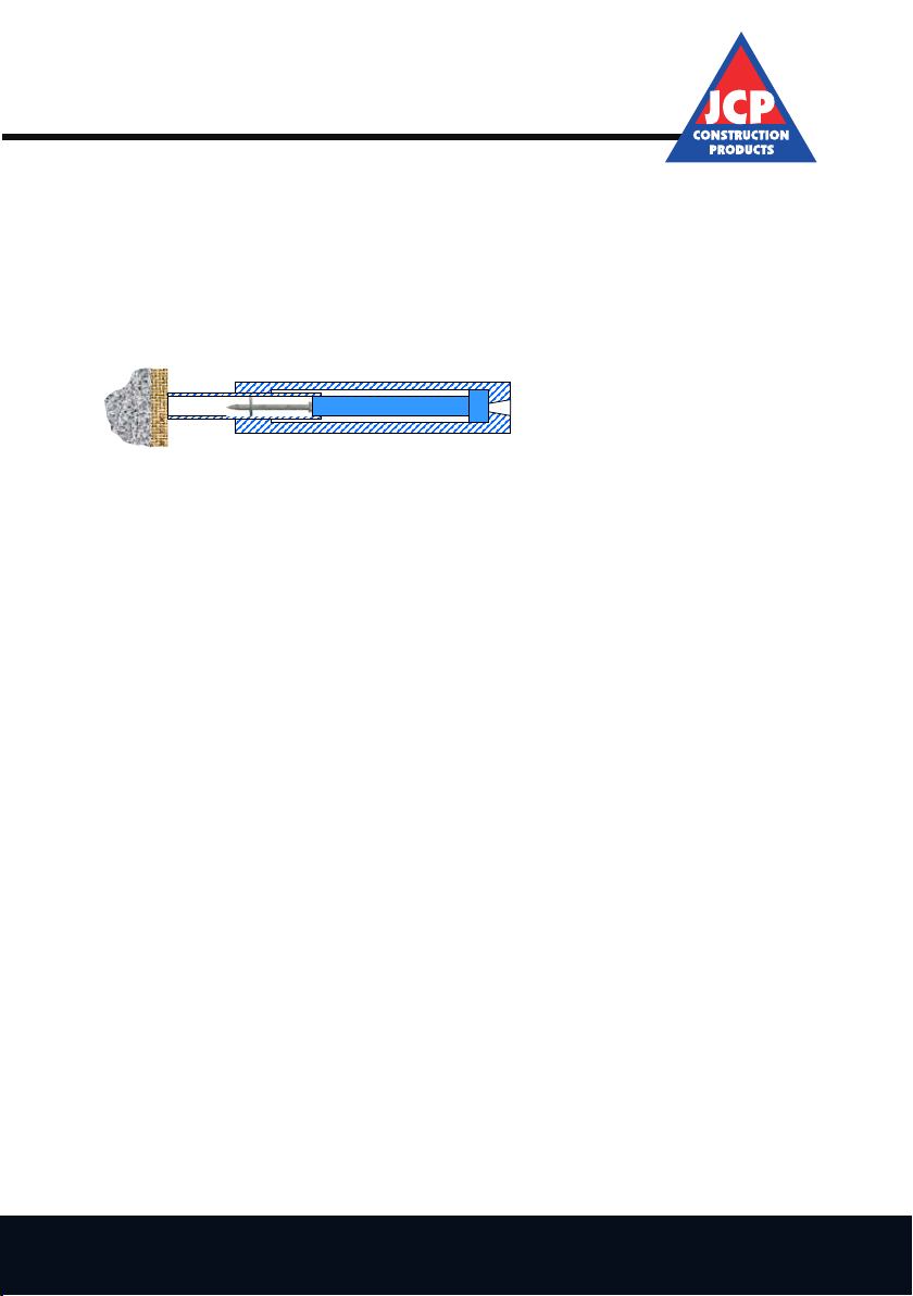
STEEL: When xing steel of a suitable type and strength the base material must be at least 4mm thick to ensure a
positive x. The length of the fastener must be the thickness of the xture (t) plus 12mm.
CONCRETE: For xing into concrete the fastener should be the thickness of the xture (t) plus 25mm.
BRICKWORK: Fixings can be made to solid brickwork but due to the variable nature of bricks extra care must be
taken. A penetration depth of between 25 & 32mm is usually required. If in doubt contact your supplier or JCP
Construction Products.
EDGE AND SPACING DISTANCES
FASTENER SELECTION
Steel Before use
Make sure you have been properly trained in the use of the tool
least 4mm thick to ensure a positive fix. The length of the fastener must be the Ensure the tool is in safe condition
thickness of the fixture (t) plus 12mm. Check the tool is not loaded
Ensure the area is safe and warn other trades working nearby
Carry out a suitability test of the base material
During use
Always wear suitable eye, ear and head protection as well as suitable
footwear, plus any other safety or protective equipment as may
designated for the site or application
Concrete Adopt a well balanced stance
For fixing into concrete the fastener should be the thickness of the fixture (t) Always point the tool away from yourself and bystanders.
plus 25mm Never place your hand over the front of the tool
Hold the tool perpendicular to the work surface
Never fix close to an edge, another fixing or where a fixing has failed.
(See page 8 for edge and spacing distances)
Maximum repetition rate 12 fixings/minute
Noise level (EN15895-1)
A-weighted sound level, LWA, in decibels 88
Uncertainty, KWA, in decibels 3
A-weighted sound level at work station, LpA, in decibels 75
Uncertainty, KpA, in decibels 3
Brickwork Vibration level Does not exceed 2.5m/s2
Fixings can be made to solid brickwork but due to the variable nature of bricks
extra care must be taken. A penetration depth of between 25 & 32 mm is usually Misfire Procedure
required. If in doubt contact your supplier or JCP Construction Products In the event of a misfire do not remove the tool from the work surface
at least 30 seconds. Re-apply the tool and try again. In event of
another misfire and after waiting a further 30 seconds remove
the cartridge strip from the tool and remove the fastener.
Spacing Edge Thickness Mark the tool with a DO NOT USE label and place the tool in a secure
Distance box
Steel 20 25 4-7mm Contact your supplier to have the tool inspected.
15 20 >7mm
Concrete 100 75 80
A
fter Us
e
A fixing to brickwork should be at least 3 courses down from the top of a wall and Remove the cartridge strip from the tool
1 full brick in from an edge. Only 1 fixing per brick should be made and do not Inspect the tool for damage
fix into mortar joints Clean and lubricate tool
Return the tool to its box and secure in a safe place.
Store the tool in a dry environment
EDGE & SPACING DISTANCES
8
When fixing to steel of a suitable type and strength the base material must be at
FASTENER SELECTION
5
USING THE TOOL
min 4 mm
12 mm
t
25
t
Spacing Edge Thickness
Distance
Steel 20 25 4-7mm
15 20 >7mm
Concrete 100 75 80
A xing to brickwork should be at least 3 courses down from the top of a wall and 1 full brick in from an edge.
Only 1 xing per brick should be made and do not x into mortar joints.
10

EDGE AND SPACING DISTANCES
The PA97 Cartridge Tool is designed to be used with 6.8/11mm calibre blank cartridges of 3 different strength,
which have been C.I.P approved.
Colour Strength Power Level Part No
Yellow Medium 4 V4LVS7Y
Red High 6 V6REDLVS27
Black Extra High 7 V7LKLVS27
Although most xings will be carried out using the red cartridge, it is recommended to start with the lowest cartridge
strength and lowest power setting, gradually increasing the power and cartridge strength until the correct fastener
penetration is achieved.
Do not overpower the tool as this may cause the fastener to break and ricochet or pass completely
through the material. It will also cause excessive wear and possible damage to the tool.
All trial xings should be made with the Power Level set to minimum and gradually increase the power until the
correct level is achieved.
ADJUSTING THE POWER LEVEL
Minimum Power
Rotate wheel to increase and decrease power
Always adjust power level before cocking tool
Maximum Power
CARTRIDGE SELECTION
The PA97 Cartridge Tool is designed to be used with 6.8/11mm calibre blank
cartridges of 3 different strength, which have been C.I.P. approved.
understanding the Instruction Manual and receiving proper training
Colou
r
Strength Power Part No
Never Level
Attempt to bypass or modify any of the safety features on Yellow Medium 4 V4LVS27Y
the tool Red High 6 V6REDLVS27
Black Extra High 7 V7BLKLVS27
Attempt to fasten into soft, thin, brittle or very hard materials
Although most fixings will be carried out using the red cartridges it is
Attempt to fasten to a spalled, cracked or uneven surface recommended to start with the lowest cartridge strength and lowest power setting
gradually increasing the power and cartridge strength until the correct fastener
Place a hand over the muzzle end of the tool penetration is achieved.
Do not overpower the tool as this may cause the fastener to break an
d
Use the tool for other than its intended purpose. ricochet or pass completely through the material. It will also caus
e
A
lways excessive wear and possible damage to the tool
.
Receive proper training before attempting to use the tool
Follow the safety precautions as they appear in this manual
Wear impact protection goggles to EN166-B or BS2092 grade 1, All trial fixings should be made with the Power Level set to minimum and gradually
ear protection for levels up to 149dB, safety helmets to EN397 increase the power until the correct level is achieved.
or BS5249, safety boots to EN345 or BS1870/4972, together
with any other safety equipment as determined by the location
and application. Minimum Power
Ensure the base material is suitable for the application
Follow proper edge and spacing guidelines. Rotate wheel to increase and decrease power.
A
lways adjust Power Level before cocking too
l
Before fastening into any material always check it is suitable for shot firing into.
Using the fastener as a punch strike it a firm blow with a hammer with the point in Maximum Power
contact with the base material. If the point is blunted the material is to hard and
unsuitable, if the material shatters it is to brittle and unsuitable, if the fastener
sinks into the material it is to soft and unsuitable. The fastener should leave a
clear indent on the base material without penetrating it to any depth.
CARTRIDGE SELECTION
9
WARNING
Do not attempt to use Cartridge Tools without first reading and
TESTING BASE MATERIAL
ADJUSTING THE POWER LEVEL
4
11

Hold the tool with the muzzle pointing upwards and insert fastener POINT FIRST into
the cocking lever. The fastener will slide down the cocking lever until it is held in place
by the magnet.
Release the cocking grip and pivot the cooking lever through 180o to the forward
position.
Pull back the cocking grip as far as it will go then return it to its original position.
Return the cocking lever to the start position and lock the cocking grip into place.
Insert the cartridge strip, leading with the end with the arrow, into the tool grip until
the bottom end of the strip is ush with the tool.
Place the tool perpendicular to the work surface and adopt a well balanced stance.
Push against the tool to fully depress the fastener guide then pull the trigger.
Operators must be aware of the inevitable recoil when the tool is red.
For subsequent xings repeat the above. The cartridge strip will advance each time the tool is cocked.
Continue the operation until the cartridge strip is used up then remove the strip from the top of the tool.
If there are insufcient xings required for a complete strip of 10 cartridges
remove the strip at the end of the xing operation.
DO NOT LEAVE LOADED TOOLS UNATTENDED.
LOADING AND FIRING THE TOOL
The JCP PA97 Cartridge Tool is a low velocity, indirect acting tool using the
expanding gases of a blank cartridge to drive a piston which in turn punches
the Fastener through the fixture into the base material. The tool works on the
co-acting principle where the Fastener is always in contact with the piston to
give optimum performance.
through 180° to the forward position.
The PA 97 is suitable for Fasteners up to 97mm long but Fasteners above
72mm need to be pre-driven into the timber or material being fixed.
Pull back the cocking grip as far as it will go then return it
to its original position. Return the cocking lever to the start DRIVE PINS AND CARTRIDGES
position and lock the cocking grip into place. The PA97 is designed to take a 12mm metal washered Drive Pin suitable for
use in Cartridge Tools, together with a C.I.P. approved 6.8/11mm Blank Strip
Cartridge designed for use in these tools.
Insert the cartridge strip, leading with the end with the arrow,
into the tool grip until the bottom end of the strip is flush
with the tool
SUITABLE BASE MATERIA
L
Not all materials are suitable for fixing into using Cartridge Tools. They must
not be to hard, to soft or to brittle and care must be taken to ensure the base
Place the tool perpendicular to the work surface and adopt material is suitable for the application.
a well balanced stance. Push against the tool to fully Suitable Base Material
s
depress the fastener guide then pull the trigger Concrete between 20 & 50 N/mm², Mild Steel Grade 40 to 50 and Common
Bricks
Unsuitable Base Material
s
Tempered Steel, Cast Iron, Aluminium, Natural Hard Stone, Engineering
For subsequent fixings repeat the above. The cartridge strip will advance each Brick, Lightweight Blocks, Plasterboard, Wood.
time the tool is cocked. Continue the operation until the cartridge strip is used up
then remove the strip from the top of the tool.
A
PPLICATIONS
If there are insufficient fixings required for a complete strip of 10 cartridges The applications for fixings made with JCP PA97 are many and varied.
remove the strip at the end of the fixing operation. They include fixing timber, steel sheet, brick ties and drywall track to concrete
Do not leave loaded tools unattended
.
and steel. They can also be used for attaching plumbing and electrical fittings.
These applications are only meant as a guide and there are many others.
GENERAL DESCRIPTION
3
Release the cocking grip and pivot the cocking lever
Operators must be aware of the inevitable recoil when the tool is fired.
10
Hold the tool with the muzzle pointing upwards and insert
fastener POINT FIRST into the cocking lever. The fastener
will slide down the cocking lever until it is held in place by
the magnet
LOADING & FIRING THE TOOL
The use of any other Fastener or Cartridge may cause damage to the
tool and could lead to serious injury or death.
IF IN DOUBT DO NOT GUESS BUT CONTACT YOUR SUPPLIER OR JCP CONSTRUCTION PRODUCTS.
12

Before any maintenance ensure the cartridge strip has been removed.
Tool should be cleaned at least once per week or after a maximum of 2500 xings.
Release cocking grip, disconnect cocking assembly from connector
assembly and unscrew baseplate.
Remove fastener guide from baseplate
Remove piston and piston guide from main body of the tool
1. Clean the tool with the brushes provided in the kit to remove all dirt and carbon deposits.
2. Check all parts for wear and damage. Pay particular attention to the stop ring on the back of the fastener guide
and to the front of the piston. Excessive wear on either of these parts can lead to serious damage to the tool.
3. Lightly lubricate the parts with the oil provided. (Part no LS100). Do not lubricate with a carbon based oil.
4. Reassemble the tool, reversing the above procedure. Do not force any parts of apply excessive pressure.
5. Dry re the tool without a cartridge or fastener to ensure correct operation.
If in doubt do not guess but contact your supplier or JCP Construction Products.
CLEANING AND MAINTENANCE
not be used until the Instruction Manual has been read and understood and the
1 Over 18 years of age Release Cocking Grip, Disconnect Cocking
Assembly from Connector Assembly and
2 Be able to distinguish the different colour cartridges unscrew Baseplate
3 Have read and understood the Instruction Manual
4 Be properly trained in its use Remove Fastener Guide from Baseplate
Training
Proper training and certification must be obtained from the supplier of the tool Remove Piston and Piston Guide from main
whether it is purchased or hired. body of the tool
Should proper training not be available at the point where you obtain the tool,
1. Clean the tool with the brushes provided in the kit to remove all dirt
and carbon deposits
Obtaining proper training is the responsibility of the Operator
.
2. Check all parts for wear and damage. Pay particular attention to
the Stop Ring on the back of the Fastener Guide and to the front
Limitations of the Piston. Excessive wear on either of these parts can lead to
serious damage to the tool.
3. Lightly lubricate the parts with the oil provided. (Part No LS100)
situations that may occur neither can this Instructional Manual or any training that Do not lubricate with a Carbon based oil
is given. 4. Reassemble the tool, reversing the above procedure
Recognising any potential risk and reacting to them in a safe way is the Do not force any parts or apply excesive pressure
responsibility of the Operator. 5. Dry fire the tool without a cartridge or fastener to ensure correct
operation.
If in any doubt do not guess but contact your supplier or JC
P
Construction Product
s
2 11
TOOL SHOULD BE CLEANED AT LEAST ONCE PER WEEK OR AFTER
A MAXIMUM OF 2500 FIXINGS
To operate this tool you must be :-
contact JCP Construction Products before attempting to use the tool.
Just as no manual or instructions can forewarn the Operator of all possible
SAFETY
The safe use of the JCP PA97 is the responsibility of the operator. The tool must
operator received proper training and certification from a suitably qualified
Authorised Instructor.
CLEANING & MAINTENANCE
Before any maintenance ensure the cartridge strip has been removed
IF IN DOUBT DO NOT GUESS BUT CONTACT YOUR SUPPLIER OR JCP CONSTRUCTION PRODUCTS.
13

FAULT CAUSE REMEDY
Tool will not fire Cartridge strip not loaded
All cartridges in strip used
Tool not fully depressed on work
surface
Firing pin not hitting cartridge
Load cartridge strip
Load new cartridge strip
Push down more on tool
Remove cartridge strip
Dry fire tool and listen for click of
firing pin moving. If not heard return
tool for repair.
Always follow misfire procedure (Page 7)
Lack of power Power setting too low
Cartridge too weak
Tool Dirty
Tool not properly cocked
Piston bent
Increase power setting on power
adjuster
Use stronger cartridge
Strip tool, clean and lubricate
Ensure piston is pushed fully to the
rear when cocking
Examine piston and replace
Fastener will not penetrate base
material
Power setting to low
Fastener too short
Base material too hard
See above
Check fastener length (page 10)
Carry out base material test
(page 6)
Fastener bends Fastener too long
Base material too hard
Check fastener length (page 10)
Carry out base material test
(page 6)
Head breaks off fastener Power setting to high Turn down power setting
Reduce cartridge strength
Fastener will not hold Fastener too short
Base material too soft
Check fastener length (page 10)
Carry out base material (page 6)
FAULT FINDING
14


Unit 14 Teddington Business Park
Station Road
Teddington
Middlesex
TW11 9BQ
0208 943 1800
www.jcpxings.co.uk
Table of contents