JDS Uniphase SKB Series User manual

SKB SERIES
FIBEROPTIC SWITCH MODULE
User Manual

ii
10109002 Rev. 001• August 2001
2001 JDS Uniphase. All rights reserved.

iii
Getting Help
For more information, contact JDS Uniphase or your local sales representative.
JDS Uniphase Corporation
570 West Hunt Club Road
Nepean, Ontario, Canada
K2G 5W8
Tel 613 727-1303
Fax 613 727-8284
E-mail sales@jdsuniphase.com
Website www.jdsuniphase.com
Instrumentation and Controls Customer Support and Service
Emergency technical support is available seven days a week, 24 hours a day:
Telephone: 1 613 727-1304, extension 4999
Global Toll Free:
Canada and U.S. 1-800-406-9559
All Other Countries: International Access Code +800-406-95599
E-mail: instrumentsupport@jdsuniphase.com
Refer to the JDSU Terms and Conditions of Sale for warranty coverage information.

iv

JDS Uniphase Terms and Conditions of Sale
The Terms and Conditions of Sale and Software license (collectively “Agreement”) contained herein constitute the entire agreement between
JDS Uniphase Corporation, or its subsidiary,as set forth on the document referencing this Agreement, (“JDSU”) and you (“Customer”). JDSU will
not be bound by any terms of Customer’s order. No form of acceptance except JDSU’s written acknowledgment sent to Customer, or JDSU’s
commencement of performance shall constitute valid acceptance of Customer’s order. Any such acceptance is expressly conditioned on assent
to the terms hereof and the exclusion of all other terms. Customer shall be deemed to have assented to the terms hereof, whether or not previ-
ously received, upon accepting delivery of any Product (as defined herein) shipped by JDSU. If tender of these terms is deemed an offer; accep-
tance is expressly limited to the terms hereof.
1. PRODUCTS
1.1 “Products” shall mean any products or services identified on (a) any of JDSU’s proposals, quotations or order acknowledgements, (b) current
applicable price lists, (c) any of JDSU’s invoices or (d) the document referencing this Agreement, in each case having the JDSU specification
applicable to the relevant product.
1.2 Alterations to any Product which JDSU deems necessary to comply with specifications, changed safety standards or governmental regula-
tions, to make a Product non-infringing with respect to any intellectual property or other proprietary interest, or to otherwise improve a Product
may be made at any time by JDSU without prior notice to, or consent of, Customer and such altered Product shall be deemed fully conforming.
2. ORDERS: Customer shall purchase Products by issuing a written purchase order signed by an authorized representative, indicating specific
Products, quantity, price, total purchase price, shipping instructions, requested delivery dates, bill-to and ship-to addresses, tax exempt certifica-
tions, if applicable, and any other special instructions. Any contingencies contained on such order are not binding upon JDSU. Allordersaresub-
ject to acceptance by JDSU, who will accept or reject orders according to JDSU’s then current processes.
3. PRICES: All prices are (a) firm for thirty (30) days from the date of quotation, (b) FCA JDSU factory [Incoterms, 2000] (shipping costs and risk
of loss from the FCA point of shipment are the responsibility of Customer) and (c) exclusive of Taxes (as defined herein) and all handling or other
charges including without limitation insurance, brokerage fees, transportation or special packaging (“Charges”). All sales are final. Title to Prod-
ucts (excluding services) shall pass from JDSU to Customer upon delivery to the shipping carrier at the FCA point. Any tax or other charge which
JDSU is liable to collect on behalf of any governmental authority (“Taxes”) as a result of the sale, use or delivery of Products, including without
limitation, duties, value added and withholding taxes, is the responsibility of the Customer, and if paid by JDSU shall be charged to Customer as
a separate item on the invoice, to the extent possible.
4. TERMS OF PAYMENT: Upon credit approval by JDSU, payment terms shall be net thirty (30) days from the date of the shipment, or in the
case of services, net thirty (30) days from the date of completion. JDSU reserves the right to require alternative payment terms including, without
limitation, letter of credit or payment in advance. If at any time Customer is delinquent in the payment of any invoice or is otherwise in breach of
this Agreement, JDSU may, at its discretion, stop performance of services or withhold shipment (including partial shipments) of any order and
may, at its option, require Customer to pre-pay for further performance or shipments. All payments not received when due shall be subject to an
additional charge of one and one half percent (1.5%) per month (annual rate 19.56%) of the unpaid amount or the maximum rate permitted by
law, whichever is less, until the date of payment. Customer grants JDSU a security interest in Products (excluding services) purchased under this
Agreement to secure payment for those Products purchased. If requested by JDSU, Customer agrees to execute financing statements to perfect
such security interest. There is no set-off right for the Customer.
5. PERFORMANCE AND SHIPPING: Performance and shipping dates specified or communicated by JDSU to the Customer are approximate
dates only and the failure to perform or ship on such dates shall not be considered a breach by JDSU. Delivery shall be deemed made upon
transfer of possession to the carrier at the FCA point. All claims for shortage of Products ordered or for incorrect charges must be presented to
JDSU within ten (10) days after receipt by Customer of the particular shipment of Products. Customer shall be responsible for all Charges.
Unless given written instruction, JDSU shall select the carrier. JDSU shall not be liable for damages or penalty for delay in delivery or for failure
to give notice of any delay, and the carrier shall not be deemed to be an agent of JDSU. Notwithstanding any provision of this Agreement, each
Product shall be deemed accepted by Customer upon delivery.
6. CANCELLATION: The Customer may not cancel, terminate, suspend performance of, or issue a hold on, any Customer order, in whole or in
part, without the prior written consent of JDSU, which consent, if given, shall be upon terms that will compensate JDSU for any loss or damage
therefrom, including but not limited to any work in process or services performed, the price of Products shipped to, manufactured for, or held sep-
arately for, the Customer, and loss of profits, incurred costs, and a reasonable allocation of general and administrative expenses relating to the
Products.
7. LIMITED PRODUCT WARRANTY: Notwithstanding any provision to the contrary (but subject to the operation of any law to the extent it can-
not be excluded), JDSU’s sole and exclusive obligations to the Customer for any Product (other than Software, as defined and warranted below
and services as warranted below) made by JDSU and sold hereunder are to repair returned Product or provide a replacement Product, at
JDSU’s sole option, for any Product which has been returned to JDSU under the RMA procedure (as defined below) and which in the reasonable
opinion of JDSU is determined to be defective in workmanship, material or not in compliance with the JDSU specification applicable to the Prod-
uct and has in fact failed under normal use on or before one (1) year from the date of original shipment of the Product. All Products, which are

experimental Products, prototypes or Products used in field trials, are not warranted. All third parties’Products (including software) sold by
JDSU carry only the original manufacturer’s warranty applicable to Customer. JDSU will only accept for repair, replacement or credit under war-
ranty Products made by third parties if expressly authorized to do so by the relevant third party. Any Product repaired or replaced under warranty
is only warranted for the period of time remaining in the original warranty for the Product. JDSU reserves the right, at its sole option, to issue a
credit note for any defective Product as an alternative to repair or replacement. The warranty provided herein shall extend to any Product which
has proved defective and has failed through normal use, but excludes and does not cover any Product or parts thereof which has been acciden-
tally damaged, disassembled, modified, misused, used in applications which exceed the Product specifications or ratings, neglected, improperly
installed or otherwise abused or is used in hazardous activities. Customer must claim under the warranty in writing not later than thirty (30) days
after the claimed defect is discovered. JDSU warrants that services will be performed in a good and workmanlike manner in accordance with
standards reasonably applicable to the services, and will reperform any services which JDSU determines are not in compliance with this war-
ranty which Customer brings to JDSU’s attention, in writing, on or before thirty (30) days immediately following completion of the applicable ser-
vice. The Customer must make all claims under these warranties and no claim will be accepted from any third party.
8. RETURN MATERIAL AUTHORIZATION PROCEDURES: JDSU will only accept Products returned under the JDSU Return Material Authori-
zation process (“RMA”). Customer shall obtain a RMA number from JDSU prior to returning any Product and return the Product prepaid and
insured to JDSU to the FCA point. Any Product which has been returned to JDSU but which is found to meet the applicable specification for the
Product and not defective in workmanship and material, shall be subject to JDSU’s standard examination charge in effect at the time which shall
be charged to the Customer. Where any Product is returned without an itemized statement of claimed defects, JDSU will not evaluate the Prod-
uct but will return it to the Customer at the Customer's expense.
9. SOFTWARE LICENSE AND WARRANTY: For software developed by JDSU and contained inany Product and all related documentation (col-
lectively “Software”), JDSU does not transfer ownership (which shall remain solely with JDSU) but only grants the Customer a perpetual, non-
exclusive license to use the Software restricted to use related only to the operation of the single Product. Such license is transferable only with
the transfer of ownership of the Product in which it is used. Except for making a backup copy or as permitted by law, Customer shall not (a) mod-
ify,reproduce, copy, reverse engineer,decompile or disassemble all or any portion of the Software, (b) distribute, market, disclose, rent, lease or
create derivative works, or sublicense the use of, the Software to any third party, or (c) permit or authorize anyone within Customer's reasonable
control to do any acts in (a) or (b). JDSU warrants that the Software under normal use and service as originally delivered to Customer will func-
tion substantially in accordance with the functional description set out in the Product specification and/or user manual supplied with the Software
for a period of ninety (90) days from the date of shipment. JDSU’s sole liability and Customer’s sole remedy for a breach of this Software war-
ranty shall be JDSU’s good faith efforts to rectify the non-conformity or, if after repeated efforts JDSU is unable to rectify the non-conformity,
JDSU shall accept return of the Product containing the non-conforming Software and shall refund to Customer all amounts paid in by Customer
in respect thereof. This warranty is void if failure of the Software has resulted from accident, misuse, abuse, misapplication or modification.
JDSU’s Software is provided to non-Department of Defense (DOD) agencies of the United States Government with RESTRICTED RIGHTS and
its supporting documentation is provided with LIMITED RIGHTS. Use, duplication, or disclosure by the United States Government is subject to
the restrictions as set forth in subparagraph "C" of the Commercial Computer Software - Restricted Rights clause at FAR 52.227-19. In the event
the sale is to a DOD agency, the Government’s rights in Software, supporting documentation, and technical data are governed by the restrictions
in the Technical Data Commercial Items clause at DFARS 252.227-7015 and DFARS 227.7202.
10. LIMITATION OF LIABILITY: EXCEPT FOR THE WARRANTIES STATED HEREIN FOR THE CUSTOMER, NO WARRANTY, CONDITION
OR REPRESENTATION, EXPRESS, IMPLIED, ORAL OR STATUTORY, IS PROVIDED TO THE CUSTOMER OR ANY THIRD PARTY,
INCLUDING, WITHOUT LIMITATION, ANY WARRANTY, CONDITION OR REPRESENTATION: (A) OF MERCHANTABILITY, FITNESS FOR
A PARTICULAR PURPOSE, SATISFACTORY QUALITY, OR ARISING FROM A COURSE OF DEALING, USAGE, OR TRADE PRACTICE;
(B) THAT THE PRODUCTS WILL BE FREE FROM INFRINGEMENT OR VIOLATION OF ANY RIGHTS, INCLUDING INTELLECTUAL PROP-
ERTY RIGHTS, OF THIRD PARTIES; OR (C) THAT THE OPERATION OF THE SOFTWARE WILL BE UNINTERRUPTED OR ERROR FREE.
THIS DISCLAIMER AND EXCLUSION SHALL APPLY EVEN IF THE EXPRESS WARRANTY HEREIN FAILS OF ITS ESSENTIAL PUR-
POSE. THE CUSTOMER'S SOLE AND EXCLUSIVE REMEDIES HEREUNDER AND THE ONLY LIABILITY OF JDSU IS EXPRESSLY LIM-
ITED TO THE TERMS OF THE AGREEMENT. JDSU SHALL NOT BE LIABLE TO THE CUSTOMER, OR ANY THIRD PARTY, FOR ANY
OTHER SPECIAL, CONSEQUENTIAL, INCIDENTAL, EXEMPLARY OR INDIRECT COSTS OR DAMAGES, INCLUDING WITHOUT LIMITA-
TION, LITIGATION COSTS, INSTALLATION AND REMOVAL COSTS, LOSS OF DATA, PRODUCTION OR PROFIT ARISING FROM ANY
CAUSE WHATSOEVER, REGARDLESS OF THE FORM OF THE ACTION, WHETHER IN CONTRACT, TORT (INCLUDING NEGLIGENCE),
STRICT LIABILITY OR OTHERWISE, EVEN IF ADVISED OF THE POSSIBILITY OF SUCH COSTS OR DAMAGES. FOR PURPOSES OF
THIS PROVISION, JDSU INCLUDES JDSU’S DIRECTORS, OFFICERS, EMPLOYEES, AGENTS, REPRESENTATIVES, SUBCONTRAC-
TORS AND SUPPLIERS. IN NO EVENT SHALL THE TOTAL COLLECTIVE CUMULATIVE LIABILITY OF JDSU, ITS EMPLOYEES, OFFIC-
ERS, AGENTS AND DIRECTORS EXCEED THE AMOUNT PAID TO JDSU FOR PRODUCTS FROM WHICH SUCH LIABILITY AROSE
DURING THE TWELVE (12) MONTH PERIOD PRECEDING THE DATE OF THE MOST RECENT CLAIM.

11. EXPORT RESTRICTIONS: Customer shall obtain all licenses, permits and approvals required by any government and shall comply with all
applicable laws, rules, policies and procedures of the applicable government and other competent authorities. Customer will indemnify and hold
JDSU harmless for any violation or alleged violation by Customer of such laws, rules, policies or procedures. Customer shall not transmit, export
or re-export, directly or indirectly, separately or as part of any system, the Products or any technical data (including processes and services)
received from JDSU, without first obtaining any licence required by the applicable government, including without limitation, the United States
Government and/or any other applicable competent authority. Customer also certifies that none of the products or technical data supplied by
JDSU under this Agreement will be sold or otherwise transferred to, or made available for use by or for, any entity that is engaged in the design,
development, production or use of nuclear, biological or chemical weapons or missile technology.
12. RIGHTS IN INTELLECTUAL PROPERTY AND TOOLING: All right, title and interest in and to any inventions, discoveries, improvements,
methods, ideas, computer and other apparatus programs and related documentation, other works of authorship fixed in any tangible medium of
expression, mask works, or other forms of intellectual property, whether or not subject to statutory protection, which are made, created, devel-
oped, written, conceived or first reduced to practice by JDSU solely, jointly or on its behalf, in the course of, arising out of, or as a result of work
performed under an order, and any related tooling, set-up, fitting-up and preparation charges whether or not invoiced, shall belong to and be the
sole and exclusive property of JDSU. Customer agrees not to reverse engineer all or any portion of any Product nor allow or assist others to do
so. Customer agrees not to remove, alter, erase, deface or cover over any markings on the Product or its packaging.
13 GENERAL TERMS:
13.1 The validity, interpretation and performance of this Agreement shall be governed by and construed under the applicable laws of the State of
New York and the United States of America, as if performed wholly within the state and without giving effect to the principles of conflict of laws.
The parties specifically disclaim the application of the United Nations Convention on Contracts for the International Sale of Goods. JDSU and
Customer hereby irrevocably and unconditionally submit to the courts of the State of New York and all courts competent to hear appeal there-
from.
13.2 JDSU shall not be liable for any delay or failure in performance whatsoever due to acts of God, earthquakes, shortage of supplies, transpor-
tation difficulties, labor disputes, riots, war, fire, explosion, epidemics, or other occurrences beyond JDSU's reasonable control or due to unfore-
seen circumstances.
13.3 Waiver by JDSU of any provision herein must be in writing and shall not be deemed to be a waiver of such provision in the future or of any
other provision.
13.4 Customer shall hold confidential and shall not use, disclose or permit others to use any confidential information identified as such in writing
or orally by JDSU or information which Customer knows or ought to reasonably know is confidential, proprietary or trade secret information of
JDSU, including, without limitation, trade secrets embodied in Products.
13.5 Neither this Agreement nor any rights under this Agreement, other than monies due or to become due, shall be assigned or otherwise trans-
ferred by Customer (by operation of law or otherwise) without the prior written consent of JDSU. This Agreement shall bind and inure to the ben-
efit of the successors and permitted assigns of the parties.
13.6 In the event that any of the terms of this Agreement, apart from payment, become or are declared to be illegal by any court of competent
jurisdiction, such terms shall be null and void and shall be deemed deleted from this Agreement, but only to the extent that such term is illegal, it
being the intent and agreement of the parties that the Agreement shall be deemed amended by modifying such term to the extent necessary to
make it legal while preserving its intent or,if that is not possible, by substituting therefor another term that is legal and achieves the same objec-
tive. All remaining terms of this Agreement shall remain in full force and effect.
13.7 Neither party has the right or authority to, and shall not, assume or create any obligation of any nature whatsoever on behalf of the other
party or bind the other party in any respect whatsoever.
13.8 JDSU neither assumes nor authorizes any third party, person or entity to assume or accept any liability or obligation, or to make any com-
mitment for JDSU with regard to JDSU services or the Products.
13.9 This Agreement constitutes the entire agreement between the parties hereto concerning the subject matter of this Agreement, apart from
existing non-disclosure agreements, and there are no understandings, agreements, representations, conditions, warranties, or other terms,
express or implied, which are not specified herein. This Agreement may only be modified by a written document executed by authorized
representatives of JDSU and Customer.

4
Contents ............................................................................................................................................ 4
List of Figures................................................................................................................................... 8
List of Tables................................................................................................................................... 10
Safety Information, Instructions, and Symbols .............................................................................1
Safety Information...................................................................................................................1
Power Requirements...................................................................................................1
Safety Instructions................................................................................................................... 1
Before Initializing and Operating the Unit....................................................................2
Operating the Unit.......................................................................................................2
Safety Symbols .......................................................................................................................3
Introduction....................................................................................................................................... 5
General Information ................................................................................................................5
Configurations .............................................................................................................6
Key Features...............................................................................................................6
Packages.....................................................................................................................6
Components................................................................................................................7
Applications................................................................................................................. 7
Standard Accessories .................................................................................................7
Latching and Non-Latching .........................................................................................7
Specifications..........................................................................................................................7
Channel Switching Times............................................................................................9
Confirming Time Between Channels...........................................................................9
Getting Started................................................................................................................................11
Before Initializing and Operating the Unit..............................................................................11
Initial Inspection ....................................................................................................................11
Operating Environment......................................................................................................... 11
Temperature..............................................................................................................11
Humidity ....................................................................................................................12
Storing and Shipping.............................................................................................................12
Claims and Repackaging ..........................................................................................12
Returning Shipments to JDS Uniphase.....................................................................12
Cleaning Connectors.............................................................................................................13
Storing Fiberoptic Connectors...............................................................................................14
Handling Fiberoptic Cables................................................................................................... 14
Installation and Physical Interface................................................................................................15
Overview of Physical Interfaces............................................................................................15
Physical Interface..................................................................................................................15
Physical Interface: The SKB Connector....................................................................15
Physical Interface: Connecting to the SKB Connector..............................................16
Physical Mounting and Connection...........................................................................17
Operating and Maintenance Instructions ..............................................................................18
Pinout Information for the Switch ..............................................................................18
Contents

5 Contents
Operation and Control Instructions..............................................................................................23
Connecting Power................................................................................................................. 24
Architecture Overview of the RS485 Serial and Enhanced Parallel Interfaces..................... 24
Command Packet Format ......................................................................................... 24
Response Packet Format.......................................................................................... 25
Parameter Data Types.............................................................................................. 25
Byte Order................................................................................................................. 25
Operation and Control using the RS485 Serial Interface.......................................... 26
Connecting Multiple Switches using the RS485 Interface.........................................26
Addressing using the RS485 Serial Interface ........................................................... 27
Protocol for the RS485 Serial Interface.....................................................................27
Operation and Control using the Simplex Parallel Interface (SK/SP Emulation Mode) .......30
The Simplex Parallel Interface (Emulation Mode).....................................................30
Simplex Parallel Interface: Pin Functional Description.............................................30
Data Lines (D0 to D6) ............................................................................................... 30
/Reset Input Line....................................................................................................... 31
/Strobe Input Line......................................................................................................31
Busy Output Line....................................................................................................... 31
Error Output Line....................................................................................................... 31
Timing ....................................................................................................................... 32
Timing Key ................................................................................................................ 32
Operation and Control using the Enhanced Parallel Interface.............................................. 33
Enhanced Parallel Interface...................................................................................... 33
Enhanced Parallel Interface Voltage Levels .............................................................33
Enhanced Parallel Timing ......................................................................................... 33
Enhanced Parallel Interface Line Descriptions ......................................................... 34
Data Lines (D0...D7) ................................................................................................. 34
/SOP Input Line......................................................................................................... 34
/STROBE Input Line.................................................................................................. 34
R/W Input Line .......................................................................................................... 34
BUSY Output Line..................................................................................................... 34
ERROR Output Line.................................................................................................. 34
/RESET ..................................................................................................................... 34
Protocol for the Enhanced Parallel Interface.............................................................35
Read Cycle................................................................................................................ 35
Write Cycle................................................................................................................ 35
Commands ...................................................................................................................................... 39
Common Commands............................................................................................................ 39
Configuration Commands ..................................................................................................... 56
Application Notes ........................................................................................................................... 77
APPLICATION NOTE: Using the ATTENTION Output Line................................................77
APPLICATION NOTE: Using the TRIGGER Input Line.......................................................77
APPLICATION NOTE: Enhanced Parallel Communication Examples................................ 78
Write Cycle................................................................................................................ 78
Read Cycle................................................................................................................ 80
APPLICATION NOTE: RS-485 Packet Examples ............................................................... 82
RS485 Packet Example ............................................................................................ 83
APPLICATION NOTE: CRC Examples................................................................................84
CRC Generation........................................................................................................ 84

6
C-Code Generation of CRC Example .......................................................................85
APPLICATION NOTE: Implementationof the SKB in an existing SK/SP Application (usingthe
Simplex Parallel Interface)................................................................................................................87
SK/SP to SKB Pinout comparison and Harness Wiring............................................88
APPLICATION NOTE: Controlling An SKB Switch using a PC Printer Port........................90
Setting the Computer to EPP Mode..........................................................................90
Using the Printer Port................................................................................................90
APPLICATION NOTE: Custom SKB with D Subminiature Style connectors.......................91
Connector Description...............................................................................................92
The Power and Serial Interface Connector...............................................................93
The Parallel Interface................................................................................................94
Service .............................................................................................................................................97
Returning a Unit....................................................................................................................97
Shipping a Unit......................................................................................................................97

8
List of Figures
SKB Switch............................................................................................................................................5
Configuration Examples ........................................................................................................................6
1xN Configuration.................................................................................................................................6
Connector Cleaning (connector type can vary) ...................................................................................13
The IDE 2x25 Connector on an SKB Switch ......................................................................................16
SKB Switch IDE Connector Dimensions............................................................................................16
Additional Dimensions ........................................................................................................................18
Preferred RS485 Bus Architecture ......................................................................................................27
RS485 Link-Layer Packet and Command Packet................................................................................28
RS485 ACK Packet .............................................................................................................................28
RS485 Network Implementation .........................................................................................................29
Typical Controller Connections...........................................................................................................30
Timing Diagram...................................................................................................................................32
Flowchart of Read Cycle .....................................................................................................................36
Flowchart of Write Cycle ....................................................................................................................37
SKB enhanced mode 5-byte write (master to slave) – high-speed......................................................79
SKB enhanced mode 5-byte write (master to slave) – low-speed .......................................................80
Three-byte response packet read from SKB – high speed...................................................................81
Three-byte response packet read from SKB – low speed....................................................................82
SKB with SK/SP Emulation Adaptor Harness ....................................................................................87
SKB to SK/SP Adapter Cable Assembly Drawing..............................................................................89
Connector and Port Locations..............................................................................................................92
Mounting Hole Location......................................................................................................................93
Pin Assignment....................................................................................................................................93
Pin Assignment....................................................................................................................................94

10
List of Tables
Safety Symbols ..................................................................................................................................... 3
Optical Specifications1,2,3................................................................................................................... 7
Other Specifications.............................................................................................................................. 8
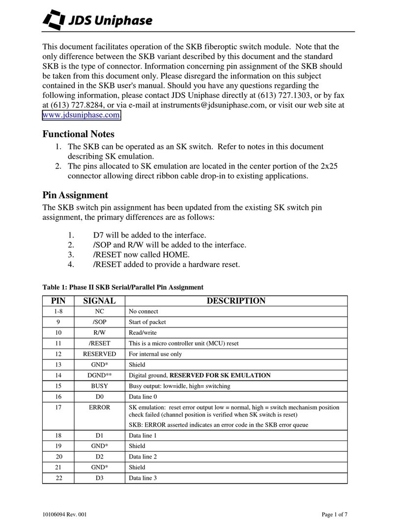
Pin Assignment: RS485 Serial Interface (on 25x2 IDE connector) .................................................. 19
Pin Assignment: Simplex (SK/SP Emulation) Parallel Interface (on 25x2 IDE connector)............. 19
Pin Assignment: Enhanced Parallel Interface (on 25x2 IDE connector)........................................... 20
Pin Assignment: Power using the 4x1 Power Connector .................................................................. 22
Pin Assignment: Power using the Power Pins on the 25x2 IDE Connector...................................... 22
Parameter Data Types......................................................................................................................... 25
RS485 Addresses................................................................................................................................ 27
RS485 Link-Layer Packet Fields........................................................................................................ 28
Channel Address Table....................................................................................................................... 31
Timing Key......................................................................................................................................... 32
Enhanced Parallel Interface States...................................................................................................... 33
SKB II to SK Adapter Harness Wiring............................................................................................... 88
Cable Wiring for Printer Port LPT2 Use ............................................................................................ 91
Pin Assignment................................................................................................................................... 94
Pin Assignment................................................................................................................................... 95

1
Safety Information, Instructions, and Symbols
Safety Information
Power Requirements
The unit can operate from a DC power source that supplies 5 V. The maximum power consumption is
1 to 2.5 A, depending on the configuration.
Safety Instructions
The following safety instructions must be observed whenever the unit is operated, serviced, or
repaired. Failure to comply with any of these instructions or with any precaution or warning contained
in the user’s manual is in direct violation of the standards of design, manufacture, and intended use
of the unit. JDS Uniphase assumes no liability for the customer’s failure to comply with any of these
safety requirements.

2 Safety Information, Instructions, and Symbols
Before Initializing and Operating the Unit
•Inspect the unit for any signs of damage, and read the user’s manual thoroughly.
•Install the unit as specified in the Getting Started section on page 11.
•Ensure that the unit and any devices or cords connected to it are properly grounded.
Operating the Unit
Warning
To avoid the risk of injury or death, always observe the following precautions before initial-
izing the unit:
•If using a voltage-reducing autotransformer to power the unit, ensure that the common
terminal connects to the earthed pole of the power source.
•Do not interrupt the protective earth grounding. Any such action can lead to a poten-
tial shock hazard that can result in serious personal injury. If an interruption to the pro-
tective grounding is suspected, ensure that the unit remains inoperative.
•Never look into the end of an optical cable connected to an optical output device that
is operating. Laser radiation is invisible, and direct exposure can severely injure the
human eye. For more information, see the user’s manual of the laser source in use.
•Turning off the power to the device does not always block the externally supplied radi-
ation to the connector at the output of the unit.
•Do not use the unit outdoors.
•To prevent potential fire or shock hazard, do not expose the unit to any source of
excessive moisture.
•Do not operate the unit when its covers or panels have been removed.
•Unless absolutely necessary, do not attempt to adjust or perform any maintenance or
repair procedure when the unit is opened and connected to a power source.
•Repairs are to be carried out only by a qualified professional.
•Do not attempt any adjustment, maintenance, or repair procedure to the unit’s internal
mechanism if immediate first aid is not accessible.
•Disconnect the power from the unit before adding or removing any components.
•Operating the unit in the presence of flammable gases or fumes is extremely hazard-
ous.
•Do not perform any operating or maintenance procedure that is not described in the
user’s manual.
•Some of the unit’s capacitors can be charged even when the unit is not connected to
the power source.

Safety Information, Instructions, and Symbols 3
Safety Symbols
The following symbols and messages can be marked on the unit (Table 1). Observe all safety
instructions that are associated with a symbol.
Table 1: Safety Symbols
Symbol Description
Laser safety. See the user’s manual for instructions on handling and operating the unit
safely.
See the user’s manual for instructions on handling and operating the unit safely.
Electrostatic discharge (ESD). See the user’s manual for instructions on handling and
operating the unit safely.
Frame or chassis terminal for electrical grounding within the unit.
Protective conductor terminal for electrical grounding to the earth.
WARNING The procedure can result in serious injury or loss of life if not carried out in proper compli-
ance with all safety instructions. Ensure that all conditions necessary for safe handling
and operation are met before proceeding.
CAUTION The procedure can result in serious damage to or destruction of the unit if not carried out
in compliance with all instructions for proper use. Ensure that all conditions necessary for
safe handling and operation are met before proceeding.

5
Introduction
General Information
This user’s manual for the SKB Series Fiberoptic Switch Module contains complete operating
instructions.
The SKB modular 1xN controllable switch controls up to four 1xN optical switches, with configura-
tions up to 100 channels. Small and rugged, the switch is designed to be used in embedded applica-
tions. It is available in single-mode (SM) and multimode (MM) versions. It has several features that
reduce installation and support efforts. The switch offers low insertion loss and is independent of
data format and direction (bidirectional).
Figure 1: SKB Switch
The standard single-pole configuration consists of a single-common port that can be aligned to any
one of 26 ports. In electrical terms, the SKB switch is a single-pole, 26-throw switch. The switching
mechanism uses collimating lenses that eliminate problems associated with modal noise, and pro-
vide low insertion loss and high repeatability.
The SKB Series Fiberoptic switch is backward compatible with the JDS Uniphase SK Series Fiberop-
tic Switch Module and SP Series Fiberoptic Switch Module.
The switch provides the capability of readable switch parameters.
The optics can be internally connected to provide custom solutions at the customer’s request.
Other manuals for SKB Series
1
Table of contents
Other JDS Uniphase Switch manuals