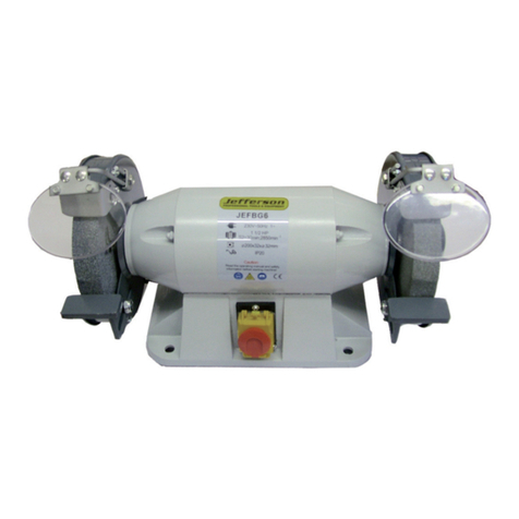
Jefferson JEFBGS06 User manual

150mm Bench Grinder
370W / ½Hp • 2850rpm • 230V /50Hz
USER MANUAL
www.jeffersontools.co.uk
JEFBGS06

JEFBGS06
150mm Bench Grinder
A. Personal Protection:
• Always suitable eye protection when using this equipment and ensure protection level is sufcient for the work
being undertaken.
• Always wear a dust mask or respirator when dusty is generated.
• Never operate this equipment wearing loose clothing or jewellery - keep long hair tied back.
• Never use the equipment when tired or under the influence of drugs, alcohol or medication.
• Keep hands clear of the driving wheels at all times.
• Never reach behind or beneath the grinding wheels when the grinder is running.
Please note: The grinding wheels will continue to rotate after the tool is switched off - it is important that you allow
the wheels to stop fully before carrying out any work on the equipment.
B. Storage and Working Environment:
• This equipment is designed for indoor use in well-lit, dry and well ventilated environments. Do not use in damp
conditions to avoid electric shock.
• Keep children and bystanders out of the work area when the tool is in operation.
• This equipment can generate sparks when in use so it is important that you ensure that the work area kept clear of
all ammable materials, liquids and gasses.
Warning: Please read all safety instructions carefully before use to avoid the risk of accident or personal injury.
2. General Safety Guidelines:
1. Technical Specifications
Model: JEFBGS06
Motor Type: Induction
Input Power: 230V / 50Hz:
Output Power: 370W (½HP)
Wheel Diameter: 6" (150mm)
Wheel Width: ¾" (20mm)
Arbor Hole: ½" (12.7mm)
No Load Speed: 2850rpm
Wheel Grits: 36 (Course)
60 (Course)
JEFBGS06
150mm Bench Grinder
Table of Contents
1. Technical Specifications page 2
2. General Safety Guidelines page 2
3. Box Contents / Machine Parts Itinerary page 3
4. Parts Identified page 3
5. Assembly Instructions page 4
6. Operating Instructions page 8
7. Maintenance page 8
8. Troubleshooting Guide page 9
9. Parts Diagram page 11
10. Parts List page 12
11. Declaration of Conformity page 13
1. 2.

JEFBGS06
150mm Bench Grinder
C. Equipment Safety:
•Check that the power switch is set to the "Off" position before connecting it to the mains power supply.
• Always ensure that all grinding wheel lock nuts, securing bolts, clamps and guards are tightened and secure before
operation.
• Always disconnect this equipment from the power supply before carrying out any adjustments or maintenance.
• This equipment is designed for indoor use in well-lit, dry and well ventilated environments. Do not use in damp
conditions to avoid electric shock.
• Keep all guards in place and in good condition.
• Replace cracked, damaged or worn grinding wheels immediately.
• When tting a new grinding wheel, always check that the RPM is equal or lesser than the RPM stated on the grinder.
Ensure that the new wheel is free from damage or aws before tting.
• During start-up, stand to one side of the grinder and switch to the "On" position. Let the grinder operate at full
speed for approximately one minute to allow any undetected aws or cracks become apparent.
• Ensure that all accessories are compatible with this model or recommended by the manufacturer.
• Never attempt to cut anything with the grinding wheel.
• Never overtighten spindle nuts.
• All service and maintenance tasks on this equipment should be carried out by authorised and qualied technicians.
• Adjust tool rests whenever necessary to maintain a distance of 1/8" (32mm) from the grinding wheel.
D. Electrical Safety:
• Ensure that all cables & plugs are in good condition before use.
• Ensure that the equipment is grounded before use. Grounding helps to ensure that the current will take the path of
least resistance in the event of an electrical malfunction or short circuit thereby reducing the risk of electric shock for
the operator.
• This machine is equipped with an electrical cord that has an equipment grounding conductor and a grounding plug.
The plug must be plugged into a compliant outlet that has been properly installed and grounded in accordance with
current specications and ordinances.
• Never modify the plug provided. If it does not t the outlet ensure that the correct outlet is installed by a qualied
technician.
E. Using Extension Cables
• Ensure that all extension cables are compatible for use with the tool and that they are correctly wired and free
from wear and damage.
• Ensure that the extension cords are heavy enough to carry the current drawn by this equipment. If the extension
cable is not heavy enough - a drop in voltage can occur - resulting in loss of power and overheating and damage to
the motor that is not covered under warranty.
JEFBGS06
150mm Bench Grinder
3. Box Contents / Machine Parts Itinerary
ITEM QTY
Left Work Rest 1
Right Work Rest 1
Plain Eye Shield 1
Eye Shield Fixing Knob 1
Eye Shield Mounting Rod (1 left, 1 right) 2
Eye Shield Assembly Mounting Bolt M6x30 2
Eye Shield Assembly Mounting Washer D6 2
Eye Shield Assembly Mounting Locking Washer D6 2
Work Rest Fixing Knob 2
Work Rest Fixing Pain Washer D5 2
Work Rest Fixing Locking Washer D5 2
Coolant Tray 1
Spark Deflector 2
Spark Deflector Fixing Screw Assembly 2
4. Parts Identified
Fig.1 - Parts
3. 4.

JEFBGS06
150mm Bench Grinder
5. Assembly Instructions
A. Mounting the Grinder to the Workbench
Before using the grinder it is essential that you rst mount it to a work bench or grinding stand/pedestal.
Caution: Bench grinders vibrate. Grinder movement
during high-speed rotation may cause injury or damage
to the workpiece or operator.
1. Position the grinder on the workbench
2. Mark the workbench through the two mounting holes located in
the grinder base.
3. Drill holes in the workbench at the marks
4. Using two long bolts, lock bolts, lock-washers and nuts (parts not
supplied) secure the grinder to the workbench as shown in Fig.2.
Fig.2 Mounting
B. Eye Shield Assembly
Eye shields must be installed before using this equipment.
1. Mount the left and right shield rods to the inside of the wheel guards using the hex mounting bolts
(M6x30) provided.
2. Once the shield rods are rmly in place, slide the shield bracket onto the shield rod.
3. Tighten the carriage bolt, leaving it loose enough to allow the safety shield to be raised and lowered easily.
Note: The eye shield should move freely when adjusted but stay fixed when the locking knob is tightened.
Fig.3 Eye Shield pt1 Fig.4 Eye Shield pt2
JEFBGS06
150mm Bench Grinder
5. Assembly Instructions (continued)
C. Installing or Changing the Grinding Wheel
1. Use a screwdriver to loosen the wheel cover screws and push anti-clockwise to remove the wheel cover
2. Fit an appropriately sized wrench on the spindle hex nut
3. Loosen the wheel nut in a clockwise direction for the left side and counter-clockwise direction for the right side.
4. Remove the outer ange and the grinding wheel. To remove the hex nut, turn the wrench and the nut until the
wrench is resting on the workbench behind the tool.
5. Inspect the new wheel carefully to ensure that there are no cracks, chips or other damage.
6. Wipe the ange surfaces clean and install the new wheel, ange and spindle hex nut. (never overtighten this nut to
avoid cracking the wheel.)
7. To install a new grinding wheel, reverse the above procedure.
8. Be sure that the grinding wheel and outer ange are properly seated on the spindle shaft.
9. Replace the wheel cover and reposition the tool rest.
Warning: Ensure that the machine is powered down and disconnected from the mains supply before
making any changes to the grinding wheel. When using the grinder immediately following a wheel
installation/change ensure that you stand to the side of the grinder (never in front) and allow the grinder to
run for at least one minute before proceeding to use it.
Never install or use a damaged grinding wheel.
Fig.5 Wheel Mounting
5. 6.

JEFBGS06
150mm Bench Grinder
5. Assembly Instructions (continued)
D. (i) Tool Rest Assembly
1. Mount the tool rests to the work rest bracket using the knob and washers provided.
2. Before tightening the knob, adjust the gap between the grinding wheel and the work rest to a maximum of 1/8"
(32mm) - tighten securely.
D. (ii) Tool Rest Adjustments
In order to prevent the workpiece from being pulled and caught between the tool rest and the wheel, readjust the tool
rest position whenever necessary to maintain the 1/8" (3.2mm) distance.
1. Loosen, but do not remove, the knob holding the tool rest arm.
2. Slide the tool rest in or out to achieve a 1/8" (32mm) distance from the grinding wheel surface.
3. Re-tighten the locking knob.
Fig.6 Tool Rest
6. Operating Instructions
This tool is designed for sharpening chisels, axes and other wood cutting tools. It is also useful for repairing tips on
screwdrivers and drill bits and removing excess metal burrs from pieces of cut metal. With the proper accessories,
the tool can be used for cleaning metal surfaces using a wire brush or for bufng and polishing using a cloth wheel.
A. Turning the Grinder On/Off
The On/Off power switch is located on the front of the grinder.
B. Grinding Guidelines
• Adjust the tool rest to accommodate large or unusually shaped work pieces.
• Always keep the workpiece moving across the face of the grinding wheel. Grinding continuously on the same spot
on the wheel will result in excessive wearing and grooving on the grinding surface. This in turn can lead to a greater
risk of wheel damage and reduction in grinding quality.
• If the workpiece becomes hot - dip it in water or oil to cool it.
• Always grind on the face of the wheel (around the diameter), never on the sides. Side pressure on grinding wheels
can cause cracking and damage.
• If the face of the grinding wheel is worn unevenly, becomes grooved, or is no longer smooth and flat, the wheel
should be reshaped with a dressing tool (not provided). If cannot be reshaped it should be replaced.
• If the surface of the wheel becomes loaded or dulled with waste workpiece particles or debris the wheel should be
cleaned with a dressing tool.
• After reshaping, always readjust the tool rests and spark arrestors.
• When grinding metal objects can be heated quickly, keep the workpiece moving back and forth across the face of
the grinding wheel and cool the object frequently using the coolant tray
JEFBGS06
150mm Bench Grinder
7. Maintenance
Task Frequency
Check the power cord Before each use
Check the wheels for cracks Before each use
Check all moving parts for alignment and binding issues Before each use
Dress grinding wheels As required
Replace the grinding wheels As required
Clean and vacuum dust from the motor housing & other parts As required
Warning: Any service beyond the recommended maintenance tasks listed above should only be carried out
by a trained technician.
7. 8.

JEFBGS06
150mm Bench Grinder
8. Troubleshooting Guide
Problem / Symptom Cause Action
Motor will not start. 1. Low voltage
2. Open circuit in motor or loose
connections
3. Blown fuse or circuit breaker
1. Check power source / ensure correct
voltage is used
2. Inspect all cable connections on the
motor for loose or open connections. Send
for servicing.
3. Ensure that circuit breaker and fuse are
compatible with power rating stated on
nameplate. Send for servicing.
Motor will not start - fuses or
circuit breakers tripping or
blowing.
1. Short circuit in line, cord or
plug.
2. Short circuit in motor or loose
connections.
3. Incorrect fuses or circuit
breakers in the power line.
1. Inspect the cord or plug for damaged
insulation and shorted wires.
2. Inspect all connections on the motor
for loose or shorted terminals and/or worn
insulation.
3. Install correct fuses or circuit breakers.
Move the tool onto a compatible circuit.
Motor overheating. 1. Motor overloaded.
2. Extension cable to long or not
heavy enough.
1. Reduce load on the motor.
2. Use a compatible extension cable for the
machine rating.
Motor stalling (resulting in blown
fuses or tripping).
1. Short circuit in line, cord or
plug.
2. Short circuit in motor or loose
connections.
3. Incorrect fuses or circuit
breakers in the power line.
4. Motor overloaded.
1. Check power source / ensure correct
voltage is used
2. Inspect all cable connections on the
motor for loose or open connections. Send
for servicing.
3. Ensure that circuit breaker and fuse are
compatible with power rating stated on
nameplate. Send for servicing.
4. Reduce load on the motor.
Machine slows while operating. 1. Feed rate is too high 1. Reduce the feed rate to the grinding
wheel.
JEFBGS06
150mm Bench Grinder
8. Troubleshooting Guide (continued)
Problem / Symptom Cause Action
Wavy patterning on the surface of
the workpiece.
1. Machine vibrating.
2. Workpiece not being held
rmly.
3. Uneven wheel face.
4. Wheel is too hard.
1. Ensure that the wheel is securely
mounted on a solid surface.
2. Use a holding device to retain the
workpiece rmly.
3. Dress the grinding wheel.
4. Use a softer wheel or reduce the feed
rate.
Lines on the surface of the
workpiece.
1. Impurity on the wheel surface.
2. Workpiece not being held
rmly.
1. Dress/clean the grinding wheel.
2. Use a softer wheel or reduce the feed
rate.
Burning spots or cracks on the
workpiece.
Wheel is dull / clogged.
1. Incorrect grinding wheel.
2. Incorrect feed rate.
3. Coolant required.
1. Use wheel with softer bond or coarser
grit.
2. Reduce feed rate.
3. Use coolant more regularly.
4. Dress / clean / replace the wheel.
9. 10.

JEFBGS06
150mm Bench Grinder
9. Parts Diagram
Fig.7 Parts Diagram
JEFBGS06
150mm Bench Grinder
10. Parts List
11. 12.
No. Specification Qty
1Philips Screw + Spring Washer
+ Flat Washer Assy
M5x16 6
2 Left Guard Cover 1
3I Type Hex Nut M12 1
4 Wheel Flange 4
5 Wheel (36#) 150×20×12.7 1
6Philips Screw M5x10 6
7Left Guard Inner Cover 1
8 Left Spark Deector 1
9 Flat Washer D5 2
10 Spring Washer D5 4
11 Philips Screw M5x8 4
12 Philips Screw + Spring Washer
Assy
M5x20 8
13 Lock Nut M5 6
14 Left Work Rest 1
15 Big Flat Washer D5 2
16 Lock Knob M5x10 2
17 End Cap 2
18 Hex Nut M6x14 2
19 Flat Washer D6 2
20 Lock Block 2
21 Left Eyeshield Mount Rod 1
22 Eyeshield Plate Assy 2
23 Flat Washer D35 1
24 Bearing 2
25 Stator 1
26 Rotor 1
27 Wire With Plug 1
28 Right Spark Deector 1
29 Right Eyeshield Mount Rod 1
30 Eyeshield With Magnier 2
31 Right Work Rest 1
32 Right Guard Inner Cover 1
33 Wheel (60#) 150×20×12.7 1
34 I Type Hex Nut M12 1
35 Right Guard Cover 1
36 Cord Bushing 1
No. Specification Qty
37 Toothed Locking Washer 1
38 Philips Screw + Spring Washer
Assy
M4x8 2
39 Base 1
40 Strain Relief 1
41 Capacitor 1
42 Capacitor Stand 1
43 Nut M8 1
44 Philips Screw M5x 8 2
45 Rubber Foot 4
46 Base Plate 1
47 Hex Bolt+Spring Washer Assy M8x 22 2
48 Philips Screw +Big Flat Washer
Assy
M5x 16 4
49 Switch 1
50 Switch Plate 1

JEFBGS06
150mm Bench Grinder
Jefferson Tools, Herons Way, Chester Business Park, Chester, United Kingdom, CH4 9QR
Tel. +44 (0)1244 646 048
Email: [email protected]
www.jeffersontools.com
Warning:
Please read all safety
instructions carefully before
use to avoid the risk of
accident or personal injury.
Declaration of Conformity
Manufacturer: Jefferson Tools & Equipment
Address:
Jefferson Tools,
Herons Way,
Chester Business Park,
Chester
United Kingdom
CH49 QR
We declare that the models listed below conform with the directives and standards listed below:
Manufacturers Responsible Representative:
Stephen McIntyre
(Operations Director)
Date: 08/01/2010
Telephone: +44 (0)1244 646 048
Fax: +44 (0)1244 241 191
Email: [email protected]
JEFBGS06 150mm Bench Grinder
JEFBGS08 200mm Bench Grinder
JEFBGS06WL 150mm Bench Grinder with Work Light
JEFBGS06
150mm Bench Grinder
• EC Machinery Directive (2006/42/EC)
• EC Low Voltage Directive (2006/95 EC)
• EC Electromagnetic Directive(2004/108 EEC)
Table of contents
Other Jefferson Grinder manuals
