Jefferson JEFDMM300V User manual
JEFDMM300V
300V DIGITAL MULTIMETER
USER GUIDE
v.1.1
www.jeffersontools.com
Important: Please read all information carefully
before use and keep these instructions in a safe
place for future reference.
EQUIPMENT OVERVIEW
This is a compact CAT III 300V rated multimeter for measuring DC and
AC voltage, DC current, resistance, continuity, diode and batteries. A
short summary of the features of this equipement is listed below:
• CAT III 300V Digital Mulitmeter
• 3.5 Digit LCD Display (Maximum reading 1999)
• Data Hold Function & Overload Protection
• Low Battery Indication
• Negative Polarity Indication
• Continuity and Diode Testing
• Battery Testing: 1.5V / 9V / 12V
• Resistance Measurements: Up to 2000KΩ
• Manufactured & tested to IEC 61010
SPECIFICATIONS
DC Voltage Range: 200m ~ 300V
DC Current Range: 2000μ ~ 10A
AC Voltage: 200 ~ 300V
Input Impedance: 1MΩ
Resistance: 200 ~ 2000kΩ
Continuity: less than 30Ω
Diode Testing: 2.8V (approx)
Test Current: 1mA
Battery Testing 1.5V / 9V / 12V
Overload Protection:
Both Fuses: ø5x20mm
F1: Fuse, 250mA / 300V, Fast action
F2: Fuse, 10A / 300V, Fast action
Power Supply: 1x 9V Battery
Dimensions: 138 x 74 x 32mm
Weight: 160g (including battery)
ELECTRICAL SYMBOLS
This equipment should only be used by fully trained, qualied and
responsible personel. The following list of common electrical symbols
is provided for reference:
Alternating Current (AC)
Direct Current (DC)
Both Alternating and Direct Current AC/DC
Earth (ground) Terminal
Fuse
Double or reinforced insulation protection
Caution: Risk of electric shock
SAFETY
• Always check this equipment before use. In particluar ensure that
you check the case and insulation surrounding the connectors. Inspect
the test leads for damaged insulation or exposed wiring. Replace the
test leads if any defects are identified .Do not use the equipment if any
damage or defect is found.
• Do not operate the meter in environments where explosive gas, vapor
or dust is present.
• You can test that the meter is functioning correctly by measuring a
known voltage before use.
• Never exceed the rated voltage, as marked on the meter, between
terminals or between any terminal and earth ground.
• When using the probes, ensure you keep your fingers behind the
finger guards.
• Connect the common test lead before connecting the live test lead.
When disconnecting test leads always disconnect the live test lead
first.
• Remove the test leads from the meter before opening a battery cover
or case.
• Do not operate the meter with a battery cover that is removed or
loose.
• Avoid touching conductors with hands or skin.
• Never use the equipment in wet conditions or when hands or skin are
wet.
• Do not use the equipment if any part of it or the test leads are wet.
• Please note that where an input terminal is connected to dangerous
live potential, the potential can occur at all other terminals.
This equipment is suitable for use for CAT III rated measurements
only and should not be used on equipement that requires CAT IV.
Check compatibility before use.
• Disconnect circuit power and discharge all capacitors before testing
resistance, diode, continuity or temperature (where applicable).
• Always use the proper terminals, function and ranges specified for
your equipment. Contact Jefferson Tools for advise if you are unsure
about any aspect of the functionality of this equipment.
• When measuring current always turn off the circuit power before
connecting the meter. Remember to place the meter in series with the
circuit.
• Always take precautions when working with voltages exceeding 30V
AC RMS, 42V Peak or 60V DC.
• Always disconnect the test leads before rotating the range switch to
change functions.
Important: Always replace the battery as soon as the
low battery indicator appears on the display. Never
use the equipment on low battery.

JEFDMM300V
300V DIGITAL MULTIMETER
USER GUIDE
v.1.1
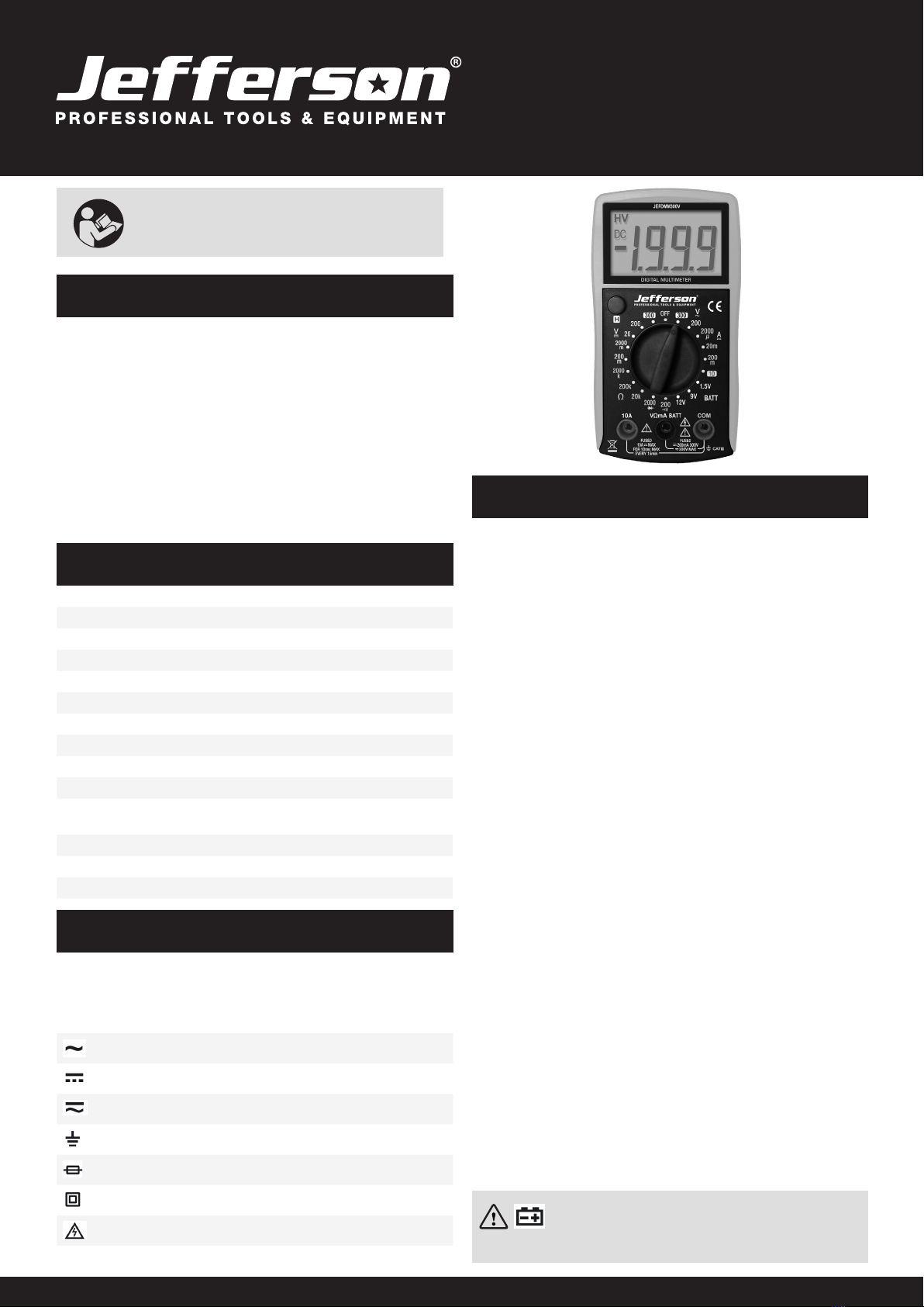
EQUIPMENT IDENTIFICATION
The table below describes the features numbered in the diagram shown to
the right:
1 LCD Display 3.5 Digits (Maximum reading 1999)
2 H Button: - Used to Enter / Exit “Data Hold” function
3 Function / Range Switch: - Used to select the required Function /
Range and turn the meter ON and OFF
4 10A Terminal: Plug in connector for the red test lead for current
measurements between 200mA - 10A
5 VΩmA Terminal: For all other measurements except current ≥
200mA
6 COM Terminal: Plug-in connector for the black test lead
MEASURING DC VOLTAGE
1. Connect the black test lead to the COM terminal and the red lead to the
VΩmA terminal.
2. Set the Function / Range switch to the desired range position. If the
magnitude of the voltage is not known before hand you can set the range
to the highest range rst and then reduce it range by range until a suitable
resolution is obtained.
3. Connect the test leads across the source or circuit to be tested.
4. Check the DC Voltage reading on the display. The polarity of the red test
lead connection will also be indicated.
Note: To avoid electric shock, personal injury or damage to the equipment
do not apply any voltage higher than the rated capacity of 300V between
the terminals
MEASURING AC VOLTAGE
1. Connect the black test lead to the COM terminal and the red lead to the
VΩmA terminal.
2. Set the Function / Range switch to the desired range position. If the
magnitude of the voltage is not known before hand you can set the range
to the highest range rst and then reduce it range by range until a suitable
resolution is obtained.
3. Connect the test leads across the source or circuit to be tested.
4. Check the AC Voltage reading on the display. The polarity of the red test
lead connection will also be indicated.
Note: To avoid electric shock, personal injury or damage to the equipment
do not apply any voltage higher than the rated capacity of 300V between
the terminals.
BATTERY TESTING
1. Connect the black test lead to the COM terminal and the red lead to the
VΩmA terminal.
2. Set the Function / Range switch to the corresponding BATT range
position.
3. Connect the red test lead to the positive terminal on the battery and the
black test lead to the negative battery terminal.
4. Check the working voltage of the battery on the display.
DC Voltage
AC Voltage
Battery Testing
JEFDMM300V
300V DIGITAL MULTIMETER
USER GUIDE
v.1.1
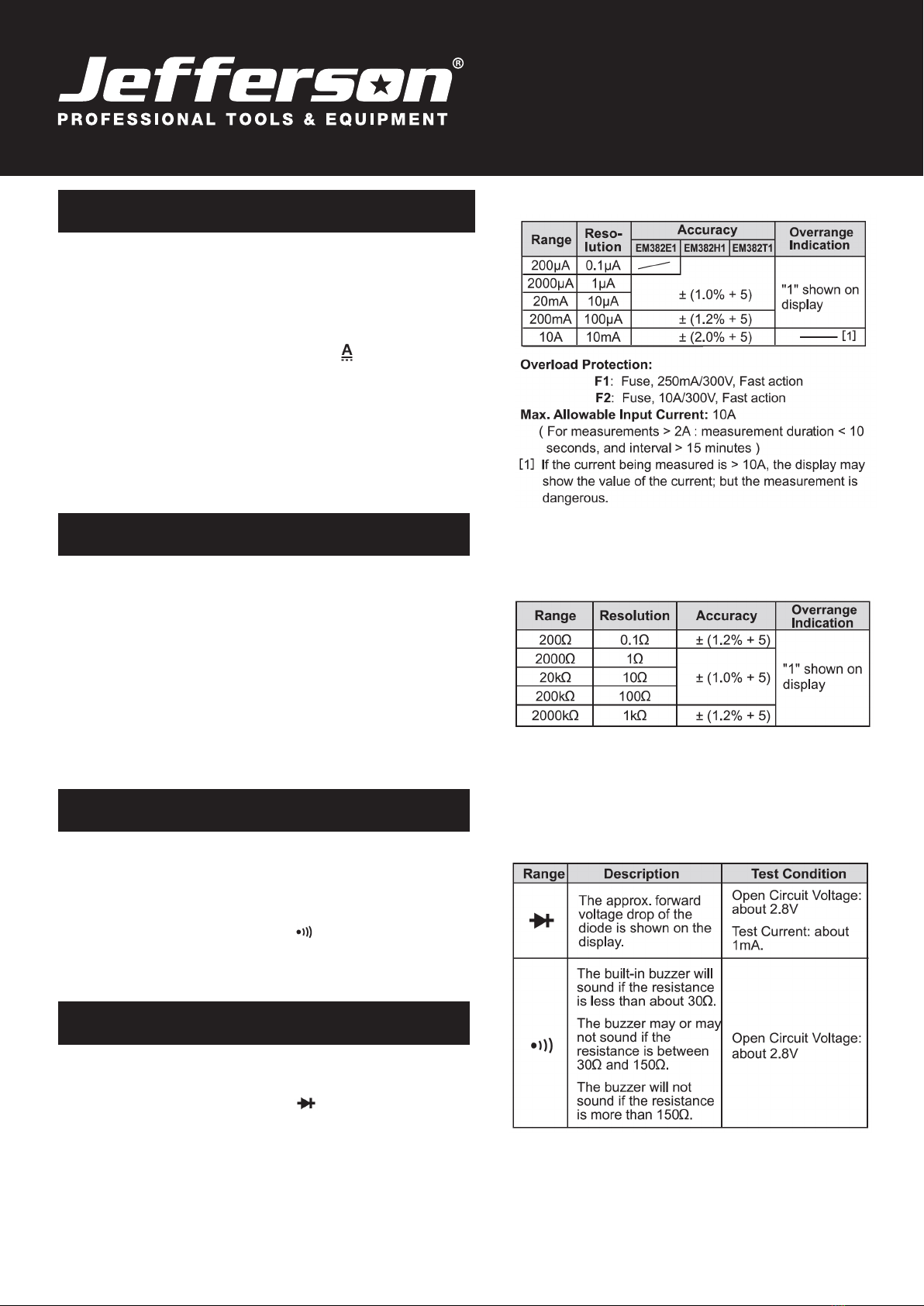
MEASURING DC CURRENT
1a. For current measurements less than 200mA:
Connect the black test lead to the COM terminal and the red lead to the
VΩmA terminal.
1b. For current measurements between 200mA and 10A:
Connect the black test lead to the COM terminal and the red lead to the
10A terminal.
2. Set the Function / Range switch to the desired range position. If the
magnitude of the current is not known before hand you can set the range
to the highest range rst and then reduce it range by range until a suitable
resolution is obtained.
3. Turn off the power to the circuit you need to measure then discharge all
capacitors of the circuit.
4. Break the circuit path to be measured and connect the test leads in
series with the circuit.
5. Check the DC Current reading on the display. The polarity of the red test
lead connection will also be indicated.
MEASURING RESISTANCE
Before measuring in-circuit resistance, disconnect all power to the circuit
to be tested and discharge all capacitors thoroughly.
1. Connect the black test lead to the COM terminal and the red lead to the
VΩmA terminal.
2. Set the Function / Range switch to the desired Ωrange position.
3. Connect the test leads across the equipment to be tested.
4. Check the resistance reading on the display.
Note: For measurements > 1000kΩ, the meter may take a few seconds
to stabilize the reading. This is normal for high resistance measurements.
When the input is not connected, i.e at open circuit, “1” will be displayed
as an over-range indication.
CONTINUITY TESTING
Before measuring the continuity, disconnect all power to the circuit to be
tested and discharge all capacitors thoroughly.
1. Connect the black test lead to the COM terminal and the red lead to the
VΩmA terminal.
2. Set the Function / Range switch to the setting.
3. Connect the test leads across the circuit to be measured.
4. If the resistance is lower than about 30Ω, the built in buzzer will sound.
DIODE TESTING
1. Connect the black test lead to the COM terminal and the red lead to the
VΩmA terminal. Note the polarity of the red test lead is positive “+”
2. Set the Function / Range switch to the setting.
3. Connect the red test lead to the anode of the diode to be tested and the
black test lead to the cathode of the diode.
4. The display will show the approximate forward voltage drop of the
diode. If the connection is reversed, then only the reading “1” will be
shown on the display.
Max Open Circuit Voltage: Approx 2.8V
DC Current
Resistance
Continuity & Diode Testing

LIMITED WARRANTY STATEMENT
Jefferson Professional Tools & Equipment ®, or hereafter "Jefferson" warrants its customers
that its products will be free of defects in workmanship or material. Jefferson shall, upon
suitable notification, correct any defects, by repair or replacement, of any parts or components
of this product that are determined by Jefferson to be faulty or defective. This warranty is void
if the equipment has been subjected to improper installation, storage, alteration, abnormal
operations, improper care, service or repair.
Warranty Period
Jefferson will assume both the parts and labour expense of correcting defects during the
stated warranty periods below. All warranty periods start from the date of purchase from an
authorised Jefferson dealer. If proof of purchase is unavailable from the end user, then the date
of purchase will be deemed to be 3 months after the initial sale to the distributor.
1 Year
• JEFDMM300V - 300V DIGITAL MULTIMETER
90 Days
• All replacement parts purchased outside of the warranty period
Important: All parts used in the repair or replacement of warranty covered equipment will be
subject to a minimum of 90 days cover or the remaining duration of the warranty period from
the original date of purchase.
Warranty Registration / Activation
You can register and activate your warranty by visiting the Jefferson Tools website using the
following address: www.jeffersontools.com/warranty and completing the online form. Online
warranty registration is recommended as it eliminates the need to provide proof of purchase
should a warranty claim be necessary.
Warranty Repair
Should Jefferson confirm the existence of any defect covered by this warranty the defect will
be corrected by repair or replacement at an authorized Jefferson dealer or repair centre.
Packaging & Freight Costs
The customer is responsible for the packaging of the equipment and making it ready for
collection. Jefferson will arrange collection and transportation of any equipment returned under
warranty. Upon inspection of the equipment, if no defect can be found or the equipment is not
covered under the terms of the Jefferson warranty, the customer will be liable for any labour
and return transportation costs incurred. These costs will be agreed with the customer before
the machine is returned.
NOTE: * Jefferson reserve the right to void any warranty for damages identified as being
caused through misuse *
Warranty Limitations
Jefferson will not accept responsibility or liability for repairs made by unauthorised technicians
or engineers. Jefferson's liability under this warranty will not exceed the cost of correcting the
defect of the Jefferson products. Jefferson will not be liable for incidental or consequential
damages (such as loss of business or hire of substitute equipment etc.) caused by the defect
or the time involved to correct the defect. This written warranty is the only express warranty
provided by Jefferson with respect to its products. Any warranties of merchantability are
limited to the duration of this limited warranty for the equipment involved.
Claiming Warranty Coverage
The end user must contact Jefferson Professional Tools & Equipment:
(Tel: +44 (0) 1244 646 048) or their nearest authorised Jefferson dealer where final
determination of the warranty coverage can be ascertained.
Step 1 - Reporting the Defect
Online Method:
Visit our website www.jeffersontools.com/warranty and complete the Warranty Returns form.
You can complete the form online and submit it to us directly or download the form to print out
and return by post.
Telephone Method:
Contact your Jefferson dealer or sales representative with the following information:
• Model number
• Serial number (usually located on the specification plate)
• Date of purchase
A Warranty Returns form will be sent to you for completion and return by post or fax, together
with details of your nearest authorised Jefferson repair centre. On receipt of this form Jefferson
will arrange to collect the equipment from you at the earliest convenience.
Step 2 - Returning the Equipment
It is the customer’s responsibility to ensure that the equipment is appropriately and securely
packaged for collection, together with a copy of the original proof of purchase. Please note
that Jefferson cannot assume any responsibility for any damage incurred to equipment during
transit. Any claims against a third party courier will be dealt with under the terms & conditions
of their road haulage association directives.
NOTE: Jefferson will be unable to collect or process any warranty requests without a copy of
the original proof of purchase.
Step 3 - Assessment and Repair
On receipt, the equipment will be assessed by an authorised Jefferson engineer and it will
be determined if the equipment is defective and in need of repair and any repairs needed are
covered by the warranty policy. In order to qualify for warranty cover all equipment presented
must have been used, serviced and maintained as instructed in the user manual. Where repair
is not covered by the warranty a quotation for repair, labour costs and return delivery will be
sent to the customer (normally within 7 working days).
Note: If the repair quotation is not accepted Jefferson Professional Tools & Equipment will
invoice 1 hour labour time at £30 per hour plus return carriage costs (plus VAT). In cases
where no fault can be found with the equipment, or, if incorrect operation of the equipment
is identified as the cause of the problem, a minimum of 1 hour labour at £30 per hour plus
carriage costs will be required before the equipment will be despatched back to the customer.
Any equipment repaired or replaced under warranty will normally be ready for shipment back to
the customer within 7 working days upon receipt of the equipment at an authorised Jefferson
Repair centre (subject to part availability). Where parts are not immediately available Jefferson
will contact you with a revised date for completion of the repair.
General Warranty Enquiries
For any further information relating to Jefferson warranty cover please call:
Disclaimer:
The information in this document is to the best of our knowledge true and accurate, but all
recommendations or suggestions are made without guarantee. Since the conditions of use
are beyond their control, Jefferson Professional Tools & Equipment ® disclaim any liability for
loss or damage suffered from the use of this data or suggestions. Furthermore, no liability is
accepted if use of any product in accordance with this data or suggestions infringes any patent.
Jefferson Professional Tools & Equipment ® reserve the right to change product specifications
and warranty statements without further notification. All images are for illustration purposes
only.
DECLARATION OF CONFORMITY
We, Jefferson Professional Tools & Equipment, as the authorised European Community
representative of the manufacturer, declare that this equipment conforms to the requirements of
the following standards:
IEC 61010 - Safety Requirements for Electrical Equipment for Measurement, Control, and
Laboratory Use
Signed by: Stephen McIntyre (Operations Director) Date: 13.01.20
www.jeffersontools.com
JEFDMM300V
300V DIGITAL MULTIMETER
USER GUIDE
v.1.1
MAINTENANCE & STORAGE
Note: Apart from replacing the fuse and battery, never attempt to service or repair this
equipment yourself. Contact Jefferson Tools for information and advice if a fault is detected.
NOTE: Ensure the equipment is turned off and that the test leads are disconnected before
carrying out any cleaning or maintenance on this multimeter.
• Periodically wipe the case with a slightly damp cloth a small quantity mild detergent. Do not
use abrasives or solvents to clean.
• Keep the buttons / terminals clean (carefully) using a cleaning swab dipped in alcohol as
required.
• Store the multimeter in a dry environment, away from devices emitting magnetic fields, when
not in use.
BATTERY AND FUSE REPLACEMENT
Replacing the Battery:
Change the battery immediately with a like-for-like replacement (1x 9V) as required when the
low-battery indicator is displayed. Do not use the meter when the indicator is displayed.
To replace the battery remove the screw on the battery cover, remove the old battery and insert
the replacement. Replace the battery cover and screw to secure.
Replacing the Fuses:
The fuses supplied with this equipment should rarely need to be replaced and any requirement
to replace them will usually be the result of misuse of the multimeter. To replace the fuse,
remove the screws on the backcover, remove the faulty fuse and replace with a similar size and
rated fuse. Reinstall the backcover and secure with the screws. This meter is supplied with two
Ø5 x 20mm fuses: F1 Fuse: 250mA / 300V, Fast action F2: Fuse: 10A / 300V, Fast action
Please note that the warranty for this item covers manufacturing defects.
The warranty does not cover overloading, normal wear and tear and
abuse. The warranty will become invalid if the casing is opened or
tampered with in any way.
Information on Disposal for Users of Waste Electrical & Electronic Equipment
(WEEE)]
This symbol on the product(s) and / or accompanying documents means
that used electrical and electronic products should not be mixed with
general household waste.
For proper treatment, recovery and recycling, please take this product(s)
to designated collection points where it will be accepted free of charge.
Jefferson Tools, Herons Way, Chester Business Park, Chester, United Kingdom, CH4 9QR,
Popular Multimeter manuals by other brands


Keithley
Keithley DMM6500 quick start guide

Elenco Electronics
Elenco Electronics M-1750 Operator's instruction manual

gefran
gefran 556 quick start guide

Gossen MetraWatt
Gossen MetraWatt METRAHIT ISO AERO Supplement to operating instructions

AEMC
AEMC SL206 user manual

Extech Instruments
Extech Instruments 450 user guide