4
4
4
4
.2.
.2.
.2.
.2.
AC
AC
AC
AC
voltage
voltage
voltage
voltage
measurement
measurement
measurement
measurement
1) Insert the black test lead to “ COM ” jack and the red one to “ V/ Ω/Hz ” jack.
2) Set the function switch to “ ” range.
3) The default range is Auto range, and "AUTO" is displayed. Pressing RANGE
key switch to manual range, 400mV/4V/40V / 400V/700V can be select ed
.
4) Connect the test leads to the test point, the voltage of the two points which
connected with the leads will appear on LCD.
4
4
4
4
.3
.3
.3
.3
DC
DC
DC
DC
Current
Current
Current
Current
measurement
measurement
measurement
measurement
1) Insert the BLACK test lead to “ COM ” jack and RED test lead to the “ mA ” (max .
400mA) or "10A" jack (max. 10A).
2 ) Set the FUNCTION switch to current range. Pressing “ ” key to select
DC measure method , connect the leads across to the tested circuit, the current
value and polarity the red lead connect with will appear on LCD.
Note:
Note:
Note:
Note:
1) If the current range is unknown beforehand, set the FUNCTION switch to a
high range and work down.
2) When only the figure " OL " is displayed over range is being indicated and the
FUNCTION switch must be set to a higher range.
3) The max input current is 400mA,or 10A depending upon the jack used.
Excessive current will blow the fuse.
4
4
4
4
.4.
.4.
.4.
.4.
AC
AC
AC
AC
current
current
current
current
measurement
measurement
measurement
measurement
1) Insert the BLACK test lead to “ COM ” jack and RED test lead to the mA ” (max.
400mA) or "10A" jack (max. 10A).
2 ) Set the FUNCTION switch to current range. Pressing “ ” key to select
AC measure method , connect the leads across to the tested circuit, the current
value will appear on LCD.
Note:
Note:
Note:
Note:
1) If the current range is unknown beforehand, set the FUNCTION switch to a high
range and work down.
2) When only the figure " OL " is displayed over range is being indicated and the
FUNCTION switch must be set to a higher range.
3) The max input current is 400mA,or 10A depending upon the jack used.
Excessive current will blow the fuse.
4
4
4
4
.5
.5
.5
.5
Resistance
Resistance
Resistance
Resistance
measurement
measurement
measurement
measurement
1) Connect the BLACK test lead to “ COM ” jack and RED test lead to the “ V/ Ω
/Hz ” jack.
2 ) Set the FUNCTION Switch to “ Ω” range.
3) Press "RANGE" to select Auto/Manual range
4) If measuring small resistance, should short test leads first, press "REL" once,
ensure measure value accuracy .
Note:
Note:
Note:
Note:
1)
To
use manual method, i f the resistance range is unknown beforehand, set the
FUNCTION switch to a higher range and work down.
2 ) If "OL" displays on LCD, it means over-range. When measuring resistance more
than 1M Ω, the meter may take a few seconds to stabilize. This is normal for
high resistance readings.
3) When the input is not connected, i.e. at open circuit, the figure " OL " will be
displayed for the over range condition.
4) When checking in-circuit resistance, be sure the power has been switched off
all
capacitors are fully discharged.
5 ) Do not input any voltage at this range.
4
4
4
4
.6
.6
.6
.6
Capacitance
Capacitance
Capacitance
Capacitance
measurement
measurement
measurement
measurement
1) Set the FUNCTION switch to " " position.
2) Press "REL" once to adjust to zero.
3 ) Connect the tested capacitor to “ COM ” , “ V/ Ω /Hz ” input sockets in
accordance to the leads (the polarity of the red lead is “ + ” ), the value will be
displayed on LCD.
4) When measuring more than 4uF, it takes 15 seconds to stabilize.
Note:
Note:
Note:
Note:
1) Capacitance range have only auto mode.
2) Before measuring each time, must press "REL" to ensure measure accuracy.
3) Units: 1uF=1000nF 1nF=10 00p F
4) Capacitors should be fully discharged to avoid damaging the meter.
4
4
4
4
.7
.7
.7
.7
Frequency
Frequency
Frequency
Frequency
measurement
measurement
measurement
measurement
1) Connect test leads or shield cable to "COM" and "V / Ω /Hz " jack.
2) Set the FUNCTION switch to the "Hz" range, and connect test leads or cable
across the source load under test.
3)
Press "Hz/Duty" to switch frequency/duty cycle, and display the reading of
frequency or duty cycle.
Note:
Note:
Note:
Note:
1) Frequency rang have only auto range mode.
2) Do not apply more than 250V DC/AC peak value to the input. Indication is
possible at voltage higher than 10V AC rms, but readings may be out of
specification.
3) In noisy environment, it is preferable to use shield cable for measuring small
signal.
4) Be caution to avoid contact with high tension circuits when measurement high
voltage.
4
4
4
4
.8
.8
.8
.8
hFE
hFE
hFE
hFE
measurement
measurement
measurement
measurement
1) Set the function switch to hFE range.
2 ) Define the transistor is NPN or PNP type, insert the emitter, base and collector
separately to the correct hole, the approx. value will be displayed on LCD.
4
4
4
4
.9
.9
.9
.9
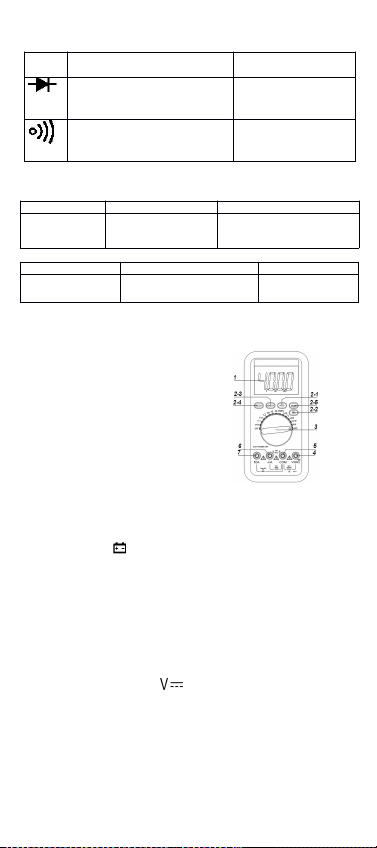
Diode
Diode
Diode
Diode
and
and
and
and
continuity
continuity
continuity
continuity
Test
Test
Test
Test
1) Connect the BLACK test lead to “ COM ” jack and RED test lead to the “ V ΩHz ”
jack..
2 ) Set the FUNCTION switch to “ ” position. Press " DC/AC " key which
select diode measure method.
3) Forward measure: Connect RED test lead to the positive of the test diode,
BLACK test lead to the negative, then, reading of approx. forward voltage of
this diode displays.
4) Reverse measure: Connect BLACK test lead to the positive of the test diode,
RED test lead to the negative, the mark "OL" will be displayed.
5) Proper diode testing should include both steps.
6) Press " " to select continuity mode.
7) Connect the test probes to two points of circuit, if the resistance is lower than
approx. 50 ±20 Ω
.
Buzzer sounds.
Note:
Note:
Note:
Note:
Do not input voltage at this range.
4
4
4
4
.10
.10
.10
.10
Temperature
Temperature
Temperature
Temperature
measurement
measurement
measurement
measurement
1.
Set the function key to “ ℃ ” range.
2.
Insert the cold-point of the thermocouple to “ K TEMP ” hole, and the work-point
to the place wanted to take temperature, the value will be displayed on LCD.
NOTE:
NOTE:
NOTE:
NOTE:
1.
When the input terminal is in open circuit, will display the “ normal temp. ”
2.
Do not change the thermocouple, or, the accuracy can not be secured.
3.
Do not input voltage at this range.
4
4
4
4
.1
.1
.1
.1
1
1
1
1
Data
Data
Data
Data
hold
hold
hold
hold
Press “ Hold ” key, the current data will display on LCD; Press the key again, will
cancel the hold function.
4.
4.
4.
4.
1
1
1
1
2
2
2
2
Auto
Auto
Auto
Auto
power
power
power
power
off
off
off
off
1) Stop w orking for 15mins, the instrument is auto off and into the sleep mode. The
buzzer will sound before power
off.
Press any key to turn on the power.
2 ) Pressing “ ” key before turning on can cancel the function.
5
5
5
5
.
.
.
.
WARNING
WARNING
WARNING
WARNING
1) When measuring voltage ensure that instrument is not connected or switched to a
current or resistance range, or to the diode check. Always ensure that the correct
terminals are used for the type of measurement to be made.
2) Take extreme care when measuring voltage above
50V,
especially from sources
where high energy is existed.
3) Avoid making connections to “ live ” circuits whenever possible.
4) When making current measurements ensure that the circuit not “ live ” before
opening it in order to connect the test leads.
5) Before making resistance measurements or diode test, ensure that the circuit
under test is de-energized.
6) Always ensure that the correct function and range is selected. If in doubt about
the correct range to use, start with the highest and work downwards.
7) Extreme care should be taken when using the instrument to conjunction with a
current transformer connected to the terminals if an open circuit occurs.
8) Ensure that the test leads and probes are good condition with no damage to the
insulation.
9) Take care not to exceed the over-load limits as given in the specification.
10) FUSE FOR REPLACEMENT MUST BE OF THE CORRECT TYPE AND
RATING.
11) Before opening the case of the instrument to replace battery or fuse, disconnect
the test leads from any external circuit, set the selector switch to “ OFF ” position.
6
6
6
6
.
.
.
.
MAINTENANCE
MAINTENANCE
MAINTENANCE
MAINTENANCE
Do not try to modify the inner circuit.
1) Keep the multime t er
dry.
Keep the multi-meter away from dust and dirt
2) Use and store the multi-meter only in normal temperature environments.
Temperature extremes can shorten the life of electronic devices, damage batteries ,
and distort or melt plastic part.
3) Handle the multi meter gently and carefully. Dropping it can damage the circuit
boards and case and can cause the multi-meter to work improperly although the
holster can provide enough protection.
4) Wipe the multi-meter with a damp cloth occasionally to keep it looking
new.
Do
not use harsh chemicals, cleaning solvents, or strong detergents to clean the
multi-meter.
5) Take out off the battery if do not use for a long time. When LCD displays “ ” , the battery should be replaced.
a.
Ensure the instrument is not connected to any external circuit. Set the selector
switch to
OFF position and remove the test leads from terminals.
b.
Remove the screw on the bottom case and lift the bottom case.
c.
Remove the spent battery and replace it with a battery of the same type.
6) Replace the fuse with same type and rating as the replacements.
NOTE:
NOTE:
NOTE:
NOTE:
1) Do not input a voltage over 1000V DC/AC peak value.
2 ) Do not measure voltage at current range, resistance range, diode and buzzer
range.
3 ) Do not use the meter if the battery is not replaced well or the battery case is not
fixed.
4 ) Before replacing battery or fuse, release the test leads from the test point and
turn power
off.
MB-VC97-62