operating in the 0 to 400μF full-scale manual range
reduces the full-scale range to 0 to 40μF (and improves
measurement resolution). The next press of the button
reduces the range to 0 to 4μF. When the smallest full-
scale range has been reached, the next press of the
RANGE
button switches the meter back to the largest full-
scale manual range for the parameter being measured.
To exit Manual Ranging mode
and return to Auto Ranging
mode, press and hold the
RANGE
button.
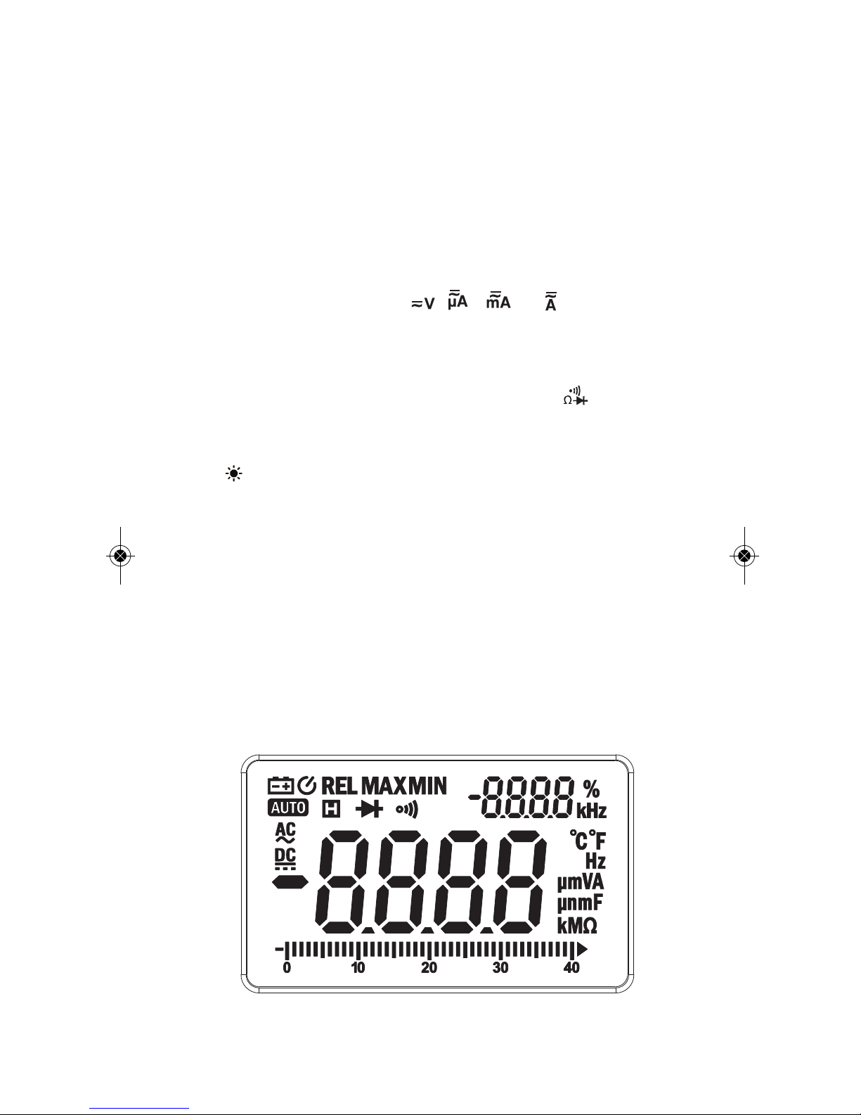
Holding Readings
Pressing the
HOLD
button “freezes” the values on both
the primary and secondary readouts and causes an
icon to appear at the top left of the LCD. Pressing the
button again releases the hold and removes the icon.
While readings are held, the analog bar graph at the
bottom of the LCD continues to track real-time readings
of the parameter being measured.
Tracking Maximum and Minimum Readings
Pressing the
MAX/MIN
button once switches the
secondary readout to show the
largest
value of the
parameter being measured since entering that
measurement mode. The primary display and the analog
bar graph at the bottom of the LCD will continue to show
real-time readings.
Pressing the
MAX/MIN
button a second time switches the
secondary readout to show the
smallest
value of the
parameter being measured since entering that
measurement mode. The primary display and the analog
bar graph at the bottom of the LCD will continue to show
real-time readings.
Pressing the
MAX/MIN
button a third time resumes
“normal” display operation, with different values in the
primary and secondary readouts.
When the
MAX/MIN
button is pressed, the meter will
automatically exit Auto Ranging mode and enter Manual
Ranging mode using the full-scale range in effect at that
moment.
Making Relative Measurements
Pressing the
REL⌬
button during measurement of
current, voltage, resistance or capacitance freezes the
value being measured at that instant on the secondary