JEHNERT SOUND DESIGN 46129 User manual

SoundSound
D E S I G N
JEHNERT
Golf IV / Variant / Bora
4-türig
Garantie
2000/by.aj/FH - 15 -
Montageanleitung
Montageanl.Art. 46129/FH11.00
Artikel-Nr. 46129 4-türig
Jehnert Sound Design
Entwicklung und
Produktion von
Car-Audio-Systemen
Heinrich-Hertz-Str. 11
70794 Filderstadt
Tel.: 0711-77 97 87- 87
Fax: 0711-77 78 921
www.jehnert.com
Als Hersteller übernehmen wir für diese Türpaneele bzw. Soundsystem eine
Garantie für 2 Jahre, gerechnet ab dem Kaufdatum beim Händler.
Innerhalb dieser Garantiezeit beheben wir nach unserer Wahl durch Reparatur
oder Austausch unentgeltlich alle Mängel, die auf Material- oder Herstellungs-
fehlern beruhen.
Von der Garantie ausgenommen sind Schäden, die auf unsachgemäßen Gebrauch,
auf Verschleiß oder auf Eingriffe durch Dritte zurückzuführen sind. Die Garantie
umfasst keine Folgeschäden und auch nicht diejenigen Mängel, die den
Wert oder die Gebrauchstauglichkeit der Paneele / Soundsystem nur unerheblich
beeinträchtigen. Eine Garantiepflicht wird nicht ausgelöst bei Schäden die durch
äußere Einwirkungen verursacht wurden.
Vom Umtausch ausgeschlossen sind Paneele mit zusätzlichen oder falschen
Montagebohrlöcher. Dies sind Beschädigungen am Paneel, die nicht wieder
Instand gesetzt werden können.
☞
development and production
of car-audio-systems
Porsche Str. 15
70794 Filderstadt
phone 0 71 58 / 9 56 99-0
fax 0 71 58 / 9 56 99-10
e-mail: [email protected]
www.jehnert.com
Installation instruction
4-doors
4-doors
part-no.

Packliste .............................................................................. 2
1. Demontage der Türverkleidung............................................... 3
2. Montage des Hochtöners im Original-Spiegeldreieck ............... 4
3. Paneelanpassung / Fixpunkte ................................................. 5
4. Bearbeiten der Türverkleidung / Montage der Türpaneele.......... 6
5. Lautsprecherleitungen ........... ............................................... 7
6. Dämmung der Türverkleidung ............................................... 8
7. Montage der Türverkleidung auf die Fahrzeugtüren ................. 9
8. Frequenzweichenmontage + Lautsprecheranschluss ................. 10
Lautsprecheranschluss - Schaltbild ........................................ 11
9. Montage der Lautsprecher-Abdeckblenden ............................. 12
Technische Informationen ..................................................... 13
Service / Fehlersuche............................................................. 14
Garantie ............................................................................. 15
Seite
46129 - Golf IV “4türig”- 14 - © JEHNERT SOUND DESIGN46129 - Golf IV “4-türig”- 1 - © JEHNERT SOUND DESIGN
Technische Fragen: Info-Hotline: 0711 - 77 97 87 - 87
Wir danken für Ihre Unterstützung !
Mirko Schwarz
Produktentwicklung / Qualität
Durchwahl: - 67
Wir helfen Ihnen gerne weiter!
Sehr geehrter Kunde,
Wir haben uns sehr bemüht unsere neuen Montageanleitungen ausführlicher und
“Schritt für Schritt”zu erklären.
Ihre Tipps und Anregungen helfen uns künftige Unklarheiten oder Fehlinter-
pretationen weiter auszuschließen.
Teilen Sie uns deshalb mit, was Ihnen nicht gefällt oder was wir noch ändern sollten.
Steffen Kretzschmar
Sattlerei / Produktionsablauf
Durchwahl: - 69
Marc Sitter
Versand / Service
Durchwahl: - 68
Marc Sitter
Versand / Service
Durchwahl: - 68
Die folgenden Hinweise sollen Ihnen dabei helfen, Fehler oder Störungen selbst zu
beheben. Wenn folgende Abhilfemaßnahmen nicht greifen, rufen Sie uns bitte an:
Was kann es sein ... mögliche Ursache / Lösung
wenn’s nicht richtig klingt Tieftöner verpolt ( Seite 10)
Frequenzweichen falsch angeschlossen ( Seite 11)
Türverkleidung und Regenschutzfolie
nicht ausgeschnitten ( Seite 9)
Verstärker zu wenig Leistung ( Seite 13)
Verstärker-Anschluss
wenn’s nicht richtig passt Fixpunkte Türpaneelanpassung ( Seite 5)
Montage der Paneele auf die TV ( Seite 9)
Abdeckungen nicht haften Hinweise Seite 12 beachten!
Vibrationsgeräusche Dämmung s. Hinweise Seite 8
Selbsthilfe und Fehlersuche
Inhaltsverzeichnis
Besonders wichtige Hinweise enthalten folgende Markierung:
☞
Bitte folgen Sie den Anweisungen der Montageanleitung
“Schritt für Schritt”
und prüfen Sie den Packungsinhalt
Contents
Packing list page
1. Disassembly of the door lining 3
2. Installation tweeter 4
3. Paneel alignment / reference points 5
4. Handling of door lining / panel installation - fastening 6
5. Loudspeaker cables 7
6. Insulation of the door lining / car door 8
7. Installation of the door lining 9
8. Installation crossover + speaker connection 10
Loudspeaker wiring diagram 11
9. Installation of the speaker-grills 12
Technical information 13
Service / fault diagnoses 14
Guarantee 15
Please follow the installation instructions
“step by step“
and check the package contents
Particularly important notes contain the following remarks:

Verpackungseinheit Checkliste
Türpaneele, bezogen (rechts / links)
Abdeck-Blenden, bezogen (rechts / links)
Hochtöner 26 mm (Montage mit Heißkleber /Silikon)
Mitteltöner 100 mm Q (jeweils mit 4 Blechschrauben am Paneel montiert)
Tieftöner 160 mm (jeweils mit 2 Blechschrauben am Paneel montiert)
Frequenzweichen (rechts / links)
Kleinteile-Beutel:
Schrauben-Senkkopf, M 4 x 30
Schrauben-Senkkopf, M 4 x 40
Schrauben-Senkkopf, M 4 x 50
Schrauben-Senkkopf, M 4 x 60
6-Ktn.Mutter M 4
Unterlagscheiben Ø12mm
Unterlagscheiben Ø20mm als Distanzhilfe für Klettverschlüsse
Blechschrauben, schwarz 3,9x13 (16xf. TT)
Klettband à2,5 cm (Reserve)
Kleinteile-bereits montiert:
Klettverschlüsse + Klettband
Blechschrauben, schwarz 3,9 x 16 f. TT
Blechschrauben, schwarz 3,5 x 16 f. MT
Schrauben-Senkkopf, M 4 x 40
Die Ware wurde sorgfältig verpackt und auf ihre Vollständigkeit geprüft. Bei Fehlmengen, Schäden oder Mängel
beachten Sie bitte unsere Garantieleistungen auf der Rückseite dieser Montageanleitung.
Packliste 46129
46129 - Golf IV “4türig”- 2 - © JEHNERT SOUND DESIGN
2
2
2
2
4
2
6
2
4
2
18
18
2
8
2
je 10
8
8
4
46129 - Golf IV “4türig”- 13 - © JEHNERT SOUND DESIGN
Technische Information
Fahrzeugausstattung: elektrische Fensterheber
Modell/ Modelljahr: 4-türig
Dämmung der Türen: zusätzliche Dämmung der Fahrzeugtüren wird
empfohlen - siehe Seite 8
Einstell-Hinweis: Um den optimalen Raumklang zu erzielen,
sollten am Radiogerät sämltiche Einstellungen
(Bass,Höhen, Loudness usw.) auf Null bzw.
neutral eingestellt werden
empfohlene
Verstärkerleistung: ab 2x 100 - 200 Watt sinus / 2 Ohm
Blechschneidearbeiten: entfallen
Lautsprecherausschnitte/ 2 x 144mm (max.AußenmaßTieftöner 165 mm)
pro Seite (max.Einbautiefe Tieftöner 70 mm)
DIN-Euro-Norm-Korb passend
1 x 92mm (max.AußenmaßMitteltöner 100 mm)
(max.Einbautiefe Mitteltöner 60 mm)
Sound-System: 3-Wege
2 x 160 mm Tieftöner / Seite
1 x 100 mm Mitteltöner / Seite
1 x 26 mm Hochtöner / Seite
fahrzeugspezifische Frequenzweiche
Belastbarkeit Dauer / Musik: 2 x 150/200Watt
Übertragungsbereich: 35-22.000 Hz
Impedanz: 2 Ohm
Änderungen, die dem technischen Fortschritt dienen, bleiben vorbehalten.
Contents
Packing list check list
hardware bag
preassembled hardware:
doorboards, covered (right / left)
Speaker grill, covered (right / left)
tweeter 26 mm
midrange 100 mm (each mounted on the panel with 4 Sheet metal-screws)
woofer 160 mm (each mounted on the panel with 2 Sheet metal-screws)
Crossover (links / rechts)
at head screws, M4 x 30
at head screws, M4 x 40
at head screws, M4 x 40
at head screws, M4 x 50
at head screws, M4 x 60
hex nut M 4
washer Ø 12 mm
washer Ø 20mm as spacer for Velcro fastener
sheet metal screw 3,9 x 13
Velcro strip à 2,5 cm (reserve)
Velcro fastener plus strips
Sheet metal screws, black 3,9 x 16 (for woofer)
Sheet metal screws, black 3,5 x 13 (for midrange)
The product was carefully packed and checked for its completeness. If you nd anything missing, damaged or
defective, please notice our guarantee services on the back of these assembly instructions.

Abb. Fahrerseite
A
C1
D1D2D3
D4
C2C3
Abnehmen der Abdeckblenden:
Die Abdeckblenden können durch vorsichtiges Lösen der Klettverschlüsse
jederzeit abgenommen werden.
VORSICHT:
Bitte jede Art von »gewaltsamem Reißen «an den Blenden
vermeiden (Bruchgefahr !)
1.1. Türverkleidung - Fahrerseite
1.1.1. Fensterscheibe komplett herunterlassen.
1.1.2. Blende (A) in der Innenseite des Türgriffes weghebeln.
1.1.3. Kompletter Türgriff mit Schalterleiste von unten nach nach oben aus der
Verrasterung abdrücken. Darunterliegende 3 Kreutzkopf-Schrauben (C) entfernen.
1.1.4. Torx-Schrauben (D1-3) an der Türverkleidungsunterkante und Torx-Schraube
(D4) an der Türverkleidungsinnenseite entfernen.
1.1.5. Türverkleidung an den unteren und seitlichen Türverkleidungsrändern vorsichtig
(Bruchgefahr!) von den Plastikklipsen abdrücken.
1.1.6. Türverkleidung oben an der Abdichtleiste aus den Klammern herausheben und
gleichzeitig vom Türinnenblech nach oben wegziehen.
1.1.7. Türentriegelungsbautenzug aushängen und alle elektrischen Anschlüsse abstecken.
1.1.8. werkseitiger Lautsprecher demontieren ( wird nicht mehr verwendet)
2.2. Türverkleidung - Beifahrerseite:
2.1.1. Fensterscheibe komplett herunterlassen.
2.2.2. Türgriff-Blende (A1) von unten weghebeln und darunterliegende
2 Kreutzkopf-Schrauben (F1+2) entfernen.
2.2.3. Alle 4 Torx-Schrauben (D1-4) an der Türverkleidungsunterkante und Torx-Schraube
(E) an der Türverkleidungsinnenseite enfernen.
2.2.4. siehe Fahrerseite 1.1.5. - 1.1.8.
46129 - Golf IV “4türig”- 3 - © JEHNERT SOUND DESIGN
46129 - Golf IV “4türig”- 12 - © JEHNERT SOUND DESIGN
1 . Demontage der Türverkleidung:
A1
F1
F2
Die Klettverschlüsse sind ab Werk bereits komplett auf den Abdeckblenden
montiert.
WICHTIG :
Die Klettverschlüsse haften sehr stark!
Die Abdeckblenden deshalb erst nach kompletter Montage der Türpaneele
und Soundsystem fest aufdrücken !
Tipp:
... wenn sich die Abdeckblende an manchen Stellen nicht auf dem
Paneel festdrücken läßt ...
Ursache: Die besondere Formgebung der Türpaneele an dieser Stelle
und die daraus resultierende unterschiedliche Materialstärken
der Abdeckblenden.
Lösung: Mit einer M 4-Unterlagscheibe ø20mm (3) unter dem
Klett-Teller wird dieser Abstand einfach und schnell ausgeglichen:
9. Abdeckblenden
☞
☞
☞
Abdeckblende
2 selbstklebendes Klettband
1 Klett-Druckverschluss
3 Unterlagscheibe M4 ø20 als Distanzhilfe
Türpaneel
Abb. Beifahrerseite
1. Disassembly of the door lining
1.1. Roll down window completly.
1.2. Remove cover of door handle (inner side- A).
1.3. Push the complete door handle with switch board and pull away upward.
Remove the underneath 3 crosshead screws (C).
1.4. Unscrew the 3 Torx- screws (D1-3) on the lower edge of the door lining and the
Torx screw (D4) on the inner side of the door lining.
1.5. Carefully remove the plastic pins of the door lining edges and pull the door lining away
upward unplug power cable for the switch board.
2.1. Remove cover of door handle (A1) and unscrew the 2 crosshead screws ( F1+2)
underneath.
2.2. Unscrew the 3 Torx- screws (D1-4) on the lower edge of the door lining and the
Torx screw (E) on the inner side of the door lining.
2.3. Carefully remove the plastic pins of the door lining edges and pull the door lining
away upwards.
1. door lining driver‘s side:
2. door lining co-driver‘s side:
g. driver‘s side
g. co-driver‘s side

Lautsprecheranschluss - Schaltbild
Alle Lautsprecher und Frequenzweichen anschließen:
H
i
g
h
P
e
r
f
o
r
m
a
n
c
e
D E S I G N
JEHNERT
SoundSound
Midrange
Speaker
MADE IN GERMANY
2.1. Demontage des Hochton-Spiegeldreieckes:
2.1.1. Nach der Demontage der Türverkleidung, Schraube (A) unterhalb dem
Hochtonspiegeldreieck entfernen.
2.1.2. Komplette Abdeckblende des Hochton-Spiegeldreieckes nach vorne abziehen.
2.2. Bearbeitung der Hochton-Spiegeldreieck-Abdeckblende:
2.2.1. Auf der Rückseite der Abdeckblende, die Laschen vom Lautsprecher-
Abdeckgitter (B) geradebiegen und Gitter abziehen.
2.2.2. Original-Hochtöner aus der Verrasterung herausdrücken.
2.2.3. Hochtöner-Öffnung (C) auf das Außenmaßdes “Jehnert-Hochtöners”
mit einem Rundschleifer/Dremel vergrößern.
2.2.4. Lautsprecher-Abdeckgitter wieder anbringen und Laschen wieder umbiegen.
2.3. Montage des Hochtöners:
2.3.1. Hochtöner vorverkabeln (dabei Kabellänge bis zur Weiche im Türpaneel abmessen)
2.3.2. Hochtöner am Original-Montageort in das Schaum-Formteil des Spiegel-
dreieckes einsetzen und mit Heißkleber oder Silikon fixieren.
2.3.3. Hochton-Spiegeldreieck-Abdeckblende wieder aufstecken und festschrauben.
Verstärker
100-200 Watt RMS / 2 Ohm
empf.Leistung
46129 - Golf IV “4türig”- 11 - © JEHNERT SOUND DESIGN
2.Montage des Hochtöners im Original-Hochton-Spiegeldreieck
46129 - Golf IV “4türig”- 4 - © JEHNERT SOUND DESIGN
Schaltbild 3-Wege Frequenzweiche / 2x Tieftöner
H
i
g
h
P
e
r
f
o
r
m
a
n
c
e
D E S I G N
JEHNERT
SoundSound
WOOFER
Speaker
MADE IN GERMANY
HochtönerTieftöner
SoundSound
D E S I G N
JEHNERT
MitteltönerEingang
3-Wege fahrzeugspezifische Frequenzweiche
Golf IV
H
i
g
h
P
e
r
f
o
r
m
a
n
c
e
D E S I G N
JEHNERT
SoundSound
Tweeter
Speaker
MADE IN GERMANY
Achtung:
2 Ohm-System!
Blende des Hochton-
Spiegeldreieckes
B= Lautsprecher-Abdeckgitter
C= Original-Öffnung für Hochtöner
A
H
i
g
h
P
e
r
f
o
r
m
a
n
c
e
D E S I G N
JEHNERT
SoundSound
WOOFER
Speaker
MADE IN GERMANY
2. Installation of tweeter in standard mirrow triangle
2.2.1. Straighten the cover plates of the speaker`s grill on the backside of the grill and
remove the grill.
2.2.3 Enlarge the tweeter cut-out (C) to the size of the JEHNERT-tweeter
(use a plain grinder).
2.2.4. Reinstall the speaker’s grill and rebend the cover plates.
2.3.1. Pre-cable the tweeter (measure up length of cable up to the crossover in the
door build).
2.3.2. Insert the tweeter into the original mount (foamed part of the mirror triangle) and afx it
with hot melt adhesive.
2.3.3. Reinstall the grill of the mirror triangle and tighten with screws.
2.1.1. After having disassembled the door lining, remove screw ( A) underneath the mirror
triangle.
2.1.2. Lever off the complete grill of the mirror triangle and pull away upward.
2.1. disassembly of mirror triangle for tweeter
2.2. work the grill of tweeter mirror triangle
2.3. installation of tweeter:
Loudspeaker wiring diagram
Connect all loudspeakers and crossover circuits:
wiring diagramm 3-way-system with add. subwoofer-system:
H
i
g
h
P
e
r
f
o
r
m
a
n
c
e
D E S I G N
JEHNERT
SoundSound
Midrange
Speaker
MADE IN GERMANY
2.1. disassembly of mirror triangle for tweeter
2.1.1. after having disassembled the door lining, remove screw ( A) underneath the mirror triangle
2.1.2. Lever off the complete grill of the mirror triangle and pull away upward
2.2. work the grill of tweeter mirror triangle
2.2.1. straighten the cover plates of the speaker`s grill on the backside of the grill and
remove the grill
2.2.3 enlarge the tweeter cut-out (C) to the size of the JEHNERT –tweeter (use a plain grinder)
2.2.4. reinstall the speaker’s grill and rebend the cover plates.
2.3. installation of tweeter:
2.3.1. pre-cable the tweeter ( measure up length of cable up to the crossover in the door build)
2.3.2. insert the tweeter into the original mount (foamed part of the mirror triangle)
and affix it with hot melt adhesive.
2.3.3. reinstall the grill of the mirror triangle and tighten with screws
H
i
g
h
P
e
r
f
o
r
m
a
n
c
e
D E S I G N
JEHNERT
SoundSound
Tweeter
Speaker
MADE IN GERMANY
75129 - Golf IV “2-doors”- 11 - © JEHNERT SOUND DESIGN
H
i
g
h
P
e
r
f
o
r
m
a
n
c
e
D E S I G N
JEHNERT
SoundSound
WOOFER
Speaker
MADE IN GERMANY
H
i
g
h
P
e
r
f
o
r
m
a
n
c
e
D E S I G N
JEHNERT
SoundSound
WOOFER
Speaker
MADE IN GERMANY
H
i
g
h
P
e
r
f
o
r
m
a
n
c
e
D E S I G N
JEHNERT
SoundSound
WOOFER
Speaker
MADE IN GERMANY
2 . Installation of tweeter in standard mirrow triangle
75129 - Golf IV “2-doors”- 4 - © JEHNERT SOUND DESIGN
H
i
g
h
P
e
r
f
o
r
m
a
n
c
e
D E S I G N
JEHNERT
SoundSound
WOOFER
Speaker
MADE IN GERMANY
tweetersubwoofer
SoundSound
D E S I G N
JEHNERT
midrangeinput
3-way crossover circuit
Golf IV 75129
subwoofer
SoundSound
D E S I G N
JEHNERT
input
3-way subwoofer crossover circuit
Golf IV Subwoofer-
crossover circuit
grill of mirror
triangle for tweeter
B= speaker grill
C= original tweeter cut-out
A
double-woofer -
front of the door build
amplifier
=
set of cables supplied with
from 200 Watt RMS
double-woofer -
rear of the door build

8. Frequenzweichenmontage + Lautsprecheranschluss
8.1. Frequenzweichen vorverkabeln - vgl. Abb. Seite 11.
8.2. Frequenzweiche im Hohlraum zwischen Türpaneel und Türverkleidung
(siehe Abb.) einsetzen und befestigen.
WICHTIG: Platine vor Feuchtigkeit schützen und darauf achten,
dass die Platine nicht an Metallteilen anliegt - Kurzschlussgefahr !
8.3. Tief- und Mitteltöner einsetzen und alle Lautsprecher mit der
Frequenzweiche verkabeln (Paralell-Schaltung):
Hinweis: Bevor alle Tieftöner an die Frequenzweiche angeschlossen werden,
sollte die Polarität aller Tieftöner an einer 9 Volt-Batterie
überprüft werden:
Pol des FW-Eingang an von 9 V Batterie
Pol des FW-Eingang an von 9 V Batterie
Alle Tieftöner müssen bei dieser Überprüfung gleichmäßig ausschwingen!
Ein verpolter Tieftöner kann die gesamte Basswiedergabe
aufheben!
Fixpunktlinie 2
(Linie 2
ralell zu
Fixpunktlinie 4:
Abstand gerade Paneelseiten-
kante zur Designlinie der
Türverkleidung = etwa12mm
Fixpunktlinie 3:
Abstand schräge Paneelseiten-
kante zur Designlinie der
Türverkleidung = etwa 5mm
Fixpunktlinie 1
3.1. Türverkleidung auf eine ebene Fläche legen.
3.2. Die auf dem Paneel zur Transportsicherung befestigten Lautsprecher
demontieren (Schrauben zur späteren Montage aufbewahren).
3.3. Das Paneel ohne Lautsprecher auf die Türverkleidung legen und ausrichten:
Fixpunktlinien zur Anpassung:
Nur die exakte Anpassung des Paneeles auf die Türverkleidung
gewährleistet eine optimale Passgenauigkeit
1. Die Oberkante des Paneels paralell zur Linie (1) der Türverkleidung und
zur Türverkleidungsunterkante (Linie 2) anpassen.
2. Darauf achten, daßdie vordere Seitenkante vom Paneel paralell zur
Designlinie der Türverkleidung läuft (Linie 3+4):
2.1. Abstand zwischen
schräger
Seitenkante des Paneels und Designlinie
der Türverkleidung etwa ca. 5mm (Linie 3)
2.2. Abstand zwischen
geraden
Seitenkante des Paneels und Designlinie
der Türverkleidung etwa 12mm (Linie 4).
46129 - Golf IV “4türig”- 10 - © JEHNERT SOUND DESIGN
46129 - Golf IV “4türig”- 5- © JEHNERT SOUND DESIGN
3.Paneelanpassung
�
�
Hochtöner
Tieftöner
SoundSound
DESIG N
JEHNERT
Mitteltöner
Eingang
3-Wege fahrzeugspezifischeFrequenzweiche
Golf I V
✚ ✚
7. Installation of the door lining onto car door
7.1. Put in the door lining in the sealing above.
7.2. Fit the door lining in contrary order (described on page 3).
7.3. carefully screw in the sheet metal screws through the door build
and the door lining (Spax 5,0 x 100)
7.4. cut out the moisture protection foil (u-form) and stabilize the lateral cutting
edges in order to avoid vibration noise (e.g. use a packing tape)
e 2) an
ll zur D
reference line 2:
(Linie 2
ralell zu
reference line 4:
distance between straight lateral
edge of the door build and design
line of the door lining = about 12mm
reference line 3:
distance between angled lateral
edge of the door build and design
line of the door lining = about 5mm
reference line 1:
4.1. Place the door lining on a plane surface.
4.2. Dismount the loudspeakers attached to the panel for transport protection.
Retain the screws for later assembly.
4.3. Place the panel without loudspeakers and grill on the door lining and align it:
Reference points for fitting:
Only precise alignment of the panel with the door
lining warrants optimal fit.
4.4. align the upper panel edge parallel (ref.point line 1) to the lower edge of the
door-lining (ref.point line 2)
4.5. please observe: front lateral panel edge has to be parallel to the design line
of the door lining (ref.point line 3 and 4)
4.5.1. the distance between angled lateral edge of the door build and design line
of the door lining is about 5mm (ref.point line 3)
4.5.2. the distance between straight lateral edge of the door build and design line
of the door- lining is about 12mm (ref.point line 4)
75129 - Golf IV “2-doors”- 6 - © JEHNERT SOUND DESIGN
4 . Panel alignment
75129 - Golf IV “2-doors”- 9 - © JEHNERT SOUND DESIGN
Spax 5,0 x 100
Spax 5,0 x 100
☞
1 =
M 4 x 30
8 =
M 4 x 40
9 =
M 4 x 40 5 =
M 4 x 30
2 =
M 4 x 60
3 =
M 4 x 50
4 =
M 4 x 50
6 =
M 4 x 30
7 =
M 4 x 40
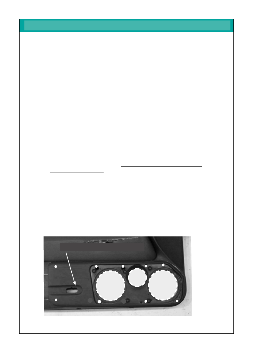
Ausschnitt
Tieftöner
“vergrößern”
Ausschnitt
Mitteltöner
Ausschnitt
Tieftöner
7. Montage der Türverkleidung auf die Fahrzeugtüren
7.1. Zum Schutz gegen Nässe und Beschädigung der Lautsprecher durch
Feuchtigkeit:
Regenschutzfolie (handelsübliche Plastikfolie / Sack) in Größe
der Aussparung hinter dem werkseitigen Lautsprecher, auf dem Türblech
z.B. mit Sprühkleber / Klebeband nachträglich anbringen.
7.2. Türverkleidung oben in die Türschachtleiste einhängen
7.3. In umgekehrter Reihenfolge wie auf Seite 3 beschrieben wieder befestigen.
7.4. Zur Steigerung des Klangvolumens die nachgerüstete Regenschutzfolie
hinter den Lautsprecheröffnungen entweder nur unten oder
u-förmig einschneiden.
Bei u-förmigem Ausschnitt: Seitliche Schnittkanten zur Vermeidung von
Vibrationsgeräuschen der Folie stabilisieren ( z.B. mit Packband).
7.5. Originalleuchte in die vorgesehene Öffnung im Türpaneel
einklipsen und anschließen.
1. Zur Markierung der Befestigungspunkte auf der Türverkleidung das
passgenau justierte Paneel als Schablone verwenden :
Befestigungspunkte 1 - 7: mit einem dünnen Vorstecher markieren
Befestigungspunkte 8 +9: Schraubenabdrücke durch Aufdrücken sichtbar machen.
3. Die Lautsprecher-Öffnungen auf der Türverkleidung anzeichnen.
4. Paneel wieder abnehmen und die Befestigungs-Markierungen anzeichnen.
5. Die Lautsprecher-Öffnungen ausschneiden (siehe Abb.):
Die Original-Kartentasche muss nicht enfernt werden.
6. Für die einzusetzenden Schrauben die Bohrungen gemäß Markierung
mit einem 6mm-Bohrer vornehmen.
7. Türpaneel mit der Türverkleidung durch handfestes Anziehen der
M4-Schrauben (vgl. Abb.unten) fixieren.
Alle Schrauben mit den Unterlagscheiben und Muttern sichern.
8. Nochmals Passgenauigkeit überprüfen und Schrauben festziehen.
Alle Schnittkanten des Paneels müssen umlaufend ohne Spalt
auf der Türverkleidung anliegen.
Hinweis: Die Original-Leuchte wird später im Türpaneel montiert.
�Endkontrolle nach Türpaneel-Montage:
Alle Funktionen der Bedienelemente wie Sitzverstellung,
Handschuhfachöffnung, Fensterheber etc. überprüfen.
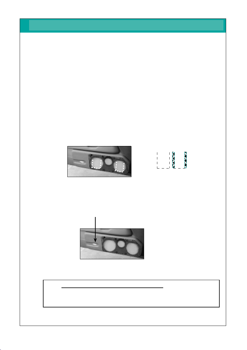
Ausschnitt für Originalleuchte der Türverkleidung
Abb.: Ausschnitt Türverkleidung mit Lautsprecheraussschnitten u. Bohrungen
4. Bearbeitung der Türverkleidung / Montage der Türpaneele
46129 - Golf IV “4türig”- 9 - © JEHNERT SOUND DESIGN
46129 - Golf IV “4türig”- 6 - © JEHNERT SOUND DESIGN
�
Originalleuchte wird im Türpaneel montiert
Schrauben 8 + 9
= bereits im Türpaneel montiert
✃✃
fig.: door lining - speaker cut-outs and drill holes
1. use the precisely aligned panel as template in order to mark fastening points 1- 9:
2. mark the 9 fixing points on the door build with a thin awl
3. draw the speakers’cut-outs onto the door-lining.
4. take away the door build and mark the fixing points.
5. cut out the speakers’outlines acc. to fig.: the original tray has not to be removed
6. use a 6mm drill for the screws according to the marks set before
7. Screw in the M4-screws supplied with. Affix the door build to the door-lining.
Screw all 9 x M4-screws only hand-tight .
Secure all screws with the washers and nuts.
8. check again for precise fitting and tighten screws.
All cutting edges of the panel must fit to the door lining snugly
all around without gap
Do not use !!!
5. Handling of door lining / installation of the door panel
75129 - Golf IV “2-doors”- 7 - © JEHNERT SOUND DESIGN 75129 - Golf IV “2-doors”- 8 - © JEHNERT SOUND DESIGN
cut-out for
subwoofer cut-out for
subwoofer
cut-out for
subwoofer-
enlarged
cut-out for
subwoofer
cut-out for
midrange
4 =
M 4 x 30
3 =
M 4 x 40
2 =
M 4 x 60
1 =
M 4 x 30
9 =
M 4 x 40
8 =
M 4 x 30
7 =
M 4 x 30
6 =
M 4 x 30
10 = Spax 5,0 x 100
No rough drilling -
direct drilling if door build
is installed to the
door lining
5 =
M 4 x 40
11 = Spax 5,0 x 100
No rough drilling -
direct drilling if door build
is installed to the
door lining
☞
6. insulation of the door lining
Important tip:
the use of 4x16mm mid-woofer /side may cause vibrations which lead to
annoying rattle noises in the car door
some helpful tips:
•use our self-adhesive insulation fleece (art.no.: 27000) or a foam material for
the backside of the door lining (see fig. above) or
important: keep the cut-outs for the door-airbags and speakers open
•affix the *backside of the inner door metal with self-adhesive asphalt mats (see fig. * )
•by knocking on the car door, vibrations caused by mechanic parts (e.g. Bowden pull wire etc. )
and wiring harness may be found out. Cover these parts with foamed material, felt or
something like that
•cut off overlapping cable tie (rattle noise)
•adhere felt or foamed material under the original wiring harness
!
Important:
No insulation material behind
- loudspeaker
- door latch lever
- drill a hole for the
installation clip
fig.: backside of the door lining –insulation with our article no.: 27000
moisture protection foil
front side of
inner door metal
*door metal outside
= back side of the
inner door metal
attention –danger !!
No insulation behind the
side-airbags (fig. B)
☞
☞
• marking of xing points 1-7: use a thin awl to set the marks on the door-lining.
• mark the fastening points 8 + 9 premounted in the panel: pressing the panel to the door lining
leaves visible impressions of the screws.
cut-out for entrance light
4. Handling of door lining / Panel installation - Fastening
Remark: The original light will be installed in the door build later on

6. Dämmung der Türverkleidung
Abb.: Beispiel Türverkleidung-Dämmung mit Dämmvlies Art. 27000
Wichtige Empfehlung:
Durch den Einsatz von 2 x 160mm Mid-Woofer / pro Seite
entstehen durch die Schwingungen der Bässe
Vibrationen, die zu Klappergeräuschen in der Fahrzeugtüre
führen können:
Maßnahmen gegen Vibrationsgeräusche:
Türverkleidungsrückseite mit Dämmvlies (Best.Nr. 27000) oder Schaumstoff
bekleben siehe Abb. oben
WICHTIG: Ausschnitte für Lautsprecher u. Türentriegelung unbedingt
freilassen!
und/oder:
(beim Golf IV nicht unbedingt erforderlich):
Türblech innen (Türaußenhaut) mit selbstklebenden Bitumenmatten/
Teermatten bekleben
WICHTIG:
Kein Dämm-Material hinter
- Lautsprecher
- Türentriegelungen
5. Lautsprecherleitungen
Lautsprecherkabel in die Fahrzeugtüren führen:
5.1. Regenschutzfolie vorsichtig entfernen
5.2. Lautsprecherkabel verlegen:
1 x Lautsprecherkabel (1,5 - 4mm 2) vom Verstärker in die
Fahrzeugtüre führen.
Frequenzweichen-Montageort: im Türpaneel - vgl.S.10)
5.3. Regenschutzfolie wieder passgenau anbringen
46129 - Golf IV
“4türig”- 7 - © JEHNERT SOUND DESIGN
46129 - Golf IV “4türig”- 8 - © JEHNERT SOUND DESIGN
☞
☞
!
"
#
!
Loudspeaker wiring diagram
Connect all loudspeakers and crossover circuits:
8. Speaker connection
Insert subwoofer and midrange and connect all loudspeakers
to the crossover circuit (parallel-circuit):
Notice: You should check the polarity of all subwoofers�
before connecting them to the crossover circuit
with a 9 volt battery:
pole of the crossover circuit input to of a 9 Volt battery
pole of the crossover circuit input to of a 9 Volt battery
All subwoofers must move uniformly!
Wrong polarity of a subwoofer can totally
equalize the bass sound!
Packing list ..........................................................................
1. Disassembly of the door lining ..............................................
2. Installation tweeter ..............................................................
3. Paneel alignment / referece points ........................................
4. Handling of door lining / panel installation - fastening ............
5. Lodspeaker cables ................................................................
6. Insulation of the door lining / car door ...................................
7. Installation Crossover + door lining .......................................
8. Speaker connection ..............................................................
Loudspeaker wiring diagram .................................................
9. Installation of the speaker-grill ..............................................
Technical information ...........................................................
Service / fault diagnoses .......................................................
Guarantee ...........................................................................
Packing unit Check list
door panel, covered (right / left) 2
Speaker grill, covered (right / left) 2
tweeter 26 mm 2
tweeter mounting-bowl (with 6Ktn.Screw M4x8,Washer ø12mm) 2
midrange 100 mm Q (each mounted on the panel with 4 Sheet metal-screws) 4
woofer 160 mm (each mounted on the panel with 4 Sheet metal-screws) 16
Crossover (links / rechts) 2
Hardware bag:
$flat head screws, M 4 x 30 10
$flat head screws, M 4 x 40 2
$Spax-screws, 3,0 x 20 2
$Hex nut M 4 18
$Washer Ø 20mm for metric screws 18
$Washer Ø 20mm as s pacer for Velcro fastener 4
$Velcro strip à 2,5 cm (reserve) 4
Preassembled hardware:
%Velcro fastener plus strips 10
%Sheet metal screws, black 3,9 x 13 (for woofer) 16
%Sheet metal screws, black 3,5 x 13 (8x midr.+8x velcro) 16
%flat head screws, M 4 x 30 4
%flat head screws, M 4 x 40 2
The product was carefully packed and checked for its completeness. If you find anything missing, damaged or
defective, please notice our guarantee services on the back of these assembly instructions.
6. insulation of the door lining
!
Important:
No insulation material behind
- loudspeaker
- door latch lever
- (fig. A): drill a hole for the
installation clip
fig. Driver-side
fig. Co-driver - side
9.1. Precisely align and carefully press grill into the Velcro fasteners.
The Velcro fastener makes a crackling sound
when it is closed correctly.
Removing the grills:
The Velcro fasteners stick together very strongly!
The grills can be removed anytime by carefully lifting them off.
Please, avoid any way of forceful yanking at the grills.
It could break!
9.3.
7. Installation Crossover circuit / doorlining
Packing list 45124/46124
3.1. Place the door lining on a plane surface
3.2. Dismount the loudspeakers attached to the panel for transport protection.
Retain the screws for later assembly.
3.3. Place the panel without loudspeakers and grill on the door lining
and align it:
1. use the fastening angle on the backside of the panel and
the precisely aligned panel as template in order to mark fastening points 1- 9:
•mark the fastening points 1-3 _ premounted in the panel:
pressing the panel to the door lining leaves visible impressions of the screws.
•marking of fixing points 5-9:
use a thin awl to set the marks on the door-lining.
2. draw the speakers’ cut-outs onto the door-lining.
3. remove the panel again. cut out holes for loudspeakers along the marking (see fig.)
with a compass saw.
4. use a 6mm drill for the screws according to the marks set before.
5. Screw in the M4-screws supplied with. Affix the door build to the door-lining.
Screw all 9 x M4-screws only hand-tight .
Secure all screws with the washers and nuts.
6. check again for precise fitting and tighten screws.
7. fixing point 10 - »metal screw 3,0 x 20«:
Use a self-cutting metal screw to level out the doorlining and the other
edges of the panel: Screw horrizontally from the buttom to meet the depht
over the top of the midrange through the doorlining.
2.1. pull off the original tweeter out of the catch in the tweeter triangle and disconnect it.
2.2. Enlarge the original tweeter-cutout to the mounting messurement of the
“JEHNERT-tweeter-bowl” with a plaingrinder.
2.3. connect tweeter with loudspeaker cabel (1,5 - 4mm 2) and lead the cable to
the crossover in the car door (see page 10)
2.4. install the “JEHNERT-tweeter-bowl and the tweeter and affix it with a 6Ktn. screw M4x8
or hot melt adhesive or Silicon.
2.5. insert the tweeter-triangle again.
All cutting edges of the panel must fit to the door lining snugly
all around without gap
7.1. Installation Crossover
7.1.1. precable crossovers - see fig. page 11.
7.1.2. affix the crossover with screws directly on the Aluminium-inner door metal–
- without housing - covered with foamed material *- (see fig).
Check precise fit.
* Important: protect the sheet bar against humidity and observe that the
sheet bar does not touch any metal parts – danger of short circuit!
7.2. Installation doorlining onto the car dor
Check up length of the screws and bolts:
7.2.1. in order to prevent damages of mechanic parts of the car doors, please check
once again the length of all bolts and screws on the back side of the door
lining! No touch with any mechanic parts of the car doors !
(please shorten if necessary).
7.2.2. put the door-lining into the upper sealing of the car door
7.2.3. fit it in contrary order of succession as described on page no. 3
1.1. doorlining - driverside :
1.1.1. pull off the faceplate (A) from the innerside of the door handle and remove it.
1.1.2. afterwards unclip the complete door handle with switch-unit from the buttom to
the top. Disconnect the cable plugs. Remove the 3 crosshead screw (C)
underneath.
1.1.3. Remove all 3 Torx-Screws (D1-3) at the lower edge of the door lining and the Torx-
(D4) at the innerside of the doorlining.
1.1.4. lift the door panel out of the sealing above and simultaneously move it
horizontally and forward away from the inner door metal
1.1.5. unplug the connecting-cable of the switch-unit and original loadspeaker
1.1.6. remove the original speaker and the Bowden pull wire
2.2. doorlining - Co-drivers side:
2.2.1. Unclip the door handle faceplate (A1) from the buttom and remove
the 2crosshead screw (F1+2)
2.2.2. Remove all 4 Torx-Screws (D1-4) at the lower edge of the door lining and the Torx-
Screw (E) at the innerside of the doorlining.
2.2.3. carefully squeeze the door panel away from the plastic clips at the lower
and lateral edges of the door lining and move it horizontally and forward away
from the inner door metal.
fig.: Position crossover
Installation crossover
on the Aluminium-inner door metal
(- not on the doorlining!)
8. Lautsprecheranschluss
Tief- und Mitteltöner einsetzen und alle Lautsprecher mit der
Frequenzweiche verkabeln (Paralell-Schaltung):
Hinweis: Bevor alle Tieftöner an die Frequenzweiche angeschlossen werden,�
sollte die Polarität aller Tieftöner an einer 9 Volt-Batterie
überprüft werden:
Pol des FW-Eingang an von 9 V Batterie
Pol des FW-Eingang an von 9 V Batterie
Alle Tieftöner müssen bei dieser Überprüfung gleichmäßig ausschwingen!
Ein verpolter Tieftöner kann die gesamte Basswiedergabe
aufheben!
G u a r a n t e e
9.2. Our Tip:
If the panel cannot be pressed on completely at some points. . .
Cause: the special form at these points and the resulting differences in
material cross section of the grill.
Solution: the distance can be levelled out with spacers 3 under the
Velcro disc.
(Spacers included with the screw kit)
fig.: backside of a door lining – insulation with our article no.: 27000
page
1.1. Fensterscheibe komplett herunterlassen.
1.2. Türgriff-Blende (A1) mit einem Keil von unten aus der Verasterung herausdrücken.
Die darunterliegende 2 Kreutzkopf-Schrauben (F1+2) entfernen.
1.3. Alle 3 Torx-Schrauben (D1- 3) an der Türverkleidungsunterkante und
an der Türverkleidungsinnenseite (E) herausdrehen.
1.4. Türverkleidung an den unteren und seitlichen Türverkleidungsrändern vorsichtig
(Bruchgefahr!) von den Plastikklipsen abdrücken.
1.5. Türverkleidung oben an der Abdichtleitste aus den Klammern herausheben und gleich-
zeitig vom Türinnenblech nach oben wegziehen.
1.6. Türentriegelungsbowdenzug aushängen und Stromkabel zur Einstiegsleuchte und
Lautsprecheranschluss abstecken.
4. Handling of door lining / Panel installation - Fastening
2
3
4
5
6
7
8
9
10
11
12
13
14
15
attention – danger !!
No insulation behind the
side-airbags (fig. B)
45124/46124 - VW Passat - 14 - © JEHNERT SOUND DESIGN
45124/46124 - VW Passat - 13 - © JEHNERT SOUND DESIGN
2004/by.AJ/FH - 15 -
Installation instructions
part-no. 45124 /
46124
Jehnert Sound Design
development and
production of
Car-Audio-Systems
Heinrich-Hertz-Str. 11
70794 Filderstadt
Tel.: 0049-711-77 97 87- 87
Fax: 0049-711-77 78 921
e-mail: sounddesign@jehnert.de
www.jehnert.com
45124/46124 - VW Passat - 7 - © JEHNERT SOUND DESIGN 45124/46124 - VW Passat - 8 - © JEHNERT SOUND DESIGN
Ausschnitt
Tieftöner
Ausschnitt
Mittel töner
45124/46124 - VW Passat - 3 - © JEHNERT SOUND DESIGN
45124/46124 - VW Passat - 9 - © JEHNERT SOUND DESIGN
45124/46124 - VW Passat - 11 - © JEHNERT SOUND DESIGN 45124/46124 - VW Passat - 4 - © JEHNERT SOUND DESIGN
45124/46124 - VW Passat - 10 - © JEHNERT SOUND DESIGN 45124/46124 - VW Passat - 12 - © JEHNERT SOUND DESIGN
45124/46124 - VW Passat - 6 - © JEHNERT SOUND DESIGN
45124/46124 - VW Passat - 5- © JEHNERT SOUND DESIGN
3. Panel alignment
45124/46124 - VW Passat - 1 - © JEHNERT SOUND DESIGN
Reference points for fitting:
Only precise alignment of the panel with the door
lining warrants optimal fit.��
1. Reference line 1:
align the outer edge of the panel flush to the edge of the doorlining.
2. Reference line 2:
the lower edge of the panel is parallel to the lower edge of the door lining.
3. Reference line 3:
the upper edge of the panel is parallel to the edge of the doorlinings-inlet.
Circuit diagram of 2-way crossover / 2x subwoofer
45124/46124 - VW Passat - 2 - © JEHNERT SOUND DESIGN
5. Loudspeaker cables
Important tip:
the use of 2x16mm mid-woofer /side may cause vibrations which lead to
annoying rattle noises in the car door
some helpful tips:
•use our self-adhesive insulation fleece (art.no.: 27000) or a foam material for
the backside of the door lining (see fig. above) or
•stabilize the backside of the door lining by means of a special material
(Glass Fibre Filler or stiffening material)
important: keep the cut-outs for the door-airbags and speakers open
2. Tweeter Installation - Original tweeter-triangle
1 . Disassembly of the door lining
1 =M 4 x 25
2
= M 4 x 50
!
!
!
!
!
A1
F1
F2
!
!
!
!
!
!
!
Lead 1 speaker cable (1,5 - 4mm 2) from amplifier into the door.
(Crossover: car door - see page 10)
!
10= screw in metal-Screw 3,0x20
horizontally (!)
9. Installation of the speaker’s grill :
T e c h n i c a l i n f o r m a t i o n
Equipment: electric window control
Model / year: 4-doors
insulation: see page 8
Note about setting: To obtain optimal stereoscopic sound, all settings
on the radio (bass, treble, loudness etc) should be
set to zero or neutral.
Recommended
amplifier power : from 2x 100 - 200 Watt sinus / 2 Ohm
Metal cutwork: not necessary
Cut-outs for loudspeaker/ 2 x 144mm (max.outer dimensions woofer 165 mm)
each side (max.installaion depth woofer 70 mm)
Euro-Norm standard basket ø 165 / 6” made to fit
1 x 92mm (max.outer dimensions midrange 100 mm)
(max.installaion depth midrange 60 mm)
Sound-System: 3-ways
2 x 160 mm woofer / side
1 x 100 mm midrange / side
1 x 26 mm tweeter / side
car-customized crossover network
max.continuous Watt/RMS: 2 x 160/300Watt
car specific frequency range: 42-22.000 Hz
Total impedance: 2 Ohm
We reserve the right to make technical changes, as well as development.
C o n t e n t s
Particularly important notes contain the following remarks:
Please follow the installation instructions
“step by step”
and check the package contents
We grant a manufacturers guarantee of 2 years starting from the date of purchase
of the door panels or sound system from the dealer.
Within this guarantee period to our choice we either repair or replace free of
charge all defects due to material or workmanship.
Exempt from this guarantee are damages due to improper use, wear and tear or
damages which have to be led back on wear or interventions by third parties.
The guarantee does not cover subsequent damages or such defects that only
insignificantly impair the value or the usability of the panels/sound system.
The guarantee does not cover damages due to external influences.
Panels with additional or wrong assembly drill holes cannot be returned.
These are damages to the panel which cannot be repaired again.
Technical questions Hotline: 0049-711-77 97 87-87
Mirko Schwarz
Development
It is our pleasure to help you!
Marc Sitter
Service
The following notes serve to help troubleshoot and eliminate faults or malfunctions
on your own. If the following measures are not effective, please call us.
What can it be if ... possible cause/ solution
..it doesn’t sound right. wrong polarity on the subwoofers ( page 10)
crosover circuit attached wrong ( page 11)
Doorlining
not cut out ( page 6)
amplifier doesn’t have enough power( page 13)
amplifier connection
...it doesn’t fit correctly. door panel customization ( page 5)
installation of the panels on the door lining (page 6)
.....grills do not hold. observe notes on page 12!
vibrations insulation, see notes on page 8
Self-help and fault diagnosis
!
"
""
"
Final inspection after panel installation:
please check all functions of the operating elements such
as seat adjustment, opening of the glove box,
window winder etc.
reference line 2:
the lower edge of the
panel is parallel to the
lower edge of the door
lining
reference line 1:
outer edge of panel
and doorlining are flush
referece line 3:
upper edge of panel is
parallel to the lower
edge of the doorlinings-
inlet
doorlining:
enlarge the original
cut-ot

6. Dämmung der Türverkleidung
Abb.: Beispiel Türverkleidung-Dämmung mit Dämmvlies Art. 27000
Wichtige Empfehlung:
Durch den Einsatz von 2 x 160mm Mid-Woofer / pro Seite
entstehen durch die Schwingungen der Bässe
Vibrationen, die zu Klappergeräuschen in der Fahrzeugtüre
führen können:
Maßnahmen gegen Vibrationsgeräusche:
Türverkleidungsrückseite mit Dämmvlies (Best.Nr. 27000) oder Schaumstoff
bekleben siehe Abb. oben
WICHTIG: Ausschnitte für Lautsprecher u. Türentriegelung unbedingt
freilassen!
und/oder:
(beim Golf IV nicht unbedingt erforderlich):
Türblech innen (Türaußenhaut) mit selbstklebenden Bitumenmatten/
Teermatten bekleben
WICHTIG:
Kein Dämm-Material hinter
- Lautsprecher
- Türentriegelungen
5. Lautsprecherleitungen
Lautsprecherkabel in die Fahrzeugtüren führen:
5.1. Regenschutzfolie vorsichtig entfernen
5.2. Lautsprecherkabel verlegen:
1 x Lautsprecherkabel (1,5 - 4mm 2) vom Verstärker in die
Fahrzeugtüre führen.
Frequenzweichen-Montageort: im Türpaneel - vgl.S.10)
5.3. Regenschutzfolie wieder passgenau anbringen
46129 - Golf IV “4türig”- 7 - © JEHNERT SOUND DESIGN
46129 - Golf IV “4türig”- 8 - © JEHNERT SOUND DESIGN
☞
☞
fig.: door lining - speaker cut-outs and drill holes
1. use the precisely aligned panel as template in order to mark fastening points 1- 9:
2. mark the 9 fixing points on the door build with a thin awl
3. draw the speakers’cut-outs onto the door-lining.
4. take away the door build and mark the fixing points.
5. cut out the speakers’outlines acc. to fig.: the original tray has not to be removed
6. use a 6mm drill for the screws according to the marks set before
7. Screw in the M4-screws supplied with. Affix the door build to the door-lining.
Screw all 9 x M4-screws only hand-tight .
Secure all screws with the washers and nuts.
8. check again for precise fitting and tighten screws.
All cutting edges of the panel must fit to the door lining snugly
all around without gap
Do not use !!!
5. Handling of door lining / installation of the door panel
75129 - Golf IV “2-doors”- 7 - © JEHNERT SOUND DESIGN 75129 - Golf IV “2-doors”- 8 - © JEHNERT SOUND DESIGN
cut-out for
subwoofer cut-out for
subwoofer
cut-out for
subwoofer-
enlarged
cut-out for
subwoofer
cut-out for
midrange
4 =
M 4 x 30
3 =
M 4 x 40
2 =
M 4 x 60
1 =
M 4 x 30
9 =
M 4 x 40
8 =
M 4 x 30
7 =
M 4 x 30
6 =
M 4 x 30
10 = Spax 5,0 x 100
No rough drilling -
direct drilling if door build
is installed to the
door lining
5 =
M 4 x 40
11 = Spax 5,0 x 100
No rough drilling -
direct drilling if door build
is installed to the
door lining
☞
6. insulation of the door lining
Important tip:
the use of 4x16mm mid-woofer /side may cause vibrations which lead to
annoying rattle noises in the car door
some helpful tips:
•use our self-adhesive insulation fleece (art.no.: 27000) or a foam material for
the backside of the door lining (see fig. above) or
important: keep the cut-outs for the door-airbags and speakers open
•affix the *backside of the inner door metal with self-adhesive asphalt mats (see fig. * )
•by knocking on the car door, vibrations caused by mechanic parts (e.g. Bowden pull wire etc. )
and wiring harness may be found out. Cover these parts with foamed material, felt or
something like that
•cut off overlapping cable tie (rattle noise)
•adhere felt or foamed material under the original wiring harness
!
Important:
No insulation material behind
- loudspeaker
- door latch lever
- drill a hole for the
installation clip
fig.: backside of the door lining –insulation with our article no.: 27000
moisture protection foil
front side of
inner door metal
*door metal outside
= back side of the
inner door metal
attention –danger !!
No insulation behind the
side-airbags (fig. B)
☞
☞
gure example
1 =
M 4 x 30
8 =
M 4 x 40
9 =
M 4 x 40 5 =
M 4 x 30
2 =
M 4 x 60
3 =
M 4 x 50
4 =
M 4 x 50
6 =
M 4 x 30
7 =
M 4 x 40
Ausschnitt
Tieftöner
“vergrößern”
Ausschnitt
Mitteltöner
Ausschnitt
Tieftöner
7. Montage der Türverkleidung auf die Fahrzeugtüren
7.1. Zum Schutz gegen Nässe und Beschädigung der Lautsprecher durch
Feuchtigkeit:
Regenschutzfolie (handelsübliche Plastikfolie / Sack) in Größe
der Aussparung hinter dem werkseitigen Lautsprecher, auf dem Türblech
z.B. mit Sprühkleber / Klebeband nachträglich anbringen.
7.2. Türverkleidung oben in die Türschachtleiste einhängen
7.3. In umgekehrter Reihenfolge wie auf Seite 3 beschrieben wieder befestigen.
7.4. Zur Steigerung des Klangvolumens die nachgerüstete Regenschutzfolie
hinter den Lautsprecheröffnungen entweder nur unten oder
u-förmig einschneiden.
Bei u-förmigem Ausschnitt: Seitliche Schnittkanten zur Vermeidung von
Vibrationsgeräuschen der Folie stabilisieren ( z.B. mit Packband).
7.5. Originalleuchte in die vorgesehene Öffnung im Türpaneel
einklipsen und anschließen.
1. Zur Markierung der Befestigungspunkte auf der Türverkleidung das
passgenau justierte Paneel als Schablone verwenden :
Befestigungspunkte 1 - 7: mit einem dünnen Vorstecher markieren
Befestigungspunkte 8 +9: Schraubenabdrücke durch Aufdrücken sichtbar machen.
3. Die Lautsprecher-Öffnungen auf der Türverkleidung anzeichnen.
4. Paneel wieder abnehmen und die Befestigungs-Markierungen anzeichnen.
5. Die Lautsprecher-Öffnungen ausschneiden (siehe Abb.):
Die Original-Kartentasche muss nicht enfernt werden.
6. Für die einzusetzenden Schrauben die Bohrungen gemäß Markierung
mit einem 6mm-Bohrer vornehmen.
7. Türpaneel mit der Türverkleidung durch handfestes Anziehen der
M4-Schrauben (vgl. Abb.unten) fixieren.
Alle Schrauben mit den Unterlagscheiben und Muttern sichern.
8. Nochmals Passgenauigkeit überprüfen und Schrauben festziehen.
Alle Schnittkanten des Paneels müssen umlaufend ohne Spalt
auf der Türverkleidung anliegen.
Hinweis: Die Original-Leuchte wird später im Türpaneel montiert.
�Endkontrolle nach Türpaneel-Montage:
Alle Funktionen der Bedienelemente wie Sitzverstellung,
Handschuhfachöffnung, Fensterheber etc. überprüfen.
Ausschnitt für Originalleuchte der Türverkleidung
Abb.: Ausschnitt Türverkleidung mit Lautsprecheraussschnitten u. Bohrungen
4. Bearbeitung der Türverkleidung / Montage der Türpaneele
46129 - Golf IV “4türig”- 9 - © JEHNERT SOUND DESIGN
46129 - Golf IV “4türig”- 6 - © JEHNERT SOUND DESIGN
�
Originalleuchte wird im Türpaneel montiert
Schrauben 8 + 9
= bereits im Türpaneel montiert
✃✃
7.1. Protection against moisture and damage of the speakers by humidity:
Put a protection foil (standard foil or bag) in the size of the cut-outs behind the original
speaker - use some adhesive spray or adhesive tape.
7.2. Put the door-lining into the upper sealing of the car door.
7.3. Fit it in contrary order of succession as described on page no. 3.
7.4. Cut out the moisture protection foil (u-form) and stabilize the lateral cutting edges in
order to avoid vibration noise ( e.g. use a packing tape).
7.5. Click the original light into the opening provided in the door build and connect it.
7. Installation of the door-lining onto the the car doors
packing tape
!
"
#
!
Loudspeaker wiring d iagram
Connect al l loudspeakers and crossover circuits:
8. Speaker connection
Insert subwoo fer and mi drang e and conn ect all loudspeakers
to t he crossover cir cuit (parall el-circuit):
Notice: You should check the polarity o f all sub woofers�
before connecting them to the crossover circu it
with a 9 volt battery:
pole of the cr ossover circuit input to of a 9 Volt batter y
pole of the cross over circuit input to of a 9 Volt batter y
All sub woofers mu st mo ve uniformly!
Wrong polarity of a subw oofer can totally
equaliz e the bass so und!
Packing list ..........................................................................
1. Disassembly of the door lining ..............................................
2. Installation tweeter ..............................................................
3. Paneel alignment / referece points ........................................
4. Handling of door lining / panel installation - fastening ............
5. Lodspeaker cables ................................................................
6. Insulation of the door lining / car door ...................................
7. Installation Crossover + door lining .......................................
8. Speaker connection ..............................................................
Loudspeaker wiring diagram .................................................
9. Installation of the speaker-grill ..............................................
Technical information ...........................................................
Service / fault diagnoses .......................................................
Guarantee ...........................................................................
Packing unit Check list
door panel, covered (ri gh t / lef t) 2
Speaker g rill, c overed (ri ght / lef t) 2
tweeter 26 mm 2
tweeter mounting-bowl (wit h 6 Kt n.S crew M4 x8,Wa she r ø 12mm ) 2
midrange 100 mm Q (each moun ted on the panel with 4 Sheet me tal- screws) 4
woofer 160 mm (each moun ted on the panel with 4 Sheet me tal-sc rews) 16
Crossover (links / rechts) 2
Hardware bag:
$flat head screws, M 4 x 30 10
$flat head screws, M 4 x 40 2
$Spax-screws, 3,0 x 20 2
$Hex nut M 4 18
$Washer Ø 20mm for me tric screws 18
$Washer Ø 20mm as s pa cer for Velc ro fa ste ner 4
$Velcro strip à 2,5 cm (res erve) 4
Preassembled hardware:
%Velcro fastener plus strips 10
%Sheet metal screws, black 3,9 x 13 (for woo fer) 16
%Sheet metal screws, black 3,5 x 13 (8x midr.+8x velcro) 16
%flat head screws, M 4 x 30 4
%flat head screws, M 4 x 40 2
The product was carefully packed and checked for its completeness. If you find anything missing, damaged or
defective, please notice our guarantee services on the back of these assembly instructions.
6. insulation of the door lining
Important:
No insulation material behind
- loudspeaker
- door latch lever
- (fig. A): drill a hole for the
installation clip
fig. D river-side
fig. C o-driver - side
9.1. Precise ly align and ca refull y press gri ll into the Velcro fasteners.
The Velcro fastener makes a crackling sou nd
when it is clo sed correctly.
Removing the grills:
The Velcro fasteners stick together very strongly!
The grills can be removed anytime by carefully lifting them off.
Please, avoid any way of forceful yanking at the grills.
It could break!
9.3.
7. Installation Crossover circuit / doorlining
Packing list 45124/46124
3.1. Place the door lining on a pl ane surface
3.2. Dismount the louds peakers at tached to the panel for transport protecti on.
Retain t he screws f or later assembly.
3.3. Place the pan el without loudspeakers and gr ill on the door lining
and align i t:
1. use the fastening angle on the backside of the panel and
the precisely aligned panel as template in order to mark fastening points 1- 9:
•mark the fastening points 1-3 _ premounted in the panel:
pressing the panel to the door lining leaves visible impressions of the screws.
•marking of fixing points 5-9:
use a thin awl to set the marks on the door-lining.
2. draw the speakers’ cut-outs onto the door-lining.
3. remove the panel again. cut out holes for loudspeakers along the marking (see fig.)
with a compass saw.
4. use a 6mm drill for the screws according to the marks set before.
5. Screw in the M4-screws supplied with. Affix the door build to the door-lining.
Screw all 9 x M4-screws only hand-tight .
Secure all screws with the washers and nuts.
6. check again for precise fitting and tighten screws.
7. fixing point 10 - »metal screw 3,0 x 20«:
Use a self-cutting metal screw to level out the doorlining and the other
edges of the panel: Screw horrizontally from the buttom to meet the depht
over the top of the midrange through the doorlining.
2.1. pu ll off the origin al twe eter out of the catc h in the tweeter trian gle and disconnect it.
2.2. En large the original tweeter-cutout to th e mounting me ssurement of the
“JE HNERT-tweeter-bowl” with a plaingrinder.
2.3. connect t weeter with loudspeaker cabel (1,5 - 4m m 2) and lead the ca ble to
the cross over in the car door (see pa ge 10)
2.4. insta ll the “JE HNERT-tweeter-bowl an d the tweeter and affix it with a 6Ktn . screw M4 x8
or hot melt ad hesive or Silico n.
2.5. inse rt t he tweeter-trian gle aga in.
All cutting edges of the panel must fit to the door lining snugly
all around without gap
7.1. Installation Crossover
7.1.1. precable crossovers - see fig. page 11.
7.1.2. affix the crossover with screws directly on the Aluminium-inner door metal–
- without housing - covered with foamed material *- (see fig).
Check precise fit.
* Important: protect the sheet bar against humidity and observe that the
sheet bar does not touch any metal parts – danger of short circuit!
7.2. Installation doorlining onto the car dor
Check up length of the screws and bolts:
7.2.1. in order to prevent damages of mechanic parts of the car doors, please check
once again the length of all bolts and screws on the back side of the door
lining! No touch with any mechanic parts of the car doors !
(please shorten if necessary).
7.2.2. put the door-lining into the upper sealing of the car door
7.2.3. fit it in contrary order of succession as described on page no. 3
1.1. doorlining - driverside :
1.1.1. pull off the faceplate (A) from the innerside of the door ha ndle a nd remove it.
1.1.2. after wards unclip the complete door h andle with switc h-unit from the buttom to
t he top. Disconnect the cable plugs. Remo ve th e 3 crosshead sc rew (C)
u nderneath.
1.1.3. Remo ve all 3 Torx-S crews (D1 -3) at th e lower edge of the door lin ing and the Torx-
(D4 ) at th e inn erside of the doorlin ing.
1.1.4. lift the door panel out of the sealing above and simultaneously move it
horizontally and forward away from the inner door metal
1.1.5. u nplug the connecting-cable of the switc h-unit and origina l loadspeaker
1.1.6. re move the origin al speaker a nd the Bowden pull wire
2.2. doorlining - Co- drivers side:
2.2.1. Unclip the door handle faceplate (A1 ) from the buttom and remove
the 2cross head scre w (F1+2)
2.2.2. Rem ove all 4 Torx-S crews (D1 -4) at th e lower edge of the door lin ing and the Torx-
Sc rew (E) at th e inn erside of the doorlin ing.
2.2.3. carefully squeeze the door panel away from the plastic clips at the lower
and lateral edges of the door lining and move it horizontally and forward away
from the inner door metal.
fig.: Position crossover
Installation crossover
on the Aluminium-inner door metal
(- not on the doorlining!)
8. Lautsprecheranschluss
Tief- und Mitteltöner einsetzen und alle Lautsprecher mit der
Frequenzweiche verkabeln (Paralell-Schaltung):
Hinweis: Bevor alle Tieftöner an die Frequenzweiche angeschlossen werden,�
sollte die Polarität aller Tieftöner an einer 9 Volt-Batterie
überprüft werden:
Pol des FW-Eingang an von 9 V Batterie
Pol des FW-Eingang an von 9 V Batterie
Alle Tieftöner müssen bei dieser Überprüfung gleichmäßig ausschwingen!
Ein verpolter Tieftöner kann die gesamte Basswiedergabe
aufheben!
8. Lautsprecheranschluss
Tief- und Mitteltöner einsetzen und alle Lautsprecher mit der
Frequenzweiche verkabeln (Paralell-Schaltung):
Hinweis: Bevor alle Tieftöner an die Frequenzweiche angeschlossen werden,�
sollte die Polarität aller Tieftöner an einer 9 Volt-Batterie
überprüft werden:
Pol des FW-Eingang an von 9 V Batterie
Pol des FW-Eingang an von 9 V Batterie
Alle Tieftöner müssen bei dieser Überprüfung gleichmäßig ausschwingen!
Ein verpolter Tieftöner kann die gesamte Basswiedergabe
aufheben!
G u a r a n t e e
9.2. Our Tip:
If th e panel can not be pressed on completely at some points. . .
Cause: the special form at these p oints an d the re sultin g differences in
material cross sec tion of the grill.
Solution: the dista nce can be levelled out with sp acers 3 under the
Velcro d isc.
(Spacers include d with the screw kit)
fig.: backside of a door lining – insulation with our article no.: 27000
page
1.1. Fensterscheibe komplett he runterlassen.
1.2. Türgriff-Blen de (A1) m it einem Keil v on unten aus der Verasterung herausdrücken.
Die darunterlieg ende 2 Kre utzkopf-Schrauben (F1+2) entfern en.
1.3. Alle 3 Torx-Schrauben (D1- 3) an der Türverkleid ungsunterkante und
an der Türverkleidungsinnenseite (E) herausdrehen.
1.4. Türverkleid ung an den unteren und se itlichen Türverkleidungsrändern vorsichtig
(Bruc hgefahr!) von den Plastikklipsen abdrücken.
1.5. Türverkleid ung oben an der Abdichtleitste au s den Klammern herausheben und gleic h-
zeitig v om Türinnenblech nach oben wegziehen.
1.6. Türentrie gelungsbowdenzug aushängen und Stromkabel zur Einstieg sleuchte und
Lautsprecheranschluss abstecken.
4. Handling of door lining / Panel installation - Fastening
2
3
4
5
6
7
8
9
10
11
12
13
14
15
attention – danger !!
No insulation behind the
side-airbags (fig. B)
45124/46124 - VW Passat - 14 - © JEHNERT SOUND DESIGN
45124/46124 - VW Passat - 13 - © JEHNERT SOUND DESIGN
2004/by.AJ/FH - 15 -
Installation instructions
part-no. 45124 /
46124
Jehnert Sound Design
development and
production of
Car-Audio-Systems
Heinrich-Hertz-Str. 11
70794 Filderstadt
Tel.: 0049-711-77 97 87- 87
Fax: 0049-711-77 78 921
e-mail: sounddesign@jehnert.de
www.jehnert.com
45124/46124 - VW Passat - 7 - © JEHNERT SOUND DESIGN 45124/46124 - VW Passat - 8 - © JEHNERT SOUND DESIGN
Ausschnitt
Tieftön er
Ausschnitt
Mitteltöner
45124/46124 - VW Passat - 3 - © JEHNERT SOUND DESIGN
45124/46124 - VW Passat - 9 - © JEHNERT SOUND DESIGN
45124/46124 - VW Passat - 11 - © JEHNERT SOUND DESIGN 45124/46124 - VW Passat - 4 - © JEHNERT SOUND DESIGN
45124/46124 - VW Passat - 10 - © JEHNERT SOUND DESIGN 45124/46124 - VW Passat - 12 - © JEHNERT SOUND DESIGN
45124/46124 - VW Passat - 6 - © JEHNERT SOUND DESIGN
45124/46124 - VW Passat - 5- © JEHNERT SOUND DESIGN
3. Panel alignment
45124/46124 - VW Passat - 1 - © JEHNERT SOUND DESIGN
Reference points for fitting:
Only precise alignment of the panel with the door
lining w arrants op timal fit.��
1. Reference li ne 1:
align the outer edge of the panel flush to the edg e of the doorlining.
2. Reference li ne 2:
the lower edge of the panel is parallel to the lower edge of the door lining.
3. Reference li ne 3:
the upper edge of the panel is parall el to the edg e of the doorl inings -inlet.
Circuit diagram of 2-way crossover / 2x subwoofer
45124/46124 - VW Passat - 2 - © JEHNERT SOUND DESIGN
5. Loudspeaker cables
Important tip:
the use of 2x16mm mid-woofer /side may cause vibrations which lead to
annoying rattle noises in the car door
some helpful tips:
• use our self-adhesive insulation fleece (art.no.: 27000) or a foam material for
the backside of the door lining (see fig. above) or
• stabilize the backside of the door lining by means of a special material
(Glass Fibre Filler or stiffening material)
important: keep the cut-outs for the door-airbags and speakers open
2. Tweeter Installation - Original tweeter-triangle
1 . Disassembly of the door lining
1 =M 4 x 25
2
= M 4 x 50
!
!
!
!
!
A1
F1
F2
!
!
!
!
!
!
!
Lead 1 speaker cable (1, 5 - 4mm 2) from ampli fier into the door.
(Crossover: car door - see page 10)
!
10= screw in metal-Screw 3,0x20
horizontally (!)
9. Installation of the s peaker’s grill :
T e c h n i c a l i n f o r m a t i o n
Equipment: electric window control
Model / year: 4-doors
insulation: see page 8
Note about setting: To obtain optimal stereoscopic sound, all settings
on the radio (bass, treble, loudness etc) should be
set to zero or neutral.
Recommended
amplifier power : from 2x 100 - 200 Watt sinus / 2 Ohm
Metal cutwork: not necessary
Cut-outs for loudspeaker/ 2 x 144mm (max.outer dimensions woofer 165 mm)
each side (max.installaion depth woofer 70 mm)
Euro-Norm standard basket ø 165 / 6” made to fit
1 x 92mm (max.outer dimensions midrange 100 mm)
(max.installaion depth midrange 60 mm)
Sound-System: 3-ways
2 x 160 mm woofer / side
1 x 100 mm midrange / side
1 x 26 mm tweeter / side
car-customized crossover network
max.continuous Watt/RMS: 2 x 160/300Watt
car specific frequency range: 42-22.000 Hz
Total impedance: 2 Ohm
We reserve the right to make technical changes, as well as development.
C o n t e n t s
Particularly important notes contain the following remarks:
Please follow the installation instructions
“step by step”
and check the package contents
We grant a manufacturers gua rantee of 2 years start ing fr om the date of purcha se
of the doo r panels or soun d system f rom the dea ler.
Within this guarantee peri od to our choice we either repair or replace free of
charge all defects due t o materi al or wor kmansh ip.
Exempt from this guarantee ar e damages due t o improper use, wear and t ear or
damages which hav e to be l ed back on wear or interventions by third parties.
The guarantee does not cover subsequent damage s or such defects t hat only
insignif icantly impair the va lue or the usabili ty of the pane ls/sound sy stem.
The guarantee does not cover damages due to external influences.
Panels with additional or wrong assembl y drill holes cann ot be r eturned.
These are damage s to the panel whi ch cannot be r epaired again.
Technical questions Hotline: 0049-711-77 97 87-87
Mirko Schwarz
Development
It is our pleasure to help you!
Marc Sitter
Service
The following notes serve to help troubleshoot and eliminate faults or malfunctions
on your own. If the following measures are not effective, please call us.
What can it be if ... possible cause/ solution
..it doesn’t sound right. wrong polarity on the subwoofers ( page 10)
crosover circuit attached wrong ( page 11)
Doorlining
not cut out ( page 6)
amplifier doesn’t have enough power( page 13)
amplifier connection
...it doesn’t fit correctly. door panel customization ( page 5)
installation of the panels on the door lining (page 6)
.....grills do not hold. observe notes on page 12!
vibrations insulation, see notes on page 8
Self-help and fault diagnosis
!
"
""
"
Final inspection after panel installation:
please check all functions of the operating elements such
as seat adjustment, opening of the glove box,
window winder etc.
re fer e nc e li ne 2:
the lower edge of the
panel is parallel to the
lower edge of the door
lining
re fer e nc e li ne 1:
outer edge of panel
and doorlining are flush
re fer ece l ine 3:
upper edge of panel is
parallel to the lower
edge of the doorlinings-
inlet
doorlining:
enlarge the original
cut-ot
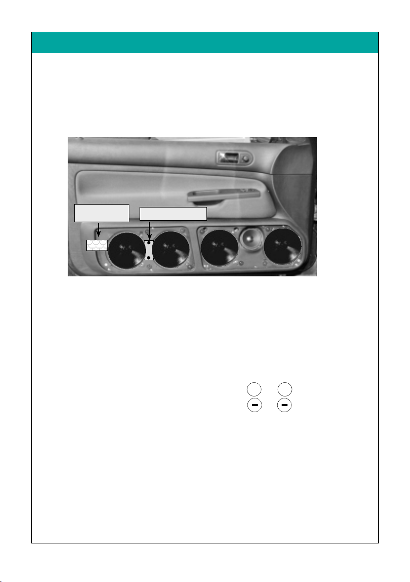
8. Frequenzweichenmontage + Lautsprecheranschluss
8.1. Frequenzweichen vorverkabeln - vgl. Abb. Seite 11.
8.2. Frequenzweiche im Hohlraum zwischen Türpaneel und Türverkleidung
(siehe Abb.) einsetzen und befestigen.
WICHTIG: Platine vor Feuchtigkeit schützen und darauf achten,
dass die Platine nicht an Metallteilen anliegt - Kurzschlussgefahr !
8.3. Tief- und Mitteltöner einsetzen und alle Lautsprecher mit der
Frequenzweiche verkabeln (Paralell-Schaltung):
Hinweis: Bevor alle Tieftöner an die Frequenzweiche angeschlossen werden,
sollte die Polarität aller Tieftöner an einer 9 Volt-Batterie
überprüft werden:
Pol des FW-Eingang an von 9 V Batterie
Pol des FW-Eingang an von 9 V Batterie
Alle Tieftöner müssen bei dieser Überprüfung gleichmäßig ausschwingen!
Ein verpolter Tieftöner kann die gesamte Basswiedergabe
aufheben!
Fixpunktlinie 2
(Linie 2
ralell zu
Fixpunktlinie 4:
Abstand gerade Paneelseiten-
kante zur Designlinie der
Türverkleidung = etwa12mm
Fixpunktlinie 3:
Abstand schräge Paneelseiten-
kante zur Designlinie der
Türverkleidung = etwa 5mm
Fixpunktlinie 1
3.1. Türverkleidung auf eine ebene Fläche legen.
3.2. Die auf dem Paneel zur Transportsicherung befestigten Lautsprecher
demontieren (Schrauben zur späteren Montage aufbewahren).
3.3. Das Paneel ohne Lautsprecher auf die Türverkleidung legen und ausrichten:
Fixpunktlinien zur Anpassung:
Nur die exakte Anpassung des Paneeles auf die Türverkleidung
gewährleistet eine optimale Passgenauigkeit
1. Die Oberkante des Paneels paralell zur Linie (1) der Türverkleidung und
zur Türverkleidungsunterkante (Linie 2) anpassen.
2. Darauf achten, daßdie vordere Seitenkante vom Paneel paralell zur
Designlinie der Türverkleidung läuft (Linie 3+4):
2.1. Abstand zwischen
schräger
Seitenkante des Paneels und Designlinie
der Türverkleidung etwa ca. 5mm (Linie 3)
2.2. Abstand zwischen
geraden
Seitenkante des Paneels und Designlinie
der Türverkleidung etwa 12mm (Linie 4).
46129 - Golf IV “4türig”- 10 - © JEHNERT SOUND DESIGN
46129 - Golf IV “4türig”- 5- © JEHNERT SOUND DESIGN
3.Paneelanpassung
�
�
Hochtöner
Tieftöner
SoundSound
DESIGN
JEHNERT
Mitteltöner
Eingang
3-Wege fahrzeugspezifischeFrequenzweiche
Golf I V
✚ ✚
Nachdem alle Tieftöner an die Frequenzweiche angeschlossen
sind, sollte die Polarität aller Tieftöner an einer 9-Volt-Batterie
überprüft werden (an Weicheneingangskabel auf Endstufenseite).
cover the cut-out of the door
metal with plastic foil
8. Crossover circuit - Speaker connection
8.1. pre-cable crossovers (cables for subwoofer supplied with), see fig. on page 11
8.2. install crossovers without housing onto the door build:
8.2.1. affix front 3-way crossover with 2 sheet metal screws
8.2.2. cover the rear crossover for the subwoofer with foamed
plastic and install it
8.3. Insert subwoofer and midrange and connect all loudspeakers
with the included standart cables for subwoofer to the crossover circuit:
parallel wiring see diagram on page 11.
Notice: You should check the polarity of all subwoofers
before connecting them to the crossover circuit
with a 9 volt battery:
pole of the crossover circuit input to of a 9 Volt battery
pole of the crossover circuit input to of a 9 Volt battery
All subwoofers must move uniformly!
Wrong polarity of a subwoofer can totally
equalize the bass sound!
Oi
Merkm
75129 - Golf IV “2-doors”- 5 - © JEHNERT SOUND DESIGN 75129 - Golf IV “2-doors”- 10 - © JEHNERT SOUND DESIGN
car customized
subwoofer
crossover-circuit
3. metal work / speaker connection
3.1. cut-out of inner door metal
To boost the sound the cut-outs for the speakers have to be enlarged:
the original cut-out of the Golf IV in the car door is very small –
we need a further cut-out of the door metal to boost the sound volume:
3.1.1. cut out the inner door metal as shown on the fig. above –
use a compressed air-compass saw or a tinners’snip
3.1.2. affix with plastic foil in order to avoid humidity
3.2. Loudspeaker cable into the doors:
install cables:
Lead 1 speaker cable (1,5 - 4mm 2) from amplifier into the door.
(mount of crossover circuit: door build –see page 10)
�
Oi
Merkm
Oi
Merkm
Oi
Merkm
car customized
3-ways crossover-circuit
add. insulation of the door lining
see page 8
✚ ✚

!
"
#
!
Loudspeaker wiring diagram
Connect all loudspeakers and crossover circuits:
8. Speaker connection
Insert subwoo fer and mi drang e and conn ect all loudspeakers
to t he crossover cir cuit (parall el-circuit):
Notice: You should check the polarity o f all sub woofers�
before connecting them to the crossover circu it
with a 9 volt battery:
pole of the cr ossover circuit input to of a 9 Volt batter y
pole of the cross over circuit input to of a 9 Volt batter y
All sub woofers must move uniformly!
Wrong polarity of a subwoofer can totally
equaliz e the bass so und!
Loudspeaker wiring diagram
Connect all loudspeakers and crossover circuits:
Packing list ..........................................................................
1. Disassembly of the door lining ..............................................
2. Installation tweeter ..............................................................
3. Paneel alignment / referece points ........................................
4. Handling of door lining / panel installation - fastening ............
5. Lodspeaker cables ................................................................
6. Insulation of the door lining / car door ...................................
7. Installation Crossover + door lining .......................................
8. Speaker connection ..............................................................
Loudspeaker wiring diagram .................................................
9. Installation of the speaker-grill ..............................................
Technical information ...........................................................
Service / fault diagnoses .......................................................
Guarantee ...........................................................................
Packing unit Check list
door panel, covered (ri gh t / lef t) 2
Speaker g rill, c overed (ri ght / lef t) 2
tweeter 26 mm 2
tweeter mounting-bowl (wit h 6 Kt n.S crew M4 x8,Wa she r ø 12mm ) 2
midrange 100 mm Q (each moun ted on the panel with 4 Sheet me tal- screws) 4
woofer 160 mm (each moun ted on the panel with 4 Sheet me tal-sc rews) 16
Crossover (links / rechts) 2
Hardware bag:
$flat head screws, M 4 x 30 10
$flat head screws, M 4 x 40 2
$Spax-screws, 3,0 x 20 2
$Hex nut M 4 18
$Washer Ø 20mm for me tric screws 18
$Washer Ø 20mm as s pa cer for Velc ro fa ste ner 4
$Velcro strip à 2,5 cm (res erve) 4
Preassembled hardware:
%Velcro fastener plus strips 10
%Sheet metal screws, black 3,9 x 13 (for woo fer) 16
%Sheet metal screws, black 3,5 x 13 (8x midr.+8x velcro) 16
%flat head screws, M 4 x 30 4
%flat head screws, M 4 x 40 2
The product was carefully packed and checked for its completeness. If you find anything missing, damaged or
defective, please notice our guarantee services on the back of these assembly instructions.
6. insulation of the door lining
Important:
No insulation material behind
- loudspeaker
- door latch lever
- (fig. A): drill a hole for the
installation clip
fig. Driver-side
fig. Co-driver - side
9.1. Precisely align and carefully press grill into the Velcro fasteners.
The Velcro fastener makes a crackling sound
when it is closed correctly.
Removing the grills:
The Velcro fasteners stick together very strongly!
The grills can be removed anytime by carefully lifting them off.
Please, avoid any way of forceful yanking at the grills.
It could break!
9.3.
7. Installation Crossover circuit / doorlining
Packing list 45124/46124
3.1. Place the door lining on a pl ane surface
3.2. Dismount the louds peakers at tached to the panel for transport protecti on.
Retain t he screws f or later assembly.
3.3. Place the pan el without loudspeakers and gr ill on the door lining
and align i t:
1. use the fastening angle on the backside of the panel and
the precisely aligned panel as template in order to mark fastening points 1- 9:
•mark the fastening points 1-3 _ premounted in the panel:
pressing the panel to the door lining leaves visible impressions of the screws.
•marking of fixing points 5-9:
use a thin awl to set the marks on the door-lining.
2. draw the speakers’ cut-outs onto the door-lining.
3. remove the panel again. cut out holes for loudspeakers along the marking (see fig.)
with a compass saw.
4. use a 6mm drill for the screws according to the marks set before.
5. Screw in the M4-screws supplied with. Affix the door build to the door-lining.
Screw all 9 x M4-screws only hand-tight .
Secure all screws with the washers and nuts.
6. check again for precise fitting and tighten screws.
7. fixing point 10 - »metal screw 3,0 x 20«:
Use a self-cutting metal screw to level out the doorlining and the other
edges of the panel: Screw horrizontally from the buttom to meet the depht
over the top of the midrange through the doorlining.
2.1. pull off the original tweeter out of the catch in the tweeter triangle and disconnect it.
2.2. Enlarge the original tweeter-cutout to the mounting messurement of the
“JEHNERT-tweeter-bowl” with a plaingrinder.
2.3. connect tweeter with loudspeaker cabel (1,5 - 4mm 2) and lead the cable to
the crossover in the car door (see page 10)
2.4. install the “JEHNERT-tweeter-bowl and the tweeter and affix it with a 6Ktn. screw M4x8
or hot melt adhesive or Silicon.
2.5. insert the tweeter-triangle again.
All cutting edges of the panel must fit to the door lining snugly
all around without gap
7.1. Installation Crossover
7.1.1. precable crossovers - see fig. page 11.
7.1.2. affix the crossover with screws directly on the Aluminium-inner door metal–
- without housing - covered with foamed material *- (see fig).
Check precise fit.
* Important: protect the sheet bar against humidity and observe that the
sheet bar does not touch any metal parts – danger of short circuit!
7.2. Installation doorlining onto the car dor
Check up length of the screws and bolts:
7.2.1. in order to prevent damages of mechanic parts of the car doors, please check
once again the length of all bolts and screws on the back side of the door
lining! No touch with any mechanic parts of the car doors !
(please shorten if necessary).
7.2.2. put the door-lining into the upper sealing of the car door
7.2.3. fit it in contrary order of succession as described on page no. 3
1.1. doorlining - driverside :
1.1.1. pull off the faceplate (A) from the innerside of the door handle and remove it.
1.1.2. afterwards unclip the complete door handle with switch-unit from the buttom to
the top. Disconnect the cable plugs. Remove the 3 crosshead screw (C)
underneath.
1.1.3. Remove all 3 Torx-Screws (D1-3) at the lower edge of the door lining and the Torx-
(D4) at the innerside of the doorlining.
1.1.4. lift the door panel out of the sealing above and simultaneously move it
horizontally and forward away from the inner door metal
1.1.5. unplug the connecting-cable of the switch-unit and original loadspeaker
1.1.6. remove the original speaker and the Bowden pull wire
2.2. doorlining - Co-drivers side:
2.2.1. Unclip the door handle faceplate (A1) from the buttom and remove
the 2crosshead screw (F1+2)
2.2.2. Remove all 4 Torx-Screws (D1-4) at the lower edge of the door lining and the Torx-
Screw (E) at the innerside of the doorlining.
2.2.3. carefully squeeze the door panel away from the plastic clips at the lower
and lateral edges of the door lining and move it horizontally and forward away
from the inner door metal.
fig.: Position crossover
Installation crossover
on the Aluminium-inner door metal
(- not on the doorlining!)
8. Lautsprecheranschluss
Tief- und Mitteltöner einsetzen und alle Lautsprecher mit der
Frequenzweiche verkabeln (Paralell-Schaltung):
Hinweis: Bevor alle Tieftöner an die Frequenzweiche angeschlossen werden,�
sollte die Polarität aller Tieftöner an einer 9 Volt-Batterie
überprüft werden:
Pol des FW-Eingang an von 9 V Batterie
Pol des FW-Eingang an von 9 V Batterie
Alle Tieftöner müssen bei dieser Überprüfung gleichmäßig ausschwingen!
Ein verpolter Tieftöner kann die gesamte Basswiedergabe
aufheben!
8. Lautsprecheranschluss
Tief- und Mitteltöner einsetzen und alle Lautsprecher mit der
Frequenzweiche verkabeln (Paralell-Schaltung):
Hinweis: Bevor alle Tieftöner an die Frequenzweiche angeschlossen werden,�
sollte die Polarität aller Tieftöner an einer 9 Volt-Batterie
überprüft werden:
Pol des FW-Eingang an von 9 V Batterie
Pol des FW-Eingang an von 9 V Batterie
Alle Tieftöner müssen bei dieser Überprüfung gleichmäßig ausschwingen!
Ein verpolter Tieftöner kann die gesamte Basswiedergabe
aufheben!
G u a r a n t e e
9.2. Our Tip:
If the panel cannot be pressed on completely at some points. . .
Cause: the special form at these points and the resulting differences in
material cross section of the grill.
Solution: the distance can be levelled out with spacers 3 under the
Velcro disc.
(Spacers included with the screw kit)
fig.: backside of a door lining – insulation with our article no.: 27000
page
1.1. Fensterscheibe komplett he runterlassen.
1.2. Türgriff-Blen de (A1) m it einem Keil v on unten aus der Verasterung herausdrücken.
Die darunterlieg ende 2 Kre utzkopf-Schrauben (F1+2) entfern en.
1.3. Alle 3 Torx-Schrauben (D1- 3) an der Türverkleid ungsunterkante und
an der Türverkleidungsinnenseite (E) herausdrehen.
1.4. Türverkleid ung an den unteren und se itlichen Türverkleidungsrändern vorsichtig
(Bruc hgefahr!) von den Plastikklipsen abdrücken.
1.5. Türverkleid ung oben an der Abdichtleitste au s den Klammern herausheben und gleich-
zeitig v om Türinnenblech nach oben wegziehen.
1.6. Türentrie gelungsbowdenzug aushängen und Stromkabel zur Einstiegsleuchte und
Lautsprecheranschluss abstecken.
4. Handling of door lining / Panel installation - Fastening
2
3
4
5
6
7
8
9
10
11
12
13
14
15
attention – danger !!
No insulation behind the
side-airbags (fig. B)
45124/46124 - VW Passat - 14 - © JEHNERT SOUND DESIGN
45124/46124 - VW Passat - 13 - © JEHNERT SOUND DESIGN
2004/by.AJ/FH - 15 -
Installation instructions
part-no. 45124 /
46124
Jehnert Sound Design
development and
production of
Car-Audio-Systems
Heinrich-Hertz-Str. 11
70794 Filderstadt
Tel.: 0049-711-77 97 87- 87
Fax: 0049-711-77 78 921
e-mail: sounddesign@jehnert.de
www.jehnert.com
45124/46124 - VW Passat - 7 - © JEHNERT SOUND DESIGN 45124/46124 - VW Passat - 8 - © JEHNERT SOUND DESIGN
Ausschnitt
Tieftön er
Ausschnitt
Mitteltöner
45124/46124 - VW Passat - 3 - © JEHNERT SOUND DESIGN
45124/46124 - VW Passat - 9 - © JEHNERT SOUND DESIGN
45124/46124 - VW Passat - 11 - © JEHNERT SOUND DESIGN 45124/46124 - VW Passat - 4 - © JEHNERT SOUND DESIGN
45124/46124 - VW Passat - 10 - © JEHNERT SOUND DESIGN 45124/46124 - VW Passat - 12 - © JEHNERT SOUND DESIGN
45124/46124 - VW Passat - 6 - © JEHNERT SOUND DESIGN
45124/46124 - VW Passat - 5- © JEHNERT SOUND DESIGN
3. Panel alignment
45124/46124 - VW Passat - 1 - © JEHNERT SOUND DESIGN
Reference points for fitting:
Only precise alignment of the panel with the door
lining w arrants op timal fit.��
1. Reference li ne 1:
align the outer edge of the panel flush to the edg e of the doorlining.
2. Reference li ne 2:
the lower edge of the panel is parallel to the lower edge of the door lining.
3. Reference li ne 3:
the upper edge of the panel is par allel to the edg e of the doorl inings -inlet.
Circuit diagram of 2-way crossover / 2x subwoofer
tweeterwoofer
SoundSound
D E S I G N
JEHNERT
midrangeINPUT
3-way crossover c ircuit
VW P assa t - N o . 4 5124/ 4 6124
45124/46124 - VW Passat - 2 - © JEHNERT SOUND DESIGN
5. Loudspeaker cables
Important tip:
the use of 2x16mm mid-woofer /side may cause vibrations which lead to
annoying rattle noises in the car door
some helpful tips:
• use our self-adhesive insulation fleece (art.no.: 27000) or a foam material for
the backside of the door lining (see fig. above) or
• stabilize the backside of the door lining by means of a special material
(Glass Fibre Filler or stiffening material)
important: keep the cut-outs for the door-airbags and speakers open
2. Tweeter Installation - Original tweeter-triangle
1 . Disassembly of the door lining
1 =M 4 x 25
2
= M 4 x 50
!
!
!
!
!
A1
F1
F2
!
!
!
!
!
!
!
Lead 1 speaker cable (1, 5 - 4mm 2) from ampli fier into the door.
(Crossover: car door - see page 10)
!
10= screw in metal-Screw 3,0x20
horizontally (!)
9. Installation of the speaker’s grill :
T e c h n i c a l i n f o r m a t i o n
Equipment: electric window control
Model / year: 4-doors
insulation: see page 8
Note about setting: To obtain optimal stereoscopic sound, all settings
on the radio (bass, treble, loudness etc) should be
set to zero or neutral.
Recommended
amplifier power : from 2x 100 - 200 Watt sinus / 2 Ohm
Metal cutwork: not necessary
Cut-outs for loudspeaker/ 2 x 144mm (max.outer dimensions woofer 165 mm)
each side (max.installaion depth woofer 70 mm)
Euro-Norm standard basket ø 165 / 6” made to fit
1 x 92mm (max.outer dimensions midrange 100 mm)
(max.installaion depth midrange 60 mm)
Sound-System: 3-ways
2 x 160 mm woofer / side
1 x 100 mm midrange / side
1 x 26 mm tweeter / side
car-customized crossover network
max.continuous Watt/RMS: 2 x 160/300Watt
car specific frequency range: 42-22.000 Hz
Total impedance: 2 Ohm
We reserve the right to make technical changes, as well as development.
C o n t e n t s
Particularly important notes contain the following remarks:
Please follow the installation instructions
“step by step”
and check the package contents
We grant a manufacturers gua rantee of 2 years start ing fr om the date of purcha se
of the doo r panels or soun d system f rom the dea ler.
Within this guarantee peri od to our choice we either repair or replace free of
charge all defects due t o materi al or wor kmansh ip.
Exempt from this guarantee ar e damages due t o improper use, wear and t ear or
damages which hav e to be l ed back on wear or interventions by third parties.
The guarantee does not cover subsequent damage s or such defects t hat only
insignif icantly impair the va lue or the usabili ty of the pane ls/sound sy stem.
The guarantee does not cover damages due to external influences.
Panels with additional or wrong assembl y drill holes cann ot be r eturned.
These are damage s to the panel whi ch cannot be r epaired again.
Technical questions Hotline: 0049-711-77 97 87-87
Mirko Schwarz
Development
It is our pleasure to help you!
Marc Sitter
Service
The following notes serve to help troubleshoot and eliminate faults or malfunctions
on your own. If the following measures are not effective, please call us.
What can it be if ... possible cause/ solution
..it doesn’t sound right. wrong polarity on the subwoofers ( page 10)
crosover circuit attached wrong ( page 11)
Doorlining
not cut out ( page 6)
amplifier doesn’t have enough power( page 13)
amplifier connection
...it doesn’t fit correctly. door panel customization ( page 5)
installation of the panels on the door lining (page 6)
.....grills do not hold. observe notes on page 12!
vibrations insulation, see notes on page 8
Self-help and fault diagnosis
!
"
""
"
Final inspection after panel installation:
please check all functions of the operating elements such
as seat adjustment, opening of the glove box,
window winder etc.
re fer e nc e li ne 2:
the lower edge of the
panel is parallel to the
lower edge of the door
lining
re fer e nc e li ne 1:
outer edge of panel
and doorlining are flush
re fer ece l ine 3:
upper edge of panel is
parallel to the lower
edge of the doorlinings-
inlet
doorlining:
enlarge the original
cut-ot
Lautsprecheranschluss - Schaltbild
Alle Lautsprecher und Frequenzweichen anschließen:
H
i
g
h
P
e
r
f
o
r
m
a
n
c
e
D E S I G N
JEHNERT
SoundSound
Midrange
Speaker
MADE IN GERMANY
2.1. Demontage des Hochton-Spiegeldreieckes:
2.1.1. Nach der Demontage der Türverkleidung, Schraube (A) unterhalb dem
Hochtonspiegeldreieck entfernen.
2.1.2. Komplette Abdeckblende des Hochton-Spiegeldreieckes nach vorne abziehen.
2.2. Bearbeitung der Hochton-Spiegeldreieck-Abdeckblende:
2.2.1. Auf der Rückseite der Abdeckblende, die Laschen vom Lautsprecher-
Abdeckgitter (B) geradebiegen und Gitter abziehen.
2.2.2. Original-Hochtöner aus der Verrasterung herausdrücken.
2.2.3. Hochtöner-Öffnung (C) auf das Außenmaßdes “Jehnert-Hochtöners”
mit einem Rundschleifer/Dremel vergrößern.
2.2.4. Lautsprecher-Abdeckgitter wieder anbringen und Laschen wieder umbiegen.
2.3. Montage des Hochtöners:
2.3.1. Hochtöner vorverkabeln (dabei Kabellänge bis zur Weiche im Türpaneel abmessen)
2.3.2. Hochtöner am Original-Montageort in das Schaum-Formteil des Spiegel-
dreieckes einsetzen und mit Heißkleber oder Silikon fixieren.
2.3.3. Hochton-Spiegeldreieck-Abdeckblende wieder aufstecken und festschrauben.
Verstärker
100-200 Watt RMS / 2 Ohm
empf.Leistung
46129 - Golf IV
“4türig”- 11 - © JEHNERT SOUND DESIGN
2.Montage des Hochtöners im Original-Hochton-Spiegeldreieck
46129 - Golf IV “4türig”- 4 - © JEHNERT SOUND DESIGN
Schaltbild 3-Wege Frequenzweiche / 2x Tieftöner
H
i
g
h
P
e
r
f
o
r
m
a
n
c
e
D E S I G N
JEHNERT
SoundSound
WOOFER
Speaker
MADE IN GERMANY
HochtönerTieftöner
SoundSound
D E S I G N
JEHNERT
MitteltönerEingang
3-Wege fahrzeugspezifische Frequenzweiche
Golf IV
H
i
g
h
P
e
r
f
o
r
m
a
n
c
e
D E S I G N
JEHNERT
SoundSound
Tweeter
Speaker
MADE IN GERMANY
Achtung:
2 Ohm-System!
Blende des Hochton-
Spiegeldreieckes
B= Lautsprecher-Abdeckgitter
C= Original-Öffnung für Hochtöner
A
H
i
g
h
P
e
r
f
o
r
m
a
n
c
e
D E S I G N
JEHNERT
SoundSound
WOOFER
Speaker
MADE IN GERMANY
Lautsprecheranschluss - Schaltbild
Alle Lautsprecher und Frequenzweichen anschließen:
H
i
g
h
P
e
r
f
o
r
m
a
n
c
e
D E S I G N
JEHNERT
SoundSound
Midrange
Speaker
MADE IN GERMANY
2.1. Demontage des Hochton-Spiegeldreieckes:
2.1.1. Nach der Demontage der Türverkleidung, Schraube (A) unterhalb dem
Hochtonspiegeldreieck entfernen.
2.1.2. Komplette Abdeckblende des Hochton-Spiegeldreieckes nach vorne abziehen.
2.2. Bearbeitung der Hochton-Spiegeldreieck-Abdeckblende:
2.2.1. Auf der Rückseite der Abdeckblende, die Laschen vom Lautsprecher-
Abdeckgitter (B) geradebiegen und Gitter abziehen.
2.2.2. Original-Hochtöner aus der Verrasterung herausdrücken.
2.2.3. Hochtöner-Öffnung (C) auf das Außenmaßdes “Jehnert-Hochtöners”
mit einem Rundschleifer/Dremel vergrößern.
2.2.4. Lautsprecher-Abdeckgitter wieder anbringen und Laschen wieder umbiegen.
2.3. Montage des Hochtöners:
2.3.1. Hochtöner vorverkabeln (dabei Kabellänge bis zur Weiche im Türpaneel abmessen)
2.3.2. Hochtöner am Original-Montageort in das Schaum-Formteil des Spiegel-
dreieckes einsetzen und mit Heißkleber oder Silikon fixieren.
2.3.3. Hochton-Spiegeldreieck-Abdeckblende wieder aufstecken und festschrauben.
Verstärker
100-200 Watt RMS / 2 Ohm
empf.Leistung
46129 - Golf IV “4türig”- 11 - © JEHNERT SOUND DESIGN
2.Montage des Hochtöners im Original-Hochton-Spiegeldreieck
46129 - Golf IV “4türig”- 4 - © JEHNERT SOUND DESIGN
Schaltbild 3-Wege Frequenzweiche / 2x Tieftöner
H
i
g
h
P
e
r
f
o
r
m
a
n
c
e
D E S I G N
JEHNERT
SoundSound
WOOFER
Speaker
MADE IN GERMANY
HochtönerTieftöner
SoundSound
D E S I G N
JEHNERT
MitteltönerEingang
3-Wege fahrzeugspezifische Frequenzweiche
Golf IV
H
i
g
h
P
e
r
f
o
r
m
a
n
c
e
D E S I G N
JEHNERT
SoundSound
Tweeter
Speaker
MADE IN GERMANY
Achtung:
2 Ohm-System!
Blende des Hochton-
Spiegeldreieckes
B= Lautsprecher-Abdeckgitter
C= Original-Öffnung für Hochtöner
A
H
i
g
h
P
e
r
f
o
r
m
a
n
c
e
D E S I G N
JEHNERT
SoundSound
WOOFER
Speaker
MADE IN GERMANY
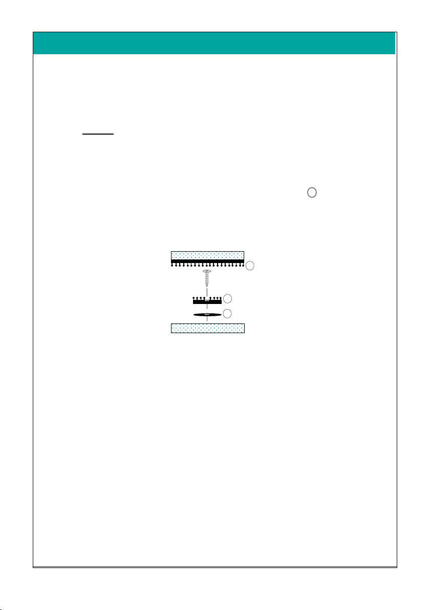
Abb. Fahrerseite
A
C1
D1D2D3
D4
C2C3
Abnehmen der Abdeckblenden:
Die Abdeckblenden können durch vorsichtiges Lösen der Klettverschlüsse
jederzeit abgenommen werden.
VORSICHT:
Bitte jede Art von »gewaltsamem Reißen «an den Blenden
vermeiden (Bruchgefahr !)
1.1. Türverkleidung - Fahrerseite
1.1.1. Fensterscheibe komplett herunterlassen.
1.1.2. Blende (A) in der Innenseite des Türgriffes weghebeln.
1.1.3. Kompletter Türgriff mit Schalterleiste von unten nach nach oben aus der
Verrasterung abdrücken. Darunterliegende 3 Kreutzkopf-Schrauben (C) entfernen.
1.1.4. Torx-Schrauben (D1-3) an der Türverkleidungsunterkante und Torx-Schraube
(D4) an der Türverkleidungsinnenseite entfernen.
1.1.5. Türverkleidung an den unteren und seitlichen Türverkleidungsrändern vorsichtig
(Bruchgefahr!) von den Plastikklipsen abdrücken.
1.1.6. Türverkleidung oben an der Abdichtleiste aus den Klammern herausheben und
gleichzeitig vom Türinnenblech nach oben wegziehen.
1.1.7. Türentriegelungsbautenzug aushängen und alle elektrischen Anschlüsse abstecken.
1.1.8. werkseitiger Lautsprecher demontieren ( wird nicht mehr verwendet)
2.2. Türverkleidung - Beifahrerseite:
2.1.1. Fensterscheibe komplett herunterlassen.
2.2.2. Türgriff-Blende (A1) von unten weghebeln und darunterliegende
2 Kreutzkopf-Schrauben (F1+2) entfernen.
2.2.3. Alle 4 Torx-Schrauben (D1-4) an der Türverkleidungsunterkante und Torx-Schraube
(E) an der Türverkleidungsinnenseite enfernen.
2.2.4. siehe Fahrerseite 1.1.5. - 1.1.8.
46129 - Golf IV “4türig”- 3 - © JEHNERT SOUND DESIGN
46129 - Golf IV “4türig”- 12 - © JEHNERT SOUND DESIGN
1 . Demontage der Türverkleidung:
A1
F1
F2
Die Klettverschlüsse sind ab Werk bereits komplett auf den Abdeckblenden
montiert.
WICHTIG :
Die Klettverschlüsse haften sehr stark!
Die Abdeckblenden deshalb erst nach kompletter Montage der Türpaneele
und Soundsystem fest aufdrücken !
Tipp:
... wenn sich die Abdeckblende an manchen Stellen nicht auf dem
Paneel festdrücken läßt ...
Ursache: Die besondere Formgebung der Türpaneele an dieser Stelle
und die daraus resultierende unterschiedliche Materialstärken
der Abdeckblenden.
Lösung: Mit einer M 4-Unterlagscheibe ø20mm (3) unter dem
Klett-Teller wird dieser Abstand einfach und schnell ausgeglichen:
9. Abdeckblenden
☞
☞
☞
Abdeckblende
2 selbstklebendes Klettband
1 Klett-Druckverschluss
3 Unterlagscheibe M4 ø20 als Distanzhilfe
Türpaneel
Abb. Beifahrerseite
Abb. Fahrerseite
Abb. Beifahrerseite
A
C1
D1D2D3
D4
C2C3
Removing the grills:
The Velcro fasteners stick together very strongly!
The grills can be removed anytime by carefully lifting them off.
Please, avoid any way of forceful yanking at the grills.
It could break!
9.3.
9.2. Our Tip:
If the panel cannot be pressed on completely at some points. . .
Cause: the special form at these points and the resulting differences in
material cross section of the grill.
Solution: the distance can be levelled out with spacers 3 under the
Velcro disc.
(Spacers included with the screw kit)
9.1. Precisely align and carefully press grill into the Velcro fasteners.
The Velcro fastener makes a crackling sound
when it is closed correctly.
1.1. door lining- driver’s side:
1.1.1. remove cover of door handle (inner side- A)
1.1.2. push the complete door handle with switch board and pull away upward.
Remove the underneath 3 crosshead screws (C)
1.1.3. unscrew the 3 Torx- screws (D1-3) on the lower edge of the door lining
and the Torx screw (D4) on the inner side of the door lining
1.1.4. carefully remove the plastic pins of the door lining edges and pull the
door lining away upward unplug power cable for the switch board
2.2. door lining co-passenger’s side:
2.2.1 remove cover of door handle (A1) and unscrew the 2 crosshead screws
( F1+2) underneath
2.2.2. unscrew the 3 Torx- screws (D1-4) on the lower edge of the door lining
and the Torx screw (E) on the inner side of the door lining
2.2.3. carefully remove the plastic pins of the door lining edges and pull the .
door lining away upwards
1 . Disassembly of the door lining
75129 - Golf IV “2-doors”- 3 - © JEHNERT SOUND DESIGN 75129 - Golf IV “2-doors”- 12 - © JEHNERT SOUND DESIGN
A1
F1
F2
☞
9. Installation of the speaker’s grill:
grill
2 self-adhesive Velcro-strip
1 Velcro fastener
3 Washer M4 ø20 as spacer
doorpanel

Verpackungseinheit Checkliste
Türpaneele, bezogen (rechts / links)
Abdeck-Blenden, bezogen (rechts / links)
Hochtöner 26 mm (Montage mit Heißkleber /Silikon)
Mitteltöner 100 mm Q (jeweils mit 4 Blechschrauben am Paneel montiert)
Tieftöner 160 mm (jeweils mit 2 Blechschrauben am Paneel montiert)
Frequenzweichen (rechts / links)
Kleinteile-Beutel:
Schrauben-Senkkopf, M 4 x 30
Schrauben-Senkkopf, M 4 x 40
Schrauben-Senkkopf, M 4 x 50
Schrauben-Senkkopf, M 4 x 60
6-Ktn.Mutter M 4
Unterlagscheiben Ø12mm
Unterlagscheiben Ø20mm als Distanzhilfe für Klettverschlüsse
Blechschrauben, schwarz 3,9x13 (16xf. TT)
Klettband à2,5 cm (Reserve)
Kleinteile-bereits montiert:
Klettverschlüsse + Klettband
Blechschrauben, schwarz 3,9 x 16 f. TT
Blechschrauben, schwarz 3,5 x 16 f. MT
Schrauben-Senkkopf, M 4 x 40
Die Ware wurde sorgfältig verpackt und auf ihre Vollständigkeit geprüft. Bei Fehlmengen, Schäden oder Mängel
beachten Sie bitte unsere Garantieleistungen auf der Rückseite dieser Montageanleitung.
Packliste 46129
46129 - Golf IV “4türig”- 2 - © JEHNERT SOUND DESIGN
2
2
2
2
4
2
6
2
4
2
18
18
2
8
2
je 10
8
8
4
46129 - Golf IV “4türig”- 13 - © JEHNERT SOUND DESIGN
Technische Information
Fahrzeugausstattung: elektrische Fensterheber
Modell/ Modelljahr: 4-türig
Dämmung der Türen: zusätzliche Dämmung der Fahrzeugtüren wird
empfohlen - siehe Seite 8
Einstell-Hinweis: Um den optimalen Raumklang zu erzielen,
sollten am Radiogerät sämltiche Einstellungen
(Bass,Höhen, Loudness usw.) auf Null bzw.
neutral eingestellt werden
empfohlene
Verstärkerleistung: ab 2x 100 - 200 Watt sinus / 2 Ohm
Blechschneidearbeiten: entfallen
Lautsprecherausschnitte/ 2 x 144mm (max.AußenmaßTieftöner 165 mm)
pro Seite (max.Einbautiefe Tieftöner 70 mm)
DIN-Euro-Norm-Korb passend
1 x 92mm (max.AußenmaßMitteltöner 100 mm)
(max.Einbautiefe Mitteltöner 60 mm)
Sound-System: 3-Wege
2 x 160 mm Tieftöner / Seite
1 x 100 mm Mitteltöner / Seite
1 x 26 mm Hochtöner / Seite
fahrzeugspezifische Frequenzweiche
Belastbarkeit Dauer / Musik: 2 x 150/200Watt
Übertragungsbereich: 35-22.000 Hz
Impedanz: 2 Ohm
Änderungen, die dem technischen Fortschritt dienen, bleiben vorbehalten.
!
"
#
!
Loudspeaker wiring diagram
Connect all loudspeakers and crossover circuits:
8. Speaker connection
Insert subwoofer and midrange and connect all loudspeakers
to the crossover circuit (parallel-circuit):
Notice: You should check the polarity of all subwoofers�
before connecting them to the crossover circuit
with a 9 volt battery:
pole of the crossover circuit input to of a 9 Volt battery
pole of the crossover circuit input to of a 9 Volt battery
All subwoofers must move uniformly!
Wrong polarity of a subwoofer can totally
equalize the bass sound!
Packing list ..........................................................................
1. Disassembly of the door lining ..............................................
2. Installation tweeter ..............................................................
3. Paneel alignment / referece points ........................................
4. Handling of door lining / panel installation - fastening ............
5. Lodspeaker cables ................................................................
6. Insulation of the door lining / car door ...................................
7. Installation Crossover + door lining .......................................
8. Speaker connection ..............................................................
Loudspeaker wiring diagram .................................................
9. Installation of the speaker-grill ..............................................
Technical information ...........................................................
Service / fault diagnoses .......................................................
Guarantee ...........................................................................
Packing unit Check list
door panel, covered (right / left) 2
Speaker grill, covered (right / left) 2
tweeter 26 mm 2
tweeter mounting-bowl (with 6Ktn.Screw M4x8,Washer ø12mm) 2
midrange 100 mm Q (each mounted on the panel with 4 Sheet metal-screws) 4
woofer 160 mm (each mounted on the panel with 4 Sheet metal-screws) 16
Crossover (links / rechts) 2
Hardware bag:
$flat head screws, M 4 x 30 10
$flat head screws, M 4 x 40 2
$Spax-screws, 3,0 x 20 2
$Hex nut M 4 18
$Washer Ø 20mm for metric screws 18
$Washer Ø 20mm as s pacer for Velcro fastener 4
$Velcro strip à 2,5 cm (reserve) 4
Preassembled hardware:
%Velcro fastener plus strips 10
%Sheet metal screws, black 3,9 x 13 (for woofer) 16
%Sheet metal screws, black 3,5 x 13 (8x midr.+8x velcro) 16
%flat head screws, M 4 x 30 4
%flat head screws, M 4 x 40 2
The product was carefully packed and checked for its completeness. If you find anything missing, damaged or
defective, please notice our guarantee services on the back of these assembly instructions.
6. insulation of the door lining
Important:
No insulation material behind
- loudspeaker
- door latch lever
- (fig. A): drill a hole for the
installation clip
fig. Driver-side
fig. Co-driver - side
9.1. Precisely align and carefully press grill into the Velcro fasteners.
The Velcro fastener makes a crackling sound
when it is closed correctly.
Removing the grills:
The Velcro fasteners stick together very strongly!
The grills can be removed anytime by carefully lifting them off.
Please, avoid any way of forceful yanking at the grills.
It could break!
9.3.
7. Installation Crossover circuit / doorlining
Packing list 45124/46124
3.1. Place the door lining on a plane surface
3.2. Dismount the loudspeakers attached to the panel for transport protection.
Retain the screws for later assembly.
3.3. Place the panel without loudspeakers and grill on the door lining
and align it:
1. use the fastening angle on the backside of the panel and
the precisely aligned panel as template in order to mark fastening points 1- 9:
•mark the fastening points 1-3 _ premounted in the panel:
pressing the panel to the door lining leaves visible impressions of the screws.
•marking of fixing points 5-9:
use a thin awl to set the marks on the door-lining.
2. draw the speakers’ cut-outs onto the door-lining.
3. remove the panel again. cut out holes for loudspeakers along the marking (see fig.)
with a compass saw.
4. use a 6mm drill for the screws according to the marks set before.
5. Screw in the M4-screws supplied with. Affix the door build to the door-lining.
Screw all 9 x M4-screws only hand-tight .
Secure all screws with the washers and nuts.
6. check again for precise fitting and tighten screws.
7. fixing point 10 - »metal screw 3,0 x 20«:
Use a self-cutting metal screw to level out the doorlining and the other
edges of the panel: Screw horrizontally from the buttom to meet the depht
over the top of the midrange through the doorlining.
2.1. pull off the original tweeter out of the catch in the tweeter triangle and disconnect it.
2.2. Enlarge the original tweeter-cutout to the mounting messurement of the
“JEHNERT-tweeter-bowl” with a plaingrinder.
2.3. connect tweeter with loudspeaker cabel (1,5 - 4mm 2) and lead the cable to
the crossover in the car door (see page 10)
2.4. install the “JEHNERT-tweeter-bowl and the tweeter and affix it with a 6Ktn. screw M4x8
or hot melt adhesive or Silicon.
2.5. insert the tweeter-triangle again.
All cutting edges of the panel must fit to the door lining snugly
all around without gap
7.1. Installation Crossover
7.1.1. precable crossovers - see fig. page 11.
7.1.2. affix the crossover with screws directly on the Aluminium-inner door metal–
- without housing - covered with foamed material *- (see fig).
Check precise fit.
* Important: protect the sheet bar against humidity and observe that the
sheet bar does not touch any metal parts – danger of short circuit!
7.2. Installation doorlining onto the car dor
Check up length of the screws and bolts:
7.2.1. in order to prevent damages of mechanic parts of the car doors, please check
once again the length of all bolts and screws on the back side of the door
lining! No touch with any mechanic parts of the car doors !
(please shorten if necessary).
7.2.2. put the door-lining into the upper sealing of the car door
7.2.3. fit it in contrary order of succession as described on page no. 3
1.1. doorlining - driverside :
1.1.1. pull off the faceplate (A) from the innerside of the door handle and remove it.
1.1.2. afterwards unclip the complete door handle with switch-unit from the buttom to
the top. Disconnect the cable plugs. Remove the 3 crosshead screw (C)
underneath.
1.1.3. Remove all 3 Torx-Screws (D1-3) at the lower edge of the door lining and the Torx-
(D4) at the innerside of the doorlining.
1.1.4. lift the door panel out of the sealing above and simultaneously move it
horizontally and forward away from the inner door metal
1.1.5. unplug the connecting-cable of the switch-unit and original loadspeaker
1.1.6. remove the original speaker and the Bowden pull wire
2.2. doorlining - Co-drivers side:
2.2.1. Unclip the door handle faceplate (A1) from the buttom and remove
the 2crosshead screw (F1+2)
2.2.2. Remove all 4 Torx-Screws (D1-4) at the lower edge of the door lining and the Torx-
Screw (E) at the innerside of the doorlining.
2.2.3. carefully squeeze the door panel away from the plastic clips at the lower
and lateral edges of the door lining and move it horizontally and forward away
from the inner door metal.
fig.: Position crossover
Installation crossover
on the Aluminium-inner door metal
(- not on the doorlining!)
8. Lautsprecheranschluss
Tief- und Mitteltöner einsetzen und alle Lautsprecher mit der
Frequenzweiche verkabeln (Paralell-Schaltung):
Hinweis: Bevor alle Tieftöner an die Frequenzweiche angeschlossen werden,�
sollte die Polarität aller Tieftöner an einer 9 Volt-Batterie
überprüft werden:
Pol des FW-Eingang an von 9 V Batterie
Pol des FW-Eingang an von 9 V Batterie
Alle Tieftöner müssen bei dieser Überprüfung gleichmäßig ausschwingen!
Ein verpolter Tieftöner kann die gesamte Basswiedergabe
aufheben!
8. Lautsprecheranschluss
Tief- und Mitteltöner einsetzen und alle Lautsprecher mit der
Frequenzweiche verkabeln (Paralell-Schaltung):
Hinweis: Bevor alle Tieftöner an die Frequenzweiche angeschlossen werden,�
sollte die Polarität aller Tieftöner an einer 9 Volt-Batterie
überprüft werden:
Pol des FW-Eingang an von 9 V Batterie
Pol des FW-Eingang an von 9 V Batterie
Alle Tieftöner müssen bei dieser Überprüfung gleichmäßig ausschwingen!
Ein verpolter Tieftöner kann die gesamte Basswiedergabe
aufheben!
G u a r a n t e e
9.2. Our Tip:
If the panel cannot be pressed on completely at some points. . .
Cause: the special form at these points and the resulting differences in
material cross section of the grill.
Solution: the distance can be levelled out with spacers 3 under the
Velcro disc.
(Spacers included with the screw kit)
fig.: backside of a door lining – insulation with our article no.: 27000
page
Packing unit Check list
door panel, covered (right / left) 2
Speaker grill, covered (right / left) 2
tweeter 26 mm 2
tweeter mounting-bowl (with 6Ktn.Screw M4x8,Washer ø12mm) 2
midrange 100 mm Q (each mounted on the panel with 4 Sheet metal-screws) 4
woofer 160 mm (each mounted on the panel with 4 Sheet metal-screws) 16
Crossover (links / rechts) 2
Hardware bag:
$flat head screws, M 4 x 30 10
$flat head screws, M 4 x 40 2
$Spax-screws, 3,0 x 20 2
$Hex nut M 4 18
$Washer Ø 20mm for metric screws 18
$Washer Ø 20mm as s pacer for Velcro fastener 4
$Velcro strip à 2,5 cm (reserve) 4
Preassembled hardware:
%Velcro fastener plus strips 10
%Sheet metal screws, black 3,9 x 13 (for woofer) 16
%Sheet metal screws, black 3,5 x 13 (8x midr.+8x velcro) 16
%flat head screws, M 4 x 30 4
%flat head screws, M 4 x 40 2
The product was carefully packed and checked for its completeness. If you find anything missing, damaged or
defective, please notice our guarantee services on the back of these assembly instructions.
1.1. Fensterscheibe komplett herunterlassen.
1.2. Türgriff-Blende (A1) mit einem Keil von unten aus der Verasterung herausdrücken.
Die darunterliegende 2 Kreutzkopf-Schrauben (F1+2) entfernen.
1.3. Alle 3 Torx-Schrauben (D1- 3) an der Türverkleidungsunterkante und
an der Türverkleidungsinnenseite (E) herausdrehen.
1.4. Türverkleidung an den unteren und seitlichen Türverkleidungsrändern vorsichtig
(Bruchgefahr!) von den Plastikklipsen abdrücken.
1.5. Türverkleidung oben an der Abdichtleitste aus den Klammern herausheben und gleich-
zeitig vom Türinnenblech nach oben wegziehen.
1.6. Türentriegelungsbowdenzug aushängen und Stromkabel zur Einstiegsleuchte und
Lautsprecheranschluss abstecken.
4. Handling of door lining / Panel installation - Fastening
2
3
4
5
6
7
8
9
10
11
12
13
14
15
attention – danger !!
No insulation behind the
side-airbags (fig. B)
45124/46124 - VW Passat - 14 - © JEHNERT SOUND DESIGN
45124/46124 - VW Passat - 13 - © JEHNERT SOUND DESIGN
2004/by.AJ/FH - 15 -
Installation instructions
part-no. 45124 /
46124
Jehnert Sound Design
development and
production of
Car-Audio-Systems
Heinrich-Hertz-Str. 11
70794 Filderstadt
Tel.: 0049-711-77 97 87- 87
Fax: 0049-711-77 78 921
e-mail: [email protected]
www.jehnert.com
45124/46124 - VW Passat - 7 - © JEHNERT SOUND DESIGN 45124/46124 - VW Passat - 8 - © JEHNERT SOUND DESIGN
Ausschnitt
Tieftön er
Ausschnitt
Mitteltöner
45124/46124 - VW Passat - 3 - © JEHNERT SOUND DESIGN
45124/46124 - VW Passat - 9 - © JEHNERT SOUND DESIGN
45124/46124 - VW Passat - 11 - © JEHNERT SOUND DESIGN 45124/46124 - VW Passat - 4 - © JEHNERT SOUND DESIGN
45124/46124 - VW Passat - 10 - © JEHNERT SOUND DESIGN 45124/46124 - VW Passat - 12 - © JEHNERT SOUND DESIGN
45124/46124 - VW Passat - 6 - © JEHNERT SOUND DESIGN
45124/46124 - VW Passat - 5- © JEHNERT SOUND DESIGN
3. Panel alignment
45124/46124 - VW Passat - 1 - © JEHNERT SOUND DESIGN
Reference points for fitting:
Only precise alignment of the panel with the door
lining warrants optimal fit.��
1. Reference line 1:
align the outer edge of the panel flush to the edge of the doorlining.
2. Reference line 2:
the lower edge of the panel is parallel to the lower edge of the door lining.
3. Reference line 3:
the upper edge of the panel is parallel to the edge of the doorlinings-inlet.
Circuit diagram of 2-way crossover / 2x subwoofer
45124/46124 - VW Passat - 2 - © JEHNERT SOUND DESIGN
5. Loudspeaker cables
Important tip:
the use of 2x16mm mid-woofer /side may cause vibrations which lead to
annoying rattle noises in the car door
some helpful tips:
• u se our self-adhesive insulation fleece (art.no.: 27000) or a foam material for
the backside of the door lining (see fig. above) or
• s tabilize the backside of the door lining by means of a special material
(Glass Fibre Filler or stiffening material)
important: keep the cut-outs for the door-airbags and speakers open
2. Tweeter Installation - Original tweeter-triangle
1 . Disassembly of the door lining
1 =M 4 x 25
2
= M 4 x 50
!
!
!
!
!
A1
F1
F2
!
!
!
!
!
!
!
Lead 1 speaker cable (1,5 - 4mm 2) from ampli fier into the door.
(Crossover: car door - see page 10)
!
10= screw in metal-Screw 3,0x20
horizontally (!)
9. Installation of the speaker’s grill :
Packing unit Check list
door panel, covered (right / left) 2
Speaker grill, covered (right / left) 2
tweeter 26 mm 2
tweeter mounting-bowl (with 6Ktn.Screw M4x8,Washer ø12mm) 2
midrange 100 mm Q (each mounted on the panel with 4 Sheet metal-screws) 4
woofer 160 mm (each mounted on the panel with 4 Sheet metal-screws) 16
Crossover (links / rechts) 2
Hardware bag:
$flat head screws, M 4 x 30 10
$flat head screws, M 4 x 40 2
$Spax-screws, 3,0 x 20 2
$Hex nut M 4 18
$Washer Ø 20mm for metric screws 18
$Washer Ø 20mm as s pacer for Velcro fastener 4
$Velcro strip à 2,5 cm (reserve) 4
Preassembled hardware:
%Velcro fastener plus strips 10
%Sheet metal screws, black 3,9 x 13 (for woofer) 16
%Sheet metal screws, black 3,5 x 13 (8x midr.+8x velcro) 16
%flat head screws, M 4 x 30 4
%flat head screws, M 4 x 40 2
The product was carefully packed and checked for its completeness. If you find anything missing, damaged or
defective, please notice our guarantee services on the back of these assembly instructions.
T e c h n i c a l i n f o r m a t i o n
Equipment: electric window control
Model / year: 4-doors
insulation: see page 8
Note about setting: To obtain optimal stereoscopic sound, all settings
on the radio (bass, treble, loudness etc) should be
set to zero or neutral.
Recommended
amplifier power : from 2x 100 - 200 Watt sinus / 2 Ohm
Metal cutwork: not necessary
Cut-outs for loudspeaker/ 2 x 144mm (max.outer dimensions woofer 165 mm)
each side (max.installaion depth woofer 70 mm)
Euro-Norm standard basket ø 165 / 6” made to fit
1 x 92mm (max.outer dimensions midrange 100 mm)
(max.installaion depth midrange 60 mm)
Sound-System: 3-ways
2 x 160 mm woofer / side
1 x 100 mm midrange / side
1 x 26 mm tweeter / side
car-customized crossover network
max.continuous Watt/RMS: 2 x 160/300Watt
car specific frequency range: 42-22.000 Hz
Total impedance: 2 Ohm
We reserve the right to make technical changes, as well as development.
C o n t e n t s
Particularly important notes contain the following remarks:
Please follow the installation instructions
“step by step”
and check the package contents
Packing unit Check list
door panel, covered (right / left) 2
Speaker grill, covered (right / left) 2
tweeter 26 mm 2
tweeter mounting-bowl (with 6Ktn.Screw M4x8,Washer ø12mm) 2
midrange 100 mm Q (each mounted on the panel with 4 Sheet metal-screws) 4
woofer 160 mm (each mounted on the panel with 4 Sheet metal-screws) 16
Crossover (links / rechts) 2
Hardware bag:
$flat head screws, M 4 x 30 10
$flat head screws, M 4 x 40 2
$Spax-screws, 3,0 x 20 2
$Hex nut M 4 18
$Washer Ø 20mm for metric screws 18
$Washer Ø 20mm as s pacer for Velcro fastener 4
$Velcro strip à 2,5 cm (reserve) 4
Preassembled hardware:
%Velcro fastener plus strips 10
%Sheet metal screws, black 3,9 x 13 (for woofer) 16
%Sheet metal screws, black 3,5 x 13 (8x midr.+8x velcro) 16
%flat head screws, M 4 x 30 4
%flat head screws, M 4 x 40 2
The product was carefully packed and checked for its completeness. If you find anything missing, damaged or
defective, please notice our guarantee services on the back of these assembly instructions.
Equipment: electric window control
Model / year: 4-doors
insulation: see page 8
Note about setting: To obtain optimal stereoscopic sound, all settings
on the radio (bass, treble, loudness etc) should be
set to zero or neutral.
Recommended
amplifier power : from 2x 100 - 200 Watt sinus / 2 Ohm
Metal cutwork: not necessary
Cut-outs for loudspeaker/ 2 x 144mm (max.outer dimensions woofer 165 mm)
each side (max.installaion depth woofer 70 mm)
Euro-Norm standard basket ø 165 / 6” made to fit
1 x 92mm (max.outer dimensions midrange 100 mm)
(max.installaion depth midrange 60 mm)
Sound-System: 3-ways
2 x 160 mm woofer / side
1 x 100 mm midrange / side
1 x 26 mm tweeter / side
car-customized crossover network
max.continuous Watt/RMS: 2 x 160/300Watt
car specific frequency range: 42-22.000 Hz
Total impedance: 2 Ohm
We reserve the right to make technical changes, as well as development.
We grant a manufacturers gua rantee of 2 years start ing fr om the date of purcha se
of the doo r panels or soun d system f rom the dea ler.
Within this guarantee peri od to our choice we either repair or replace free of
charge all defects due t o materi al or wor kmansh ip.
Exempt from this guarantee ar e damages due t o improper use, wear and t ear or
damages which hav e to be l ed back on wear or interventions by third parties.
The guarantee does not cover subsequent damage s or such defects t hat only
insignif icantly impair the va lue or the usabili ty of the pane ls/sound sy stem.
The guarantee does not cover damages due to external influences.
Panels with additional or wrong assembl y drill holes cann ot be r eturned.
These are damage s to the panel whi ch cannot be r epaired again.
Technical questions Hotline: 0049-711-77 97 87-87
Mirko Schwarz
Development
It is our pleasure to help you!
Marc Sitter
Service
The following notes serve to help troubleshoot and eliminate faults or malfunctions
on your own. If the following measures are not effective, please call us.
What can it be if ... possible cause/ solution
..it doesn’t sound right. wrong polarity on the subwoofers ( page 10)
crosover circuit attached wrong ( page 11)
Doorlining
not cut out ( page 6)
amplifier doesn’t have enough power( page 13)
amplifier connection
...it doesn’t fit correctly. door panel customization ( page 5)
installation of the panels on the door lining (page 6)
.....grills do not hold. observe notes on page 12!
vibrations insulation, see notes on page 8
Self-help and fault diagnosis
!
"
""
"
Final inspection after panel installation:
please check all functions of the operating elements such
as seat adjustment, opening of the glove box,
window winder etc.
reference line 2:
the lower edge of the
panel is parallel to the
lower edge of the door
lining
reference line 1:
outer edge of panel
and doorlining are flush
referece line 3:
upper edge of panel is
parallel to the lower
edge of the doorlinings-
inlet
doorlining:
enlarge the original
cut-ot
2 x 150/200 Watt
35-22.000 Hz

Packliste .............................................................................. 2
1. Demontage der Türverkleidung............................................... 3
2. Montage des Hochtöners im Original-Spiegeldreieck ............... 4
3. Paneelanpassung / Fixpunkte ................................................. 5
4. Bearbeiten der Türverkleidung / Montage der Türpaneele.......... 6
5. Lautsprecherleitungen ........... ............................................... 7
6. Dämmung der Türverkleidung ............................................... 8
7. Montage der Türverkleidung auf die Fahrzeugtüren ................. 9
8. Frequenzweichenmontage + Lautsprecheranschluss ................. 10
Lautsprecheranschluss - Schaltbild ........................................ 11
9. Montage der Lautsprecher-Abdeckblenden ............................. 12
Technische Informationen ..................................................... 13
Service / Fehlersuche............................................................. 14
Garantie ............................................................................. 15
Seite
46129 - Golf IV “4türig”- 14 - © JEHNERT SOUND DESIGN
46129 - Golf IV “4-türig”- 1 - © JEHNERT SOUND DESIGN
Technische Fragen: Info-Hotline: 0711 - 77 97 87 - 87
Wir danken für Ihre Unterstützung !
Mirko Schwarz
Produktentwicklung / Qualität
Durchwahl: - 67
Wir helfen Ihnen gerne weiter!
Sehr geehrter Kunde,
Wir haben uns sehr bemüht unsere neuen Montageanleitungen ausführlicher und
“Schritt für Schritt”zu erklären.
Ihre Tipps und Anregungen helfen uns künftige Unklarheiten oder Fehlinter-
pretationen weiter auszuschließen.
Teilen Sie uns deshalb mit, was Ihnen nicht gefällt oder was wir noch ändern sollten.
Steffen Kretzschmar
Sattlerei / Produktionsablauf
Durchwahl: - 69
Marc Sitter
Versand / Service
Durchwahl: - 68
Marc Sitter
Versand / Service
Durchwahl: - 68
Die folgenden Hinweise sollen Ihnen dabei helfen, Fehler oder Störungen selbst zu
beheben. Wenn folgende Abhilfemaßnahmen nicht greifen, rufen Sie uns bitte an:
Was kann es sein ... mögliche Ursache / Lösung
wenn’s nicht richtig klingt Tieftöner verpolt ( Seite 10)
Frequenzweichen falsch angeschlossen ( Seite 11)
Türverkleidung und Regenschutzfolie
nicht ausgeschnitten ( Seite 9)
Verstärker zu wenig Leistung ( Seite 13)
Verstärker-Anschluss
wenn’s nicht richtig passt Fixpunkte Türpaneelanpassung ( Seite 5)
Montage der Paneele auf die TV ( Seite 9)
Abdeckungen nicht haften Hinweise Seite 12 beachten!
Vibrationsgeräusche Dämmung s. Hinweise Seite 8
Selbsthilfe und Fehlersuche
Inhaltsverzeichnis
Besonders wichtige Hinweise enthalten folgende Markierung:
☞
Bitte folgen Sie den Anweisungen der Montageanleitung
“Schritt für Schritt”
und prüfen Sie den Packungsinhalt
Packliste .............................................................................. 2
1. Demontage der Türverkleidung............................................... 3
2. Montage des Hochtöners im Original-Spiegeldreieck ............... 4
3. Paneelanpassung / Fixpunkte ................................................. 5
4. Bearbeiten der Türverkleidung / Montage der Türpaneele.......... 6
5. Lautsprecherleitungen ........... ............................................... 7
6. Dämmung der Türverkleidung ............................................... 8
7. Montage der Türverkleidung auf die Fahrzeugtüren ................. 9
8. Frequenzweichenmontage + Lautsprecheranschluss ................. 10
Lautsprecheranschluss - Schaltbild ........................................ 11
9. Montage der Lautsprecher-Abdeckblenden ............................. 12
Technische Informationen ..................................................... 13
Service / Fehlersuche............................................................. 14
Garantie ............................................................................. 15
Seite
46129 - Golf IV “4türig”- 14 - © JEHNERT SOUND DESIGN46129 - Golf IV “4-türig”- 1 - © JEHNERT SOUND DESIGN
Technische Fragen: Info-Hotline: 0711 - 77 97 87 - 87
Wir danken für Ihre Unterstützung !
Mirko Schwarz
Produktentwicklung / Qualität
Durchwahl: - 67
Wir helfen Ihnen gerne weiter!
Sehr geehrter Kunde,
Wir haben uns sehr bemüht unsere neuen Montageanleitungen ausführlicher und
“Schritt für Schritt”zu erklären.
Ihre Tipps und Anregungen helfen uns künftige Unklarheiten oder Fehlinter-
pretationen weiter auszuschließen.
Teilen Sie uns deshalb mit, was Ihnen nicht gefällt oder was wir noch ändern sollten.
Steffen Kretzschmar
Sattlerei / Produktionsablauf
Durchwahl: - 69
Marc Sitter
Versand / Service
Durchwahl: - 68
Marc Sitter
Versand / Service
Durchwahl: - 68
Die folgenden Hinweise sollen Ihnen dabei helfen, Fehler oder Störungen selbst zu
beheben. Wenn folgende Abhilfemaßnahmen nicht greifen, rufen Sie uns bitte an:
Was kann es sein ... mögliche Ursache / Lösung
wenn’s nicht richtig klingt Tieftöner verpolt ( Seite 10)
Frequenzweichen falsch angeschlossen ( Seite 11)
Türverkleidung und Regenschutzfolie
nicht ausgeschnitten ( Seite 9)
Verstärker zu wenig Leistung ( Seite 13)
Verstärker-Anschluss
wenn’s nicht richtig passt Fixpunkte Türpaneelanpassung ( Seite 5)
Montage der Paneele auf die TV ( Seite 9)
Abdeckungen nicht haften Hinweise Seite 12 beachten!
Vibrationsgeräusche Dämmung s. Hinweise Seite 8
Selbsthilfe und Fehlersuche
Inhaltsverzeichnis
Besonders wichtige Hinweise enthalten folgende Markierung:
☞
Bitte folgen Sie den Anweisungen der Montageanleitung
“Schritt für Schritt”
und prüfen Sie den Packungsinhalt
Technical questions: Hotline 0049-7158 / 9 56 99-0
!
"
#
!
Loudspeaker wiring d iagram
Connect al l loudspeakers and crossover circuits:
8. Speaker connection
Insert subwoo fer and mi drang e and conn ect all loudspeakers
to t he crossover cir cuit (parall el-circuit):
Notice: You should check the polarity o f all sub woofers�
before connecting them to the crossover circu it
with a 9 volt battery:
pole of the cr ossover circuit input to of a 9 Volt batter y
pole of the cross over circuit input to of a 9 Volt batter y
All sub woofers mu st mo ve uniformly!
Wrong polarity of a subwoofer can totally
equaliz e the bass so und!
Packing list ..........................................................................
1. Disassembly of the door lining ..............................................
2. Installation tweeter ..............................................................
3. Paneel alignment / referece points ........................................
4. Handling of door lining / panel installation - fastening ............
5. Lodspeaker cables ................................................................
6. Insulation of the door lining / car door ...................................
7. Installation Crossover + door lining .......................................
8. Speaker connection ..............................................................
Loudspeaker wiring diagram .................................................
9. Installation of the speaker-grill ..............................................
Technical information ...........................................................
Service / fault diagnoses .......................................................
Guarantee ...........................................................................
Packing unit Check list
door panel, covered (ri ght / lef t) 2
Speaker g rill, c overed (ri ght / lef t) 2
tweeter 26 mm 2
tweeter mounting-bowl (with 6 Kt n.S crew M4 x8,Wa she r ø 12mm ) 2
midrange 100 mm Q (each moun ted on the pa nel with 4 Sheet me tal- sc rews) 4
woofer 160 mm (each moun ted on the pa ne l with 4 Sh eet me tal- sc rews) 16
Crossover (links / rech ts) 2
Hardware bag:
$flat head screws, M 4 x 30 10
$flat head screws, M 4 x 40 2
$Spax-screws, 3,0 x 20 2
$Hex nut M 4 18
$Washer Ø 20mm for me tric screws 18
$Washer Ø 20mm as s pa cer for Velcro fa ste ner 4
$Velcro strip à 2,5 cm (res erve) 4
Preassembled hardware:
%Velcro fastener plus strips 10
%Sheet metal screws, black 3,9 x 13 (for woo fer) 16
%Sheet metal screws, black 3,5 x 13 (8x midr.+8x velcro) 16
%flat head screws, M 4 x 30 4
%flat head screws, M 4 x 40 2
The product was carefully packed and checked for its completeness. If you find anything missing, damaged or
defective, please notice our guarantee services on the back of these assembly instructions.
6. insulation of the door lining
Important:
No insulation material behind
- loudspeaker
- door latch lever
- (fig. A): drill a hole for the
installation clip
fig. D river-side
fig. C o-driver - side
9.1. Precise ly align and ca refull y press gri ll into the Velcro fasteners.
The Velcro fastener makes a crac kling sound
when it is clo sed correctly.
Removing the grills:
The Velcro fasteners stick together very strongly!
The grills can be removed anytime by carefully lifting them off.
Please, avoid any way of forceful yanking at the grills.
It could break!
9.3.
7. Installation Crossover circuit / doorlining
Packing list 45124/46124
3.1. Place the door lining on a pl ane surface
3.2. Dismount the louds peakers at tached to the panel for transport protecti on.
Retain t he screws f or later assembly.
3.3. Place the pan el without loudspeakers and gr ill on the door lining
and align i t:
1. use the fastening angle on the backside of the panel and
the precisely aligned panel as template in order to mark fastening points 1- 9:
•mark the fastening points 1-3 _ premounted in the panel:
pressing the panel to the door lining leaves visible impressions of the screws.
•marking of fixing points 5-9:
use a thin awl to set the marks on the door-lining.
2. draw the speakers’ cut-outs onto the door-lining.
3. remove the panel again. cut out holes for loudspeakers along the marking (see fig.)
with a compass saw.
4. use a 6mm drill for the screws according to the marks set before.
5. Screw in the M4-screws supplied with. Affix the door build to the door-lining.
Screw all 9 x M4-screws only hand-tight .
Secure all screws with the washers and nuts.
6. check again for precise fitting and tighten screws.
7. fixing point 10 - »metal screw 3,0 x 20«:
Use a self-cutting metal screw to level out the doorlining and the other
edges of the panel: Screw horrizontally from the buttom to meet the depht
over the top of the midrange through the doorlining.
2.1. pu ll off the origin al twe eter out of the catc h in the tweeter trian gle and disconnect it.
2.2. En large the original tweeter-cutout to th e mounting me ssurement of the
“JE HNERT-tweeter-bowl” with a plaingrinder.
2.3. connect t weeter with loudspeaker cabel (1,5 - 4m m 2) and lead the ca ble to
the cross over in the car door (see pa ge 10)
2.4. insta ll the “JE HNERT-tweeter-bowl an d the tweeter and affix it with a 6Ktn . screw M4 x8
or hot melt ad hesive or Silico n.
2.5. inse rt t he tweeter-trian gle aga in.
All cutting edges of the panel must fit to the door lining snugly
all around without gap
7.1. Installation Crossover
7.1.1. precable crossovers - see fig. page 11.
7.1.2. affix the crossover with screws directly on the Aluminium-inner door metal–
- without housing - covered with foamed material *- (see fig).
Check precise fit.
* Important: protect the sheet bar against humidity and observe that the
sheet bar does not touch any metal parts – danger of short circuit!
7.2. Installation doorlining onto the car dor
Check up length of the screws and bolts:
7.2.1. in order to prevent damages of mechanic parts of the car doors, please check
once again the length of all bolts and screws on the back side of the door
lining! No touch with any mechanic parts of the car doors !
(please shorten if necessary).
7.2.2. put the door-lining into the upper sealing of the car door
7.2.3. fit it in contrary order of succession as described on page no. 3
1.1. doorlining - driverside :
1.1.1. pull off the faceplate (A) from the innerside of the door handle and remove it.
1.1.2. after wards unclip the complete door h andle with switc h-unit from the buttom to
t he top. Disconnect the cable plugs. Remo ve the 3 cro sshead screw (C)
u nderneath.
1.1.3. Remo ve all 3 Torx-Screws (D1 -3) at th e lowe r edge of the door lin ing and the Torx-
(D4 ) at th e inn erside of the doorlin ing.
1.1.4. lift the door panel out of the sealing above and simultaneously move it
horizontally and forward away from the inner door metal
1.1.5. u nplug the connecting-cable of the switc h-unit and origina l loadspeaker
1.1.6. re move the origin al speaker a nd the Bowden pull wire
2.2. doorlining - Co- drivers side:
2.2.1. Unclip the door handle faceplate (A1) fro m the buttom and remove
the 2cross head scre w (F1+2)
2.2.2. Rem ove all 4 Torx-S crews (D1 -4) at th e lowe r ed ge of the door lin ing and the Torx-
Sc rew (E) at th e inn erside of the doorlin ing.
2.2.3. carefully squeeze the door panel away from the plastic clips at the lower
and lateral edges of the door lining and move it horizontally and forward away
from the inner door metal.
fig.: Position crossover
Installation crossover
on the Aluminium-inner door metal
(- not on the doorlining!)
8. Lautsprecheranschluss
Tief- und Mitteltöner einsetzen und alle Lautsprecher mit der
Frequenzweiche verkabeln (Paralell-Schaltung):
Hinweis: Bevor alle Tieftöner an die Frequenzweiche angeschlossen werden,�
sollte die Polarität aller Tieftöner an einer 9 Volt-Batterie
überprüft werden:
Pol des FW-Eingang an von 9 V Batterie
Pol des FW-Eingang an von 9 V Batterie
Alle Tieftöner müssen bei dieser Überprüfung gleichmäßig ausschwingen!
Ein verpolter Tieftöner kann die gesamte Basswiedergabe
aufheben!
8. Lautsprecheranschluss
Tief- und Mitteltöner einsetzen und alle Lautsprecher mit der
Frequenzweiche verkabeln (Paralell-Schaltung):
Hinweis: Bevor alle Tieftöner an die Frequenzweiche angeschlossen werden,�
sollte die Polarität aller Tieftöner an einer 9 Volt-Batterie
überprüft werden:
Pol des FW-Eingang an von 9 V Batterie
Pol des FW-Eingang an von 9 V Batterie
Alle Tieftöner müssen bei dieser Überprüfung gleichmäßig ausschwingen!
Ein verpolter Tieftöner kann die gesamte Basswiedergabe
aufheben!
G u a r a n t e e
Steffen Kretzschmar
Saddlery / Completion
9.2. Our Tip:
If th e panel can not be pressed on completely at some points. . .
Cause: the special form at these p oints an d the re sultin g differences in
material cross sec tion of the grill.
Solution: the dista nce can be levelled out with sp acers 3 under the
Velcro d isc.
(Spacers include d with the screw kit)
fig.: backside of a door lining – insulation with our article no.: 27000
page
1.1. Fensterscheibe komplett he runterlassen.
1.2. Türgriff-Blen de (A1) m it einem Keil v on unten aus der Verasterung herausdrücken.
Die darunterlieg ende 2 Kre utzkopf-Schrauben (F1+2) entfern en.
1.3. Alle 3 Torx-S chrauben (D1- 3 ) an der Türverkleid ungsunterkante und
an der Türverkleidungsinnenseite (E) herausdrehen.
1.4. Türverkleid ung an den unteren und se itlichen Türverkleidungsrändern vorsichtig
(Bruc hgefahr!) von den Plastikklipsen abdrücken.
1.5. Türverkleid ung oben an der Abdichtleitste au s den Klammern herausheben und gleic h-
zeitig v om Türinnenblech nach oben wegziehen.
1.6. Türentrie gelungsbowdenzug aushängen und Stromkabel zur Einstieg sleuchte und
Lautsprecheranschluss abstecken.
4. Handling of door lining / Panel installation - Fastening
2
3
4
5
6
7
8
9
10
11
12
13
14
15
attention – danger !!
No insulation behind the
side-airbags (fig. B)
45124/46124 - VW Passat - 14 - © JEHNERT SOUND DESIGN
45124/46124 - VW Passat - 13 - © JEHNERT SOUND DESIGN
2004/by.AJ/FH - 15 -
Installation instructions
part-no. 45124 /
46124
Jehnert Sound Design
development and
production of
Car-Audio-Systems
Heinrich-Hertz-Str. 11
70794 Filderstadt
Tel.: 0049-711-77 97 87- 87
Fax: 0049-711-77 78 921
e-mail: sounddesign@jehnert.de
www.jehnert.com
45124/46124 - VW Passat - 7 - © JEHNERT SOUND DESIGN 45124/46124 - VW Passat - 8 - © JEHNERT SOUND DESIGN
Ausschnitt
Tieftön er
Ausschnitt
Mitteltöner
45124/46124 - VW Passat - 3 - © JEHNERT SOUND DESIGN
45124/46124 - VW Passat - 9 - © JEHNERT SOUND DESIGN
45124/46124 - VW Passat - 11 - © JEHNERT SOUND DESIGN 45124/46124 - VW Passat - 4 - © JEHNERT SOUND DESIGN
45124/46124 - VW Passat - 10 - © JEHNERT SOUND DESIGN 45124/46124 - VW Passat - 12 - © JEHNERT SOUND DESIGN
45124/46124 - VW Passat - 6 - © JEHNERT SOUND DESIGN
45124/46124 - VW Passat - 5- © JEHNERT SOUND DESIGN
3. Panel alignment
45124/46124 - VW Passat - 1 - © JEHNERT SOUND DESIGN
Reference points for fitting:
Only precise alignment of the panel with the door
lining w arrants op timal fit.��
1. Reference li ne 1:
align the outer edge of the panel flush to the edg e of the doorlining.
2. Reference li ne 2:
the lower edge of the panel is parallel to the lower edge of the door lining.
3. Reference li ne 3:
the upper edge of the panel is par allel to the edg e of the doorl inings -inlet.
Circuit diagram of 2-way crossover / 2x subwoofer
45124/46124 - VW Passat - 2 - © JEHNERT SOUND DESIGN
5. Loudspeaker cables
Important tip:
the use of 2x16mm mid-woofer /side may cause vibrations which lead to
annoying rattle noises in the car door
some helpful tips:
• u se our self-adhesive insulation fleece (art.no.: 27000) or a foam material for
the backside of the door lining (see fig. above) or
• s tabilize the backside of the door lining by means of a special material
(Glass Fibre Filler or stiffening material)
important: keep the cut-outs for the door-airbags and speakers open
2. Tweeter Installation - Original tweeter-triangle
1 . Disassembly of the door lining
1 =M 4 x 25
2
= M 4 x 50
!
!
!
!
!
A1
F1
F2
!
!
!
!
!
!
!
Lead 1 speaker cable (1,5 - 4mm 2) from ampli fier into the door.
(Crossover: car door - see page 10)
!
10= screw in metal-Screw 3,0x20
horizontally (!)
9. Installation of the s peaker’s grill :
T e c h n i c a l i n f o r m a t i o n
Equipment: electric window control
Model / year: 4-doors
insulation: see page 8
Note about setting: To obtain optimal stereoscopic sound, all settings
on the radio (bass, treble, loudness etc) should be
set to zero or neutral.
Recommended
amplifier power : from 2x 100 - 200 Watt sinus / 2 Ohm
Metal cutwork: not necessary
Cut-outs for loudspeaker/ 2 x 144mm (max.outer dimensions woofer 165 mm)
each side (max.installaion depth woofer 70 mm)
Euro-Norm standard basket ø 165 / 6” made to fit
1 x 92mm (max.outer dimensions midrange 100 mm)
(max.installaion depth midrange 60 mm)
Sound-System: 3-ways
2 x 160 mm woofer / side
1 x 100 mm midrange / side
1 x 26 mm tweeter / side
car-customized crossover network
max.continuous Watt/RMS: 2 x 160/300Watt
car specific frequency range: 42-22.000 Hz
Total impedance: 2 Ohm
We reserve the right to make technical changes, as well as development.
C o n t e n t s
Particularly important notes contain the following remarks:
!
Please follow the installation instructions
“step by step”
and check the package contents
We grant a manufacturers gua rantee of 2 years start ing fr om the date of purcha se
of the doo r panels or soun d system f rom the dea ler.
Within this guarantee peri od to our choice we either repair or replace free of
charge all defects due t o materi al or wor kmansh ip.
Exempt from this guarantee ar e damages due t o improper use, wear and t ear or
damages which hav e to be l ed back on wear or interventions by third parties.
The guarantee does not cover subsequent damage s or such defects t hat only
insignif icantly impair the va lue or the usabili ty of the pane ls/sound sy stem.
The guarantee does not cover damages due to external influences.
Panels with additional or wrong assembl y drill holes cann ot be r eturned.
These are damage s to the panel whi ch cannot be r epaired again.
Technical questions Hotline: 0049-711-77 97 87-87
Mirko Schwarz
Development
It is our pleasure to help you!
Marc Sitter
Service
Marc Sitter
Service
The following notes serve to help troubleshoot and eliminate faults or malfunctions
on your own. If the following measures are not effective, please call us.
What can it be if ... possible cause/ solution
..it doesn’t sound right. wrong polarity on the subwoofers ( page 10)
crosover circuit attached wrong ( page 11)
Doorlining
not cut out ( page 6)
amplifier doesn’t have enough power( page 13)
amplifier connection
...it doesn’t fit correctly. door panel customization ( page 5)
installation of the panels on the door lining (page 6)
.....grills do not hold. observe notes on page 12!
vibrations insulation, see notes on page 8
Self-help and fault diagnosis
!
"
""
"
Final inspection after panel installation:
please check all functions of the operating elements such
as seat adjustment, opening of the glove box,
window winder etc.
re fer e nc e li ne 2:
the lower edge of the
panel is parallel to the
lower edge of the door
lining
re fer e nc e li ne 1:
outer edge of panel
and doorlining are flush
refere ce line 3:
upper edge of panel is
parallel to the lower
edge of the doorlinings-
inlet
doorlining:
enlarge the original
cut-ot

SoundSound
D E S I G N
JEHNERT
!
"
#
!
Loudspeaker wiring diagram
Connect all loudspeakers and crossover circuits:
8. Speaker connection
Insert subwoofer and midrange and connect all loudspeakers
to the crossover circuit (parallel-circuit):
Notice: You should check the polarity of all subwoofers�
before connecting them to the crossover circuit
with a 9 volt battery:
pole of the crossover circuit input to of a 9 Volt battery
pole of the crossover circuit input to of a 9 Volt battery
All subwoofers must move uniformly!
Wrong polarity of a subwoofer can totally
equalize the bass sound!
Packing list ..........................................................................
1. Disassembly of the door lining ..............................................
2. Installation tweeter ..............................................................
3. Paneel alignment / referece points ........................................
4. Handling of door lining / panel installation - fastening ............
5. Lodspeaker cables ................................................................
6. Insulation of the door lining / car door ...................................
7. Installation Crossover + door lining .......................................
8. Speaker connection ..............................................................
Loudspeaker wiring diagram .................................................
9. Installation of the speaker-grill ..............................................
Technical information ...........................................................
Service / fault diagnoses .......................................................
Guarantee ...........................................................................
Packing unit Check list
door panel, covered (right / left) 2
Speaker grill, covered (right / left) 2
tweeter 26 mm 2
tweeter mounting-bowl (with 6Ktn.Screw M4x8,Washer ø12mm) 2
midrange 100 mm Q (each mounted on the panel with 4 Sheet metal-screws) 4
woofer 160 mm (each mounted on the panel with 4 Sheet metal-screws) 16
Crossover (links / rechts) 2
Hardware bag:
$flat head screws, M 4 x 30 10
$flat head screws, M 4 x 40 2
$Spax-screws, 3,0 x 20 2
$Hex nut M 4 18
$Washer Ø 20mm for metric screws 18
$Washer Ø 20mm as s pacer for Velcro fastener 4
$Velcro strip à 2,5 cm (reserve) 4
Preassembled hardware:
%Velcro fastener plus strips 10
%Sheet metal screws, black 3,9 x 13 (for woofer) 16
%Sheet metal screws, black 3,5 x 13 (8x midr.+8x velcro) 16
%flat head screws, M 4 x 30 4
%flat head screws, M 4 x 40 2
The product was carefully packed and checked for its completeness. If you find anything missing, damaged or
defective, please notice our guarantee services on the back of these assembly instructions.
6. insulation of the door lining
Important:
No insulation material behind
- loudspeaker
- door latch lever
- (fig. A): drill a hole for the
installation clip
fig. Driver-side
fig. Co-driver - side
9.1. Precisely align and carefully press grill into the Velcro fasteners.
The Velcro fastener makes a crackling sound
when it is closed correctly.
Removing the grills:
The Velcro fasteners stick together very strongly!
The grills can be removed anytime by carefully lifting them off.
Please, avoid any way of forceful yanking at the grills.
It could break!
9.3.
7. Installation Crossover circuit / doorlining
Packing list 45124/46124
3.1. Place the door lining on a plane surface
3.2. Dismount the loudspeakers attached to the panel for transport protection.
Retain the screws for later assembly.
3.3. Place the panel without loudspeakers and grill on the door lining
and align it:
1. use the fastening angle on the backside of the panel and
the precisely aligned panel as template in order to mark fastening points 1- 9:
•mark the fastening points 1-3 _ premounted in the panel:
pressing the panel to the door lining leaves visible impressions of the screws.
•marking of fixing points 5-9:
use a thin awl to set the marks on the door-lining.
2. draw the speakers’ cut-outs onto the door-lining.
3. remove the panel again. cut out holes for loudspeakers along the marking (see fig.)
with a compass saw.
4. use a 6mm drill for the screws according to the marks set before.
5. Screw in the M4-screws supplied with. Affix the door build to the door-lining.
Screw all 9 x M4-screws only hand-tight .
Secure all screws with the washers and nuts.
6. check again for precise fitting and tighten screws.
7. fixing point 10 - »metal screw 3,0 x 20«:
Use a self-cutting metal screw to level out the doorlining and the other
edges of the panel: Screw horrizontally from the buttom to meet the depht
over the top of the midrange through the doorlining.
2.1. pull off the original tweeter out of the catch in the tweeter triangle and disconnect it.
2.2. Enlarge the original tweeter-cutout to the mounting messurement of the
“JEHNERT-tweeter-bowl” with a plaingrinder.
2.3. connect tweeter with loudspeaker cabel (1,5 - 4mm 2) and lead the cable to
the crossover in the car door (see page 10)
2.4. install the “JEHNERT-tweeter-bowl and the tweeter and affix it with a 6Ktn. screw M4x8
or hot melt adhesive or Silicon.
2.5. insert the tweeter-triangle again.
All cutting edges of the panel must fit to the door lining snugly
all around without gap
7.1. Installation Crossover
7.1.1. precable crossovers - see fig. page 11.
7.1.2. affix the crossover with screws directly on the Aluminium-inner door metal–
- without housing - covered with foamed material *- (see fig).
Check precise fit.
* Important: protect the sheet bar against humidity and observe that the
sheet bar does not touch any metal parts – danger of short circuit!
7.2. Installation doorlining onto the car dor
Check up length of the screws and bolts:
7.2.1. in order to prevent damages of mechanic parts of the car doors, please check
once again the length of all bolts and screws on the back side of the door
lining! No touch with any mechanic parts of the car doors !
(please shorten if necessary).
7.2.2. put the door-lining into the upper sealing of the car door
7.2.3. fit it in contrary order of succession as described on page no. 3
1.1. doorlining - driverside :
1.1.1. pull off the faceplate (A) from the innerside of the door handle and remove it.
1.1.2. afterwards unclip the complete door handle with switch-unit from the buttom to
the top. Disconnect the cable plugs. Remove the 3 crosshead screw (C)
underneath.
1.1.3. Remove all 3 Torx-Screws (D1-3) at the lower edge of the door lining and the Torx-
(D4) at the innerside of the doorlining.
1.1.4. lift the door panel out of the sealing above and simultaneously move it
horizontally and forward away from the inner door metal
1.1.5. unplug the connecting-cable of the switch-unit and original loadspeaker
1.1.6. remove the original speaker and the Bowden pull wire
2.2. doorlining - Co-drivers side:
2.2.1. Unclip the door handle faceplate (A1) from the buttom and remove
the 2crosshead screw (F1+2)
2.2.2. Remove all 4 Torx-Screws (D1-4) at the lower edge of the door lining and the Torx-
Screw (E) at the innerside of the doorlining.
2.2.3. carefully squeeze the door panel away from the plastic clips at the lower
and lateral edges of the door lining and move it horizontally and forward away
from the inner door metal.
fig.: Position crossover
Installation crossover
on the Aluminium-inner door metal
(- not on the doorlining!)
8. Lautsprecheranschluss
Tief- und Mitteltöner einsetzen und alle Lautsprecher mit der
Frequenzweiche verkabeln (Paralell-Schaltung):
Hinweis: Bevor alle Tieftöner an die Frequenzweiche angeschlossen werden,�
sollte die Polarität aller Tieftöner an einer 9 Volt-Batterie
überprüft werden:
Pol des FW-Eingang an von 9 V Batterie
Pol des FW-Eingang an von 9 V Batterie
Alle Tieftöner müssen bei dieser Überprüfung gleichmäßig ausschwingen!
Ein verpolter Tieftöner kann die gesamte Basswiedergabe
aufheben!
8. Lautsprecheranschluss
Tief- und Mitteltöner einsetzen und alle Lautsprecher mit der
Frequenzweiche verkabeln (Paralell-Schaltung):
Hinweis: Bevor alle Tieftöner an die Frequenzweiche angeschlossen werden,�
sollte die Polarität aller Tieftöner an einer 9 Volt-Batterie
überprüft werden:
Pol des FW-Eingang an von 9 V Batterie
Pol des FW-Eingang an von 9 V Batterie
Alle Tieftöner müssen bei dieser Überprüfung gleichmäßig ausschwingen!
Ein verpolter Tieftöner kann die gesamte Basswiedergabe
aufheben!
G u a r a n t e e
9.2. Our Tip:
If the panel cannot be pressed on completely at some points. . .
Cause: the special form at these points and the resulting differences in
material cross section of the grill.
Solution: the distance can be levelled out with spacers 3 under the
Velcro disc.
(Spacers included with the screw kit)
fig.: backside of a door lining – insulation with our article no.: 27000
page
1.1. Fensterscheibe komplett herunterlassen.
1.2. Türgriff-Blende (A1) mit einem Keil von unten aus der Verasterung herausdrücken.
Die darunterliegende 2 Kreutzkopf-Schrauben (F1+2) entfernen.
1.3. Alle 3 Torx-Schrauben (D1- 3) an der Türverkleidungsunterkante und
an der Türverkleidungsinnenseite (E) herausdrehen.
1.4. Türverkleidung an den unteren und seitlichen Türverkleidungsrändern vorsichtig
(Bruchgefahr!) von den Plastikklipsen abdrücken.
1.5. Türverkleidung oben an der Abdichtleitste aus den Klammern herausheben und gleich-
zeitig vom Türinnenblech nach oben wegziehen.
1.6. Türentriegelungsbowdenzug aushängen und Stromkabel zur Einstiegsleuchte und
Lautsprecheranschluss abstecken.
4. Handling of door lining / Panel installation - Fastening
2
3
4
5
6
7
8
9
10
11
12
13
14
15
attention – danger !!
No insulation behind the
side-airbags (fig. B)
45124/46124 - VW Passat - 14 - © JEHNERT SOUND DESIGN
45124/46124 - VW Passat - 13 - © JEHNERT SOUND DESIGN
2004/by.AJ/FH - 15 -
Installation instructions
part-no. 45124 /
46124
Jehnert Sound Design
development and
production of
Car-Audio-Systems
Heinrich-Hertz-Str. 11
70794 Filderstadt
Tel.: 0049-711-77 97 87- 87
Fax: 0049-711-77 78 921
e-mail: sounddesign@jehnert.de
www.jehnert.com
45124/46124 - VW Passat - 7 - © JEHNERT SOUND DESIGN 45124/46124 - VW Passat - 8 - © JEHNERT SOUND DESIGN
Ausschnitt
Tieftöner
Ausschnitt
Mittel töner
45124/46124 - VW Passat - 3 - © JEHNERT SOUND DESIGN
45124/46124 - VW Passat - 9 - © JEHNERT SOUND DESIGN
45124/46124 - VW Passat - 11 - © JEHNERT SOUND DESIGN 45124/46124 - VW Passat - 4 - © JEHNERT SOUND DESIGN
45124/46124 - VW Passat - 10 - © JEHNERT SOUND DESIGN 45124/46124 - VW Passat - 12 - © JEHNERT SOUND DESIGN
45124/46124 - VW Passat - 6 - © JEHNERT SOUND DESIGN
45124/46124 - VW Passat - 5- © JEHNERT SOUND DESIGN
3. Panel alignment
45124/46124 - VW Passat - 1 - © JEHNERT SOUND DESIGN
Reference points for fitting:
Only precise alignment of the panel with the door
lining warrants optimal fit.��
1. Reference line 1:
align the outer edge of the panel flush to the edge of the doorlining.
2. Reference line 2:
the lower edge of the panel is parallel to the lower edge of the door lining.
3. Reference line 3:
the upper edge of the panel is parallel to the edge of the doorlinings-inlet.
Circuit diagram of 2-way crossover / 2x subwoofer
45124/46124 - VW Passat - 2 - © JEHNERT SOUND DESIGN
5. Loudspeaker cables
Important tip:
the use of 2x16mm mid-woofer /side may cause vibrations which lead to
annoying rattle noises in the car door
some helpful tips:
•use our self-adhesive insulation fleece (art.no.: 27000) or a foam material for
the backside of the door lining (see fig. above) or
•stabilize the backside of the door lining by means of a special material
(Glass Fibre Filler or stiffening material)
important: keep the cut-outs for the door-airbags and speakers open
2. Tweeter Installation - Original tweeter-triangle
1 . Disassembly of the door lining
1 =M 4 x 25
2
= M 4 x 50
!
!
!
!
!
A1
F1
F2
!
!
!
!
!
!
!
Lead 1 speaker cable (1,5 - 4mm 2) from amplifier into the door.
(Crossover: car door - see page 10)
!
10= screw in metal-Screw 3,0x20
horizontally (!)
9. Installation of the speaker’s grill :
T e c h n i c a l i n f o r m a t i o n
Equipment: electric window control
Model / year: 4-doors
insulation: see page 8
Note about setting: To obtain optimal stereoscopic sound, all settings
on the radio (bass, treble, loudness etc) should be
set to zero or neutral.
Recommended
amplifier power : from 2x 100 - 200 Watt sinus / 2 Ohm
Metal cutwork: not necessary
Cut-outs for loudspeaker/ 2 x 144mm (max.outer dimensions woofer 165 mm)
each side (max.installaion depth woofer 70 mm)
Euro-Norm standard basket ø 165 / 6” made to fit
1 x 92mm (max.outer dimensions midrange 100 mm)
(max.installaion depth midrange 60 mm)
Sound-System: 3-ways
2 x 160 mm woofer / side
1 x 100 mm midrange / side
1 x 26 mm tweeter / side
car-customized crossover network
max.continuous Watt/RMS: 2 x 160/300Watt
car specific frequency range: 42-22.000 Hz
Total impedance: 2 Ohm
We reserve the right to make technical changes, as well as development.
C o n t e n t s
Particularly important notes contain the following remarks:
Please follow the installation instructions
“step by step”
and check the package contents
We grant a manufacturers guarantee of 2 years starting from the date of purchase
of the door panels or sound system from the dealer.
Within this guarantee period to our choice we either repair or replace free of
charge all defects due to material or workmanship.
Exempt from this guarantee are damages due to improper use, wear and tear or
damages which have to be led back on wear or interventions by third parties.
The guarantee does not cover subsequent damages or such defects that only
insignificantly impair the value or the usability of the panels/sound system.
The guarantee does not cover damages due to external influences.
Panels with additional or wrong assembly drill holes cannot be returned.
These are damages to the panel which cannot be repaired again.
Technical questions Hotline: 0049-711-77 97 87-87
Mirko Schwarz
Development
It is our pleasure to help you!
Marc Sitter
Service
The following notes serve to help troubleshoot and eliminate faults or malfunctions
on your own. If the following measures are not effective, please call us.
What can it be if ... possible cause/ solution
..it doesn’t sound right. wrong polarity on the subwoofers ( page 10)
crosover circuit attached wrong ( page 11)
Doorlining
not cut out ( page 6)
amplifier doesn’t have enough power( page 13)
amplifier connection
...it doesn’t fit correctly. door panel customization ( page 5)
installation of the panels on the door lining (page 6)
.....grills do not hold. observe notes on page 12!
vibrations insulation, see notes on page 8
Self-help and fault diagnosis
!
"
""
"
Final inspection after panel installation:
please check all functions of the operating elements such
as seat adjustment, opening of the glove box,
window winder etc.
reference line 2:
the lower edge of the
panel is parallel to the
lower edge of the door
lining
reference line 1:
outer edge of panel
and doorlining are flush
referece line 3:
upper edge of panel is
parallel to the lower
edge of the doorlinings-
inlet
doorlining:
enlarge the original
cut-ot
Table of contents
Other JEHNERT SOUND DESIGN Car Receiver manuals


Popular Car Receiver manuals by other brands


Blaupunkt
Blaupunkt Palm Beach C51 operating instructions

Blaupunkt
Blaupunkt BPV755 OPERATING AND INSTALLATION Manual

JVC
JVC KW-XG704 Installation & connection manual

Antique Automobile Radio
Antique Automobile Radio 172001B Installation and operating instructions

Antique Automobile Radio
Antique Automobile Radio 422251B Installation and operating instructions

REI
REI system 2000 Tech manual


