Jenaer Antriebstechnik ECOSTEP 54 User manual
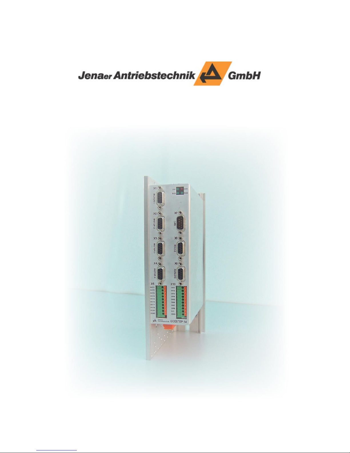
User Manual ECOSTEP®54


Subject to change without notice!
User Manual ECOSTEP®54
3
Edition Comment
Dec 2008 First English edition
Published editions::
All rights reserved:
Jenaer Antriebstechnik GmbH
Buchaer Straße 1
07745 Jena
No parts of this documentation may be translated, reprinted or reproducted on microfi lm or in other ways
without written permission by Jenaer Antriebstechnik GmbH.
e content of this document has been worked out and checked carefully. Nevertheless diff erences from the
real state of the hard and so ware can never be fully excluded. Necessary corrections will be carried out in
the next edition.
ECOSTEP® is a registered trademark of Jenaer Antriebstechnik GmbH, Jena.
Windows® is a registered trademark of Microso Corporation in the United States and other countries.

User Manual ECOSTEP®54
4Subject to change without notice!

Subject to change without notice!
User Manual ECOSTEP®54
5
Inhalt
1 About this manual ......................................................................................................................... 7
2 Safety instructions ......................................................................................................................... 7
2.1 Symbols .........................................................................................................................................................7
2.2 General notes ................................................................................................................................................8
2.3 Dangerous voltages ......................................................................................................................................8
2.4 Danger by hot surfaces ................................................................................................................................8
2.5 Danger by unintentional mechanical movements ...................................................................................8
2.6 Prescribed use ...............................................................................................................................................9
3 Legal notes .................................................................................................................................... 9
3.1 Terms of delivery ..........................................................................................................................................9
3.2 Liability ..........................................................................................................................................................10
3.3 Standards and directives .............................................................................................................................10
3.3.1 UL/CSA compliance acc. to UL 508C .......................................................................................................10
3.3.2 CE compliance ..............................................................................................................................................10
4 Technical Data ............................................................................................................................. 12
4.1 Technical data of the power stage .............................................................................................................. 12
4.2 Electrical connection data ...........................................................................................................................12
4.3 Operating Conditions .................................................................................................................................. 12
4.4 General technical data ................................................................................................................................. 13
4.5 Betriebsarten ................................................................................................................................................. 13
4.6 Suitable types of motors .............................................................................................................................13
5 Installation ................................................................................................................................... 14
5.1 Mounting ....................................................................................................................................................... 14
5.1.1 Important notes ........................................................................................................................................... 14
5.1.2 Dimensions ................................................................................................................................................... 14
5.1.3 Assembly .......................................................................................................................................................15
5.2 Electrical Installation ................................................................................................................................... 16
5.2.1 Important notes ............................................................................................................................................ 16
5.2.2 EMC compliant installation ........................................................................................................................ 16
6 Interfaces ...................................................................................................................................... 17
6.1 Arrangement of the interfaces .................................................................................................................... 17
6.2 Control signals .............................................................................................................................................. 18
6.2.1 X5: Digital outputs, 24 V ............................................................................................................................. 18
6.2.2 X10: Digital inputs .......................................................................................................................................19
6.2.3 X9: Analog inputs, analog output .............................................................................................................. 20
6.3 Power connection .........................................................................................................................................21
6.3.1 X1 to X4: Motor connector .........................................................................................................................21
6.3.2 X11: Supply voltage ...................................................................................................................................... 22
6.4 X8: RS232 interface ...................................................................................................................................... 23
6.5 X7: CAN interface ........................................................................................................................................24
7 Commissioning ............................................................................................................................ 25
7.1 Notes before commissioning ...................................................................................................................... 25
7.2 Control and display elements ..................................................................................................................... 25
7.3 Work schedule commissioning ..................................................................................................................26
7.3.1 Error case ......................................................................................................................................................35

User Manual ECOSTEP®54
6Subject to change without notice!
8 Accessories ................................................................................................................................... 37
8.1 Supplementary parts .................................................................................................................................... 38
8.1.1 Heat sink ........................................................................................................................................................38
9 Annex ........................................................................................................................................... 39
9.1 Flowcharts for PLC programming
9.1.1 Homing ..........................................................................................................................................................39
9.1.2 Operation mode 1 (Profi le Positioning Mode): Direct absolute positioning
(eff ective immediately) ................................................................................................................................ 40
9.1.3 Operation mode 1 (Profi le Positioning Mode): Absolute positioning a er setting
the control word ...........................................................................................................................................41
9.1.4 Operation mode 1 (Profi le Positioning Mode): Relative positioning ................................................... 42
9.1.5 Operation mode 3 (Profi le Velocity Mode) .............................................................................................. 43
9.2 Data Protocol of the RS232 Interface ........................................................................................................ 44
9.2.1 Download Request (Data Transfer from Host to Slave) ......................................................................... 45
9.2.2 Upload Request (Data Transfer from Slave to Host) ............................................................................... 46
9.3 Glossary ......................................................................................................................................................... 47
9.4 Index of standards and directives ..............................................................................................................48
Subject to change without notice!
User Manual ECOSTEP®54
7
1 About this manual
is user manual describes the stepper amplifi er series ECOSTEP®54. It concerns all persons who install,
commission and operate ECOSTEP®54 drives.
Further information:
Programming: manual „Object Dictionary ECOVARIO® and ECOSTEP®“
Motor data: Data sheets series 17S and 23S (stepper motors).
is manual makes the following demands on qualifi ed personnel:
Transport: Personnel trained in handling electrostatic sensitive devices
Installation: Electrotechnically qualifi ed personnel who know the security directives of electrical enginee-
ring and automation
Setup/Commissioning: Qualifi ed personnel with a broad knowlege of the fi elds of electrical engineering,
automation and drives
2 Safety instructions
2.1 Symbols
Table 2.1: Symbols
Pictogram Warning Consequences
General warning about danger Disregarding this warning may
lead to death or serious injuries.
Warning about dangerous electri-
cal voltages
Disregarding this warning may
lead to death or serious injuries.
Warning about hot surfaces Disregarding this warning may
lead to burns to the skin.
User Manual ECOSTEP®54
8Subject to change without notice!
2.2 General notes
Only properly qualifi ed personnel are permitted to perform activities such as transport, in-
stallation, commissioning and maintenance of the ECOSTEP®54.
e manufacturer of the machine must generate a hazard analysis for the machine and take
appropriate measures to ensure that unforeseen movements cannot cause injury or damage
to any person or property.
In case of modifi cations or retrofi ts with components of manufacturers other than Jenaer An-
triebstechnik, please contact us to clarify that those components are suitable to be assembled
with our devices.
Emergency-off equipment must be workable in all operation modes, especially during setup
and maintenance.
2.3 Dangerous voltages
Never open the units during operation. Covers and cabinet doors have to be kept closed du-
ring operation.
e protective earth conductor has to be properly applied before applying a voltage.
During operation logic and power conductors are live. Never undo electrical connections
while they are live!
A er disconnecting the device wait at least 3 minutes before touching contacts. Capacitors
can still have dangerous voltages present up to 3 minutes a er switching off the supply volta-
ge. To be sure measure the DC link circuit and wait till it has fallen below 40 V.
2.4 Danger by hot surfaces
Hot surfaces may cause burns to the skin. As the housing of the ECOSTEP®54 serves also as
heat sink during operation the surface temperature may rise to more than 70 °C.
2.5 Danger by unintentional mechanical movements
Unintentional movements of motors, tools or axes may lead to death or serious injuries.
ECOSTEP®54 drives can produce strong mecanical powers and high accelerations. Avoid
staying in the danger zone of the machine. Never switch off safety equipment! Malfunctions
should be repaired by qualifi ed personnel immediately.

Subject to change without notice!
User Manual ECOSTEP®54
9
2.6 Prescribed use
e stepper motor amplifi ers ECOSTEP®54 are components which are built into electrical equip-
ment or machines and can only be used as integral components of such equipment. All notes about
technical data and ambient conditions have to be observed.
Using the unit in hazardous locations and in ambients containing oil, gas, vapours, dusts, radiati-
ons etc. is prohibited if it is not explicitly allowed.
e manufacturer of the machine must generate a hazard analysis for the machine and take ap-
propriate measures to ensure that unforeseen movements cannot cause injury or damage to any
person or property.
If one or more servo amplifi ers ECOSTEP®54 are built into machines or plants the intended opera-
tion of the servo amplifi er is forbidden until it has been established that the machine or plant fulfi lls
the requirements of the EC Machinery Directive 98/37/EC and the EMC Directive 89/336/EEC.
Further EN 60204 and EN ISO 12100 parts 1 and 2 have to be observed.
3 Legal notes
3.1 Terms of delivery
Our terms of delivery are based on the „ e General Terms of Delivery for Products and Services
of the Electrical Industry“ (German: ALB ZVEI) of the Central Association of the Electrical and
Electronics Industry (ZVEI e.V.) in their current version.

User Manual ECOSTEP®54
10 Subject to change without notice!
3.2 Liability
e circuits and procedures in this manual are proposals. Every user has to check the suitability for every
special case. Jenaer Antriebstechnik GmbH is not responsible for suitability. Especially Jenaer Antriebstech-
nik is not responsible for the following damage causes:
disregarding the instructions of this manual or other documents concerning ECOSTEP®54
unauthorized modifi cations of drive, motor or accessories
operating or dimensioning faults
Improper use of the ECOSTEP®54 components
3.3 Standards and directives
Stepper motor amplifi ers ECOSTEP®54 are components intended to be built in machines or plants for in-
dustrial purposes.
ECOSTEP54 complies to the standards and directives listet in the appendix, chapter 9.4.
3.3.1 UL/CSA compliance acc. to UL 508C
e stepper motor amplifi ers ECOSTEP 54 are designed in compliance with UL or cUL respectively.
For further information see UL fi le number E244038 at www.ul.com.
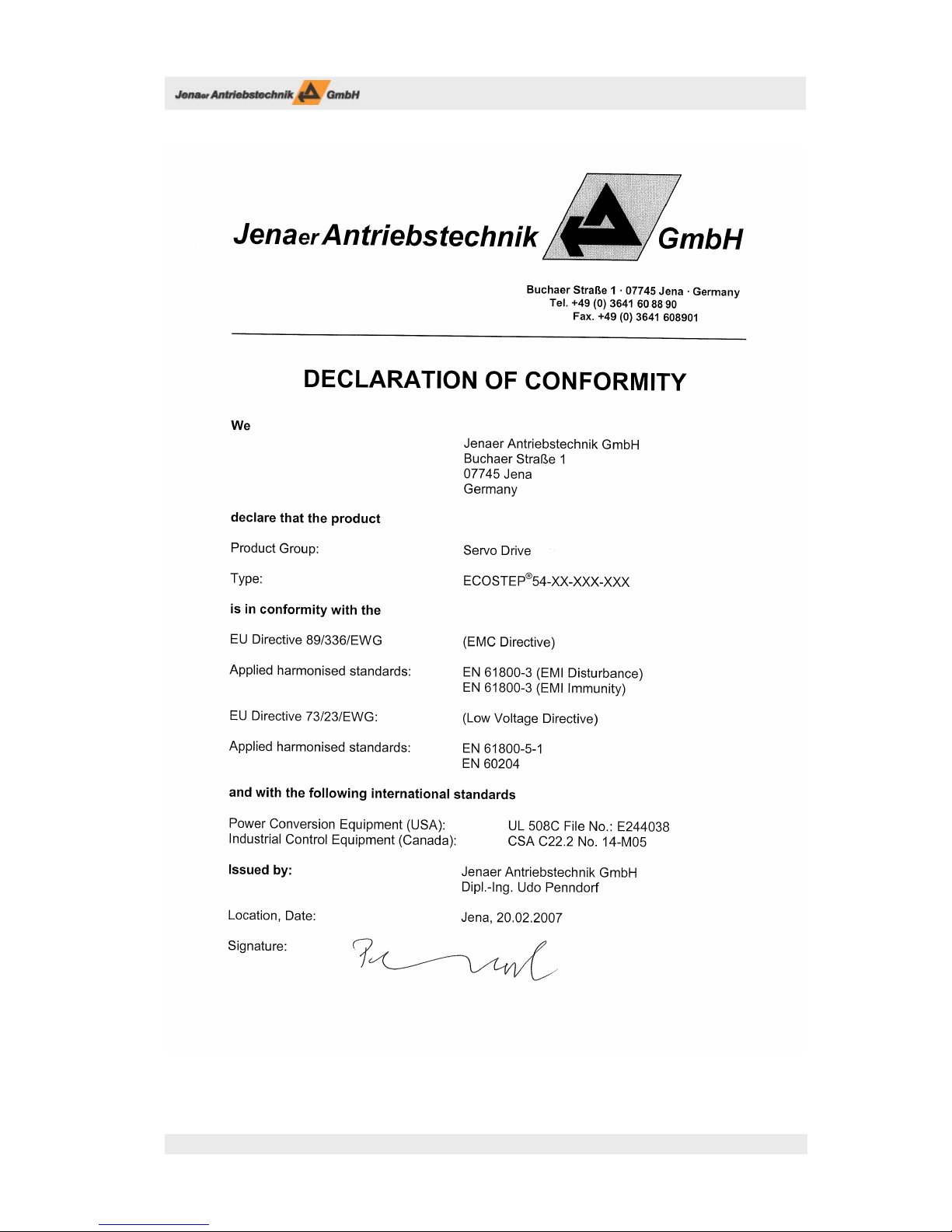
3.3.2 CE compliance
Stepper motor amplifi ers ECOSTEP®54 are components that are intended to be built into electrical plant
and machines for industrial use. e manufacturer of the machine is responsible that the machine or plant
fulfi lls the requirements of the EMC directive.
e stepper motor amplifi ers ECOSTEP®54 have been tested by an authorized testing laboratory in a defi ned
confi guration with the system components which are described in this documentation.
Any divergence from the confi guration and installation described in this manual means that you will be
responsible for carrying out new measurements to ensure that the regulatory requirements are fulfi lled.
Subject to change without notice!
User Manual ECOSTEP®54
11

User Manual ECOSTEP®54
12 Subject to change without notice!
4 Technical Data
4.1 Technical data of the power stage
Table 4.1: Technical data of the power stage
Number of motor outputs 4
Max. phase currrent A 2.5
Step resolution Steps/rev. 12,800
Max. output voltage VDC UDC-BUS , cf. table 4.2
Max. output power W 4 x 100
Short-circuit strength of motor output current limiting in case of short circuit of motor
phases against each other and against UDC-BUS
Minimum inductance of motor winding mH min. 1
Length of motor cable m max. 10*
Frequency of output current ripple dependent on current and inductance
*) Please consult our application department in case of longer cables.
4.2 Electrical connection data
Table 4.2: Electrical connection data
Logic supply VDC 20 ... 30, max. 200 mA
Protection required for logic supply A 3 T
Power supply (UDC-BUS) VDC 24 ... 45
Protection required for power supply A 10 slow-acting*
*) if required, use an UL-certified automatic circuit breaker 10 A, 60 VDC slow-acting
4.3 Operating Conditions
Table 4.3: Operating conditions
Ambient temperature °C 0 ... + 40
Storage temperature °C - 10 ... + 70
Air humidity (non-condensing) 5 ... 95% (RH-2 acc. to IEC 61131-2)
Pollution severity 2 acc. to IEC 61131-2
Protection class IP20
Mounting position vertical
Installation altitude up to 1000 m above mean sea level w/o restriction
Power loss: if 4 axes traverse with 2.5 A W approx. 30
Cooling by means of convection. Heat sink required in case of restricted convection.

Subject to change without notice!
User Manual ECOSTEP®54
13
4.4 General technical data
Table 4.4: General technical data: control signals
No. Control signal Unit
1 24 V supply (current draw without outputs) VDC 24 ±10 %
A 0.8
8
Digital control signal inputs
(user-programmable,
or as limit switch inputs)
VDC LOW 0 – 4, HIGH 13 – 30
mA 3.4 / 2.4 (at 24 VDC)
kΩ 7
1 Control signal DC link relay (REL+, REL-) VDC 20 ... 24
mA 50
8
Digital control signal outputs
(4 user-programmable,
4 resereved for holding brakes)
VDC 24 (20 ... 30)
A0.5
Holding brake: max. 0.8 / 0.4 A
(100 ms / continuous)
4 Analog inputs
0 V ... +5 V, 10 bit resolution
kΩ at DC: R > 250
at f > 250 Hz: R < 15
1 Analog output -10 V – +10 V, 8 bit resolution
Table 4.5: General technical data: dimensions and weight
Dimensions and weight Unit
Dimensions without heat sink
(w x h x d)
mm 240 x 62 x 170 (without mating connector)
Dimensions with heat sink
(w x h x d)
mm 240 x 102 x 170 (without mating connector)
Weight (without heat sink) kg 1.8 kg
Weight (with heat sink) kg 3.4 kg
4.5 Modes for setpoint setting
ECOSTEP®54 provides the following modes for setpoint setting:
Online positioning via fi eld bus (RS232, CANopen)
Positioning control via SPS interface (digital inputs/outputs)
Joystick operation (analog inputs, resolution 10 bit).
4.6 Suitable types of motors
With ECOSTEP®54 stepper motor amplifi er various types of stepper motors can be operated, among others
the stepper motor series 17S und 23S of Jenaer Antriebstechnik GmbH. Technical data and regulations in
this manual only refer to these motors. Technical data of the motors can be retrieved from the motor data
sheets or from our homepage www.jat-gmbh.de.

User Manual ECOSTEP®54
14 Subject to change without notice!
5 Installation
5.1 Mounting
5.1.1 Important notes
Make sure that transport and storage did no damage to the units.
e ambient air must not be polluted by dust, greases, aggressive gas etc. Eventually appropri-
ate countermeasures have to be taken (installation of fi lters, frequent cleaning).
Depending on the power losses an appropriate ventilation should be provided.
Observe the mounting spaces.
At installation locations with permanent vibrations or shocks damping measures should be
taken into consideration.
e device contains electrostatic sensitive devices which can be damaged by improper usage.
5.1.2 Dimensions
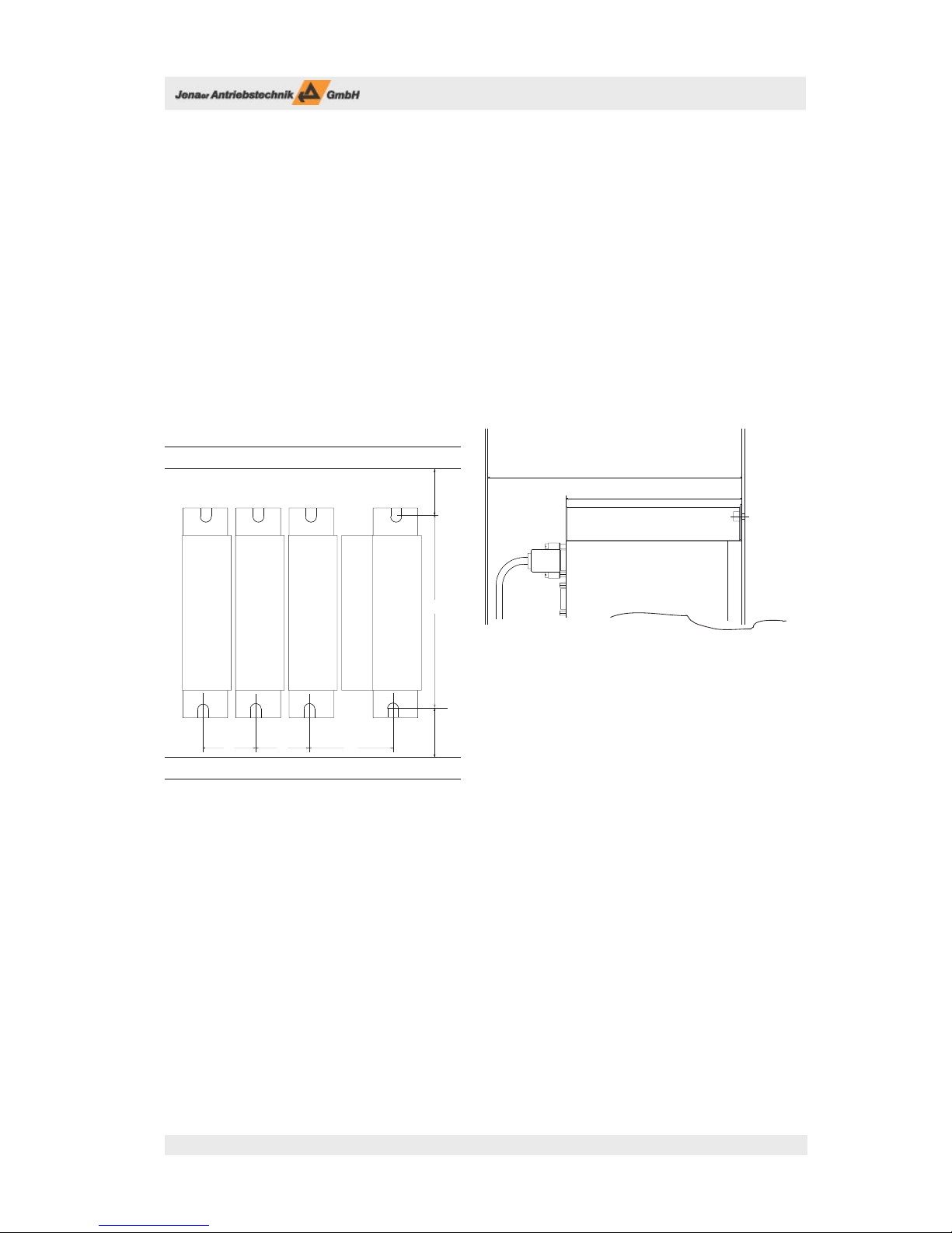
Fig. 5.1: Dimensions of ECOSTEP®54 [mm]
Fig. 5.1: Dimensions of ECOSTEP®54 [mm]
62
240
170
180
Subject to change without notice!
User Manual ECOSTEP®54
15
5.1.3 Assembly
When mounting the ECOSTEP®54 into the cabinet cable clamps (contained in connector kit AMK40, cf.
chap. 8) assure that the connecting cables are laid EMC conform by connecting the cable shield extensively
to chassis earth. Maximum cable diameter is 15 mm.
It is important that the air fl ow is not disturbed by components above or below the stepper motor ampli-
fi ers.
If a heat sink is used (cf. chap. 8.1.1), the mounting space will increase by 40 mm.
e surface of the mounting plate has to be conductive (e.g. zinc plated). Varnished mounting plates must
not be used.
To calculate the minimal mounting depth (fi g. 5.3, dim A) the form of the connectors (cable outlet direction)
and the minimum bending radii of the connecting cables at the sub-D connectors have to be regarded.
Fig. 5.3: Mounting dimensions cabinet, width and depth [mm]
240
1056565
30
30
Cable conduct
Cable conduct
Mounting plate
with conductive
surface
Cubicle door
A
170
Cylindric screw
M5 DIN912

User Manual ECOSTEP®54
16 Subject to change without notice!
5.2 Electrical Installation
5.2.1 Important notes
All installation work may only be carried out if the machine or plant is not live and protected against re-
start.
Never exceed the maximum rated voltage at the connector X11 (power supply) X11! Umax = 45VDC
e guarding of the DC supply and the 24 V logic voltage should be carried out by the user
Stepper motor amplifi er and motor have to be properly grounded. e protective earth conductor must
have at least the same diameter as the supply cables. e stepper motor amplifi er should be mounted onto a
conductive (not varnished) metal mounting plate.
5.2.2 EMC compliant installation
e supply connection of the machine should be equipped with an appropriate RFI suppression fi lter. Al-
ways use shielded cables. Metal parts in the cabinet have to be interconnected extensively and and be con-
ductive regarding HF. Used relays, contactors, solenoids etc. have to be protected against overvoltage. Supply
cables and motor cables must be laid in a proper distance of control cables.

Subject to change without notice!
User Manual ECOSTEP®54
17
6 Interfaces
6.1 Arrangement of the interfaces
Fig. 6.1: Arrangement of the ECOSTEP®54 interfaces
A mating connector for interface X11 (socket connector 6-pole, WAGO type 231-306) is contained in the
connector kit SMK40 (siehe Kap. 9).
Note: e width of the of the D-Sub mating connector handle must not exceed 31.5 mm. (e.g. Harting type
09 67 009 0443).
Fig. 6.1: Arrangement of the ECOSTEP®54 interfaces
Status LEDs
X7: CAN interface
X8: RS232 interface
X9: Analog inputs/outputs
X10: Digital inputs
X11: Power supply
X5: Digital outputs
X1 - X4: Stepper motor
connector 1 ... 4
User Manual ECOSTEP®54
18 Subject to change without notice!
6.2 Control signals
e control signals are programmable (cf. manual „Object Dictionary ECOVARIO® + ECOSTEP®“).
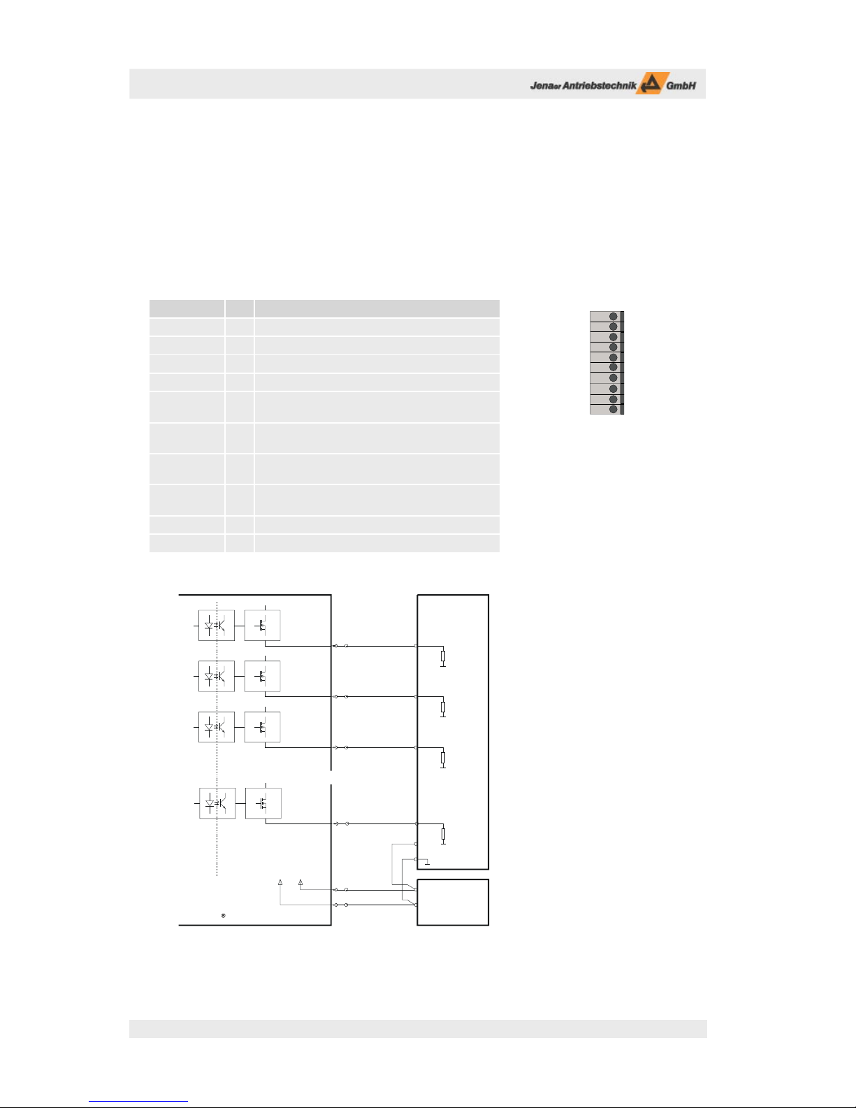
6.2.1 X5: Digital outputs, 24 V
Table 6.1: Pin assignment connector X5
Signal Pin Description
OUT1 1 Digital output 1 (PLC output), IO max = 0.5 A
OUT2 2 Digital output 2 (PLC output), IOmax = 0.5 A
OUT3 3 Digital output 3 (PLC output), IOmax = 0.5 A
OUT4 4 Digital output 4 (PLC output), IOmax = 0.5 A
OUT5 5 Digital output 5, reserved for holding brake motor 1
IOmax = 0.5 A
OUT6 6 Digital output 6, reserved for holding brake motor 2
IOmax = 0.5 A
OUT7 7 Digital output 7, reserved for holding brake motor 3
IO max = 0.5 A
OUT8 8 Digital output 8, reserved for holding brake motor 4
IO max = 0.5 A
O24V 7 24 V supply voltage for digital outputs
OGND 8 24 V ground
Fig. 6.3: Connector X5: Circuit of the digital outputs
Load res.
Load res.
External
power supply
24 VDC
+
-
+24 V
+24 V
+24 V
ECOSTEP 54
Control
Galvanic
isolation
GND +24 V
2
1
Load res.
10
9
X5
OUT1
OUT2
+24 V
GND
+24 V
3OUT3
+24 V
8OUT8
......
Load res.
OUT 1
OUT 2
OUT 3
OUT 4
OUT 5
OUT 6
OUT 7
OUT 8
O24V
OGND
X 5
Fig. 6.2: Connector X5:
10-pole cage clamp terminal
(cable diameter max. 0,752)
Subject to change without notice!
User Manual ECOSTEP®54
19
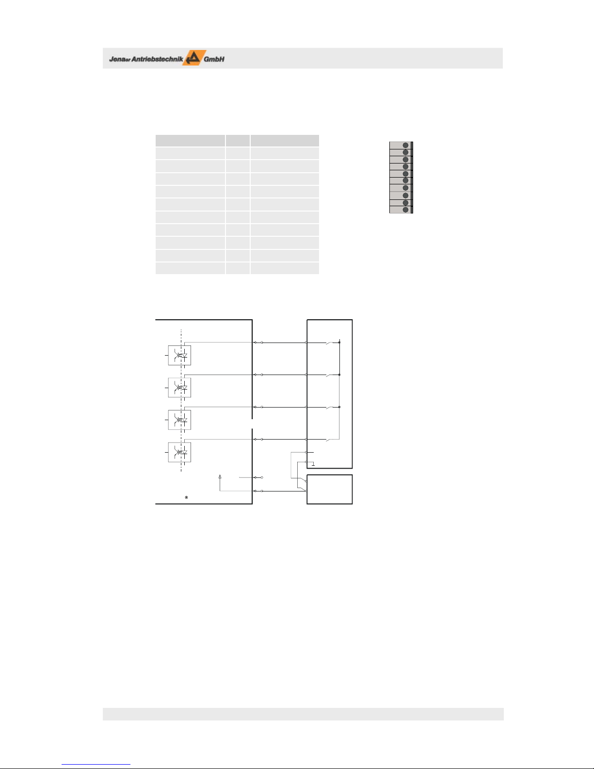
6.2.2 X10: Digital inputs
Tabelle 6.2: Pin assignment connector X10
Signal Pin Description
DIN1 1 Digital input 1
DIN2 2 Digital input 2
DIN3 3 Digital input 3
DIN4 4 Digital input 4
DIN5 5 Digital input 5
DIN6 6 Digital input 6
DIN7 7 Digital input 7
DIN8 8 Digital input 8
n.c. 9 n.c.
IGND 6 external 24V ground
Digital inputs can be used e.g. for limit position switches
Fig. 6.5: Connector X10: Circuit of the digital inputs
Control
24V
IGND
IGND
IGND
IGND
External
power supply
24V=
+
-
24V
ECOSTEP 54
Galvanic
isolation
IGND
IGND
Control signal
DIN1
X10
DIN2
DIN3
DIN8
10
1
2
3
8
9
Control
signal
Control
signal
Control
signal
......
n.c.
DIN4
DIN5
DIN6
DIN7
DIN8
n.c.
IGND
DIN1
DIN2
DIN3
X 10
Fig. 6.4: Connector X10:
10-pole cage clamp terminal
(cable diameter max. 0,752)

User Manual ECOSTEP®54
20 Subject to change without notice!
6.2.3 X9: Analog inputs, analog output
Table 6.3: Pin assignment connector X9
Signal Pin Description Value
AN0 1 Analog input 1 0 ... 5 V
AN1 2 Analog input 2 0 ... 5 V
AN2 3 Analog input 3 0 ... 5 V
AN3 4 Analog input 4 0 ... 5 V
GND 5 Internal GND
+5V 6 Internal 5-V-supply max. load 20 mA,
unprotected!
n.c. 7 n.c.
DA0 8 Analog output +/- 10 V
GND 9 Internal GND
Fig. 6.7: Connector X9: Circuit of the analog inputs and the analog output
6 7 8 9
1 2 3 4 5
Fig. 6.6: Mating connector X9:
9-pole D-Sub connector,
View of the solder or crimp side
+5V
GND
Power supply
6
1
4
10k
1k
2V
GND
ECOSTEP 54
X9
Control
GND
5
9
8
+5V
AN0
GND
GND
AN3
DA0
10k
GND
+5V
GND
+5V
+5V
GND
Analog value
+
-
880k
220k
0...5V
DAC
+5V
+5V ......
...
Table of contents
Popular Amplifier manuals by other brands


Peavey
Peavey CS 400x operating guide

Marantz
Marantz ZS5300 Specifications

Pioneer
Pioneer SCU-M2096ZH Service manual

Rockford Fosgate
Rockford Fosgate Punch P200.2 Installation & operation instructions

Extron electronics
Extron electronics Extron P/2 DA2xi user guide

Acoustic
Acoustic Class D NEO Dymium Series owner's manual