Jensen Audio Power 2000.1 D User manual

POWER
Amplifiers
Power
2000.1
D
Installation
&
Operation
Manual
Amplificadores
Power
Manual
de
lnstalacion
y
Operacion
Amplificateurs
Power
Manual
de
Installation
et
Operation
Contents
Contenido
Table
des
matieres
Introduction
....
.
........................
1
lntroducci6n
............................
13
Introduction
..................
.
.........
25
Features
and
Specifications
...............
2 Caracteristicas y
Especificaciones
.........
14
Fonctions
et
specifications
...............
26
Installation
..............................
3
lnstalaci6n
..............................
15 Installation
.............................
27
Power
Wiring
...
..
.......................
4 Cableado
de
Energia
.....................
16 Cablage
puissant
........................
28
Speaker
Wiring
...............
.
..........
6 Cableado
de
Altavoz
.....................
18 Cablage
des
haut
parleurs
................
30
Input
Wiring
.......
..
.........
.
...
...
....
7 Cableado
de
Entrada
.....................
19 Cablage
d'
Entree . . . . . . . . . . . . . . . . . . . . . . .
31
Indicators
and
Controls
.........
.
.........
8
lndicadores
y
Controles
..................
20
lndicateurs
et
controles
..................
32
Testing
.................................
9 Testeo
.................................
21
Essais
.................................
33
Remote
Input
Level
Control
................
9
Control
de
Nivel
de
Entrada Remoto
........
21
Controle
du
niveau d'entree a
distance
.....
33
Troubleshooting
........................
10
Localizaci6n
de
Problemas
................
22 Depannage
.............................
34
CEA
Power
Output
. . . . . . . . . . . . . . . . . . . . . .
11
Salida
de
Energia
CEA
....................
23
Sortie
de
puissance
CEA
.................
35

Power
Amplifiers
11

Introduction
The Jensen Power series
of
amplifiers were designed to meet
or
exceed the
CEA-2010 test standards. These new standards give all participating
manufacturers (and many don't participate) a baseline when comparing
amplifiers
of
similar power output. The
CEA
Power rating protects you, the
customer. "Power is
power-
itdoesn't matterwho makes it," is not always true.
What does matter is whetherthe power can be produced in the first place. The
RMS rating is the true poweryou are getting.
At
Jensen, to be fair to you and to
the competition, we rate
our
amps in the two most popular ratings, including
the
CEA
RMS rating. So feel confident that your Jensen purchase decision
was a sound one, and remember
"If
it's Too Loud, You're Too Old."
Before You Begin
We need to getthe legal stuff out
of
the way, so please keep reading.
Afterwards, you'll be armed with the knowledge to install your
new
hard-hitting,
speaker-pumping Jensen amplifier.
Exposure to loud sounds
or
music can permanently damage your hearing.
Unfortunately,
in
many cases, the damage is not noticeable until years later.
In
addition, loud music may hinder your ability to hear traffic, police, and fire
or
emergency vehicles. Please be responsible and have respect for other people
by listening at moderate volumes!
Warranty Service
If
your Jensen amplifier should ever require service, you will need the original
dated receipt.
If
you must return the unit for any reason, always include the
receipt with the product.
POWER
Amplifiers
1

POWER
Amplifiers
Features
and
Specifications
Your
new
Jensen Power mobile
mono
power
amplifier
is
the
amplifier
of
choice
for
the
high demands
of
auto
sound reproduction.With its deep-bass
reproduction and
plenty
of
reserve power,
low
harmonic
distortion
and neutral
reproduction,
the
Powerseries
of
amplifiers takes
Mobile
Hi-Fi
to
new
heights.
Like all Jensen products,
when
it
comes
to
accurate sound reproduction
the
Power series takes a backseat
to
no
one.Jensen
will
bring
your
Hi-Fi
experience
to
new
heights
with
the
following
features:
•
MOSFET
Output
and Power Supply
·Optimized
Class
D Design Minimizes Distortion and Reduces Idle Current
• Easily Drives
1-0hm
Loads
• Pass-Thru
RCA's
•Variable
Bass
EQ
0
-12dB@
45Hz
• 12dBI Octave Low
Pass
and High
Pass
filters
·Variable
Input
Level400mV-
4V
·Short
Circuit, DC-offsetandThermal Overload Protection Circuitry
• Diagnostic
LED's
-Green: Power,
Red:
StandbyI Fault
•
Mono
Subwoofer
Amp
• Low
Pass
Filter40 -300
Hz,
12dBI octave
·Subsonic
Filter
16-40Hz,
12dBI octave
·Remote
Input
Level Control (Remote
Bass
Control)
with
5
Meter
Interface
Cable
•
Phase
Switch 0 - 180 degrees
·Signal
to
Noise@
120Hz:>
1
OOdB
(Rated Power)
·Channel
Separation
Not
Applicable
•THD+N @1Watt: 0.02%, 125
Hz,
14.4VDC
Power Output
•
RMS
Power
Output@
2%
THD+N, 1kHz, 14.4VDC
•450 x 1Watts,
4-0hm
• 725x 1Watts,
2-0hm
• 1000x 1Watts,
1-0hm
Specifications subject
to
change
without
notice.
2

Installation
Before you begin the installation
of
your Power series amp remember, there
are two ways to do things -right and twice! Use the proper installation
techniques, tools and accessories to ensure that your Jensen Power series
amp will put out all the power it was designed to.
If
necessary, seek a
professional installer to have the amplifier installed correctly. Most mobile amp
installations do not have the proper gauge wire for power and ground -do not
let your amp be a victim
of
this common installation oversight!
NOTE: This device
is
a
high-power
audio
amplifier
intended
for
installation in vehicles with a 12-Voltnegative
ground
electricalsystem.
Attempting
to
connect
or
operate the
amplifier
with
another
type
of
electricalsystem
may
cause damage
to
the
amplifier
or
the electrical
system.
Installation
Assistance
For installation assistance, call1-800-323-4815 during normal business hours,
or
visit www.jensen.com at any time.
Supplies
and
Tools Needed
To
install the amplifier, you will need tools, supplies and adapters. It is best to
make sure you have everything you need before you start.
Supplies
o Black electrical tape
o Amplifier Installation Kit
Tools
o Cordless drill with assortment
of
bits
o Flat-head and Philips screwdrivers
o Wire cutters/strippers
o Crimping tool
o 12-volt test light
or
digital multimeter
o Wire brush, sandpaper
or
scraping tool (ground connection to vehicle should
be a clean, unpainted metal surface)
3
POWER
Amplifiers
Disconnect
Battery
Disconnect the negative(-) battery cable before starting the installation. Check
the battery ground (there should be two (2) ground wires coming from the
battery -one going to the starter mounting bolt
or
engine block and another
going to the vehicle chassis) and make sure the battery is grounded to the
chassis with at least a #4 gauge wire. Also check the alternator connections,
making sure they are tight and free from corrosion, rust
or
dirt.
Location
and
Mounting
The amplifier's compact design allows great flexibility in mounting. Common
mounting locations include underthe front passenger seat
or
in the trunk area.
When selecting a location, remember that amplifiers generate heat. Select a
location on a flat surface away from heat and moisture where air can circulate
around the amplifier.
Place the amplifier in the mounting location and markthe positions
of
the holes
with a marker, pen
or
pencil. Carefully drill the mounting holes in the marked
positions, then use the supplied mounting screws to securely fasten the
amplifier to the mounting surface.
WARNING: Do
not
cover
the
amplifier
with
carpets
or
enclose
it
behind
interior
trim panels,
and
do
not
mount
the
amplifier
in an inverted
or
upside down configuration. Be
sure
the
mounting
location
and
the
drilling
of
pilot
holes
will
not
damage
any
wires,
control
cables, fuel
lines, fueltanks,
hydraulic
lines
or
other
vehicle
systems
or
components.
Routing
Wires
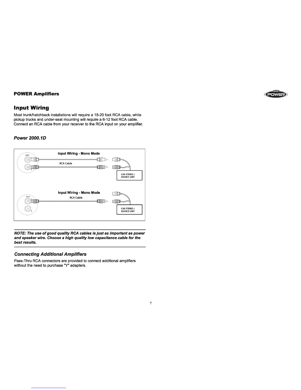
Properwiring connections are illustrated on the following pages.
If
wiring
connections are made incorrectly, the unit will not operate properly and could
become permanently damaged. Follow the installation instructions carefully,
or
have the amplifier installed by an experienced technician.

POWER
Amplifiers
Power
Wiring
Charging System
In some
cases
,
the
installation
of
just
one
(1)
amplifiercould
be
enough
to
overload
your
factoryelectricalsystem
(i
.e.,alternator).Depending
on
the
state
of
your
electricalsystem and overallcondition
of
your
vehicle, you may
need
to
upgradeyouralternatorand battery. After
the
vehicle
is
started,
the
alternator provides
the
power
to
your
electricalsystem,
not
the
battery.When
the engine is running,
the
alternator
is
yourmain source
of
power.Upgrading
the alternatorshould be
your
firstconsiderati
on
if
you shouldexperiencea
voltage
drop
in
the
system
when
operating youraudio system. Adding
capacitors and/orbatteries
without
upgrading
the
alternator
will
only
make
the
problem worse because these devices
put
an extra load
on
the
alternator. After
upgrading
the
alternator,capacitors
and/or
batteri
es
can
be
installed
if
desired.
Use
the
following recommended wiregauge
as
a
gu
i
de
when
installing
your
amplifier(s):
MODEL NUMBER
MAX
CURRENT DRAW MIN WIRE GAUGE
2000.
10
105A #4
4
Power
Terminal (+12VIB+)
Connect
the
main powerwire
to
the
battery,
within
18inches from
the
positive
(+) batterypost,using
an
adequatesize fuse
or
circuitbreakercapable
of
handling
the
current
of
the
selected
power
wire.Afuse
or
circuitbreaker must
be
installed
to
preventa possibleelectrical fireshould
the
main powerwire
shortto ground.
, - -
--------1
I Fuse
or
Circuit
Bl9ker
:
I I
I I
~::::
==:::;:
::::CL
I
I
1 Install as close
to
the
I
I
battely
as
possible.
I
l_ _
________
j
Remote Terminal (REM)
Connect
the
powerantenna
or
amplifier
turn
-
on
lead
from
the
receiver
to
the
amplifierremoteterminal.
-POWER
INPl/T
-
RemoteTurn-On (PowerAntenna)

Ground Terminal (GND)
Make the ground lead as short as possible, leaving enough length to complete
the installation and to allowfor any service that may be needed at a later date.
To
ensure a good ground, scrape away any paint
or
undercoating to expose
bare metal. Use a "ring" terminal
of
the proper gauge and an "outside star
washer'' (between the chassis and ring terminal) when making your ground
connection. Although you've scraped away the paint to expose bare metal, the
outside star washer will help to "bite into" the chassis for a tight, secure
ground.
-POWER
INPUT
-
+12V
REM
GND
T
'
©>=====~~
Drill hole in chassis sheet metal.
Replacement Fuse Requirements (FUSE)
Model Quantity Amps Type
2000.10 3 35 ATO
POWER
Amplifiers
5

POWER
Amplifiers
Speaker
Wiring
The Speaker Wiring diagrams illustrate options for connecting one
or
two
speakers. Observe the proper speaker polarity.
NOTE:
Power
amplifiers can drive speakers
with
a
nominal
impedance
range
of
1-
4-ohms.
For
maximum power, configure
your
speakers
for
a
nomina11-ohm load.
NOTE: Do
not
overlook
the use
of
the
proper
gauge speakerwire. The
Power
series
of
amplifiers require a
minimum
of
12-gauge wire.
Power
2000.1D
Two Subwoofer
SPEAKER OUTPUT
4ohm
4ohm
One Subwoofer
SPEAKER OUTPUT
4 ohm nominal
6

POWER
Amplifiers
Input
Wiring
Most trunk/hatchback installations will require a 15-20 foot RCA cable, while
pickup trucks and under-seat mounting will require a 6-12 foot RCA cable.
Connect an RCA cable from your receiver to the RCA input on your amplifier.
Power
2000.1D
InputWiring -Mono Mode
RCA
Cable
InputWiring -Mono Mode
RCA
Cable
NOTE: The use
of
good
quality
RCA cables
is
just
as
important
as
power
and
speakerwire. Choose a
high
quality
low
capacitance cable
for
the
best
results.
Connecting
Additional
Amplifiers
Pass-Thru RCA connectors are provided to connect additional amplifiers
without the need to purchase "Y" adapters.
7

POWER
Amplifiers
Indicators
and
Controls
PowerIndicator (POWER)
The power indicator provides a visual indication that the amplifier
is
turned on.
Input Level Control (LEVEL)
The input LEVEL control matches the output
of
your radio to the input
of
the
amplifier. After the installation
is
complete, make sure the input level control on
the amplifier is turned down all the way (counter-clockwise orall the way to the
left). Play a tape or CD (make sure bass and treble settings or Bass EQ are
flat) and turn the volume up slowly until you just start to hear distortion. Back
the volume down just a bit.
On
the amplifier, slowly turn up the input level
control (clockwise orto the right) until you just start to hear distortion, then
back it down a bit. Now your radio and amplifier levels are matched.
BASSEQ
The Bass EQ
is
continuously adjustable from 0 to
+12dB@
45Hz. Adjusting
the Bass Boost level allows different subwoofer/enclosure combinations to be
equalized. Use this control to increase the level
of
low bass available from your
subwoofer/enclosure combination. Ported and Band Pass enclosures should
be
limited to about +6dB to +9dB
of
boost. Sealed enclosures should be able
to accept the full +12dB
of
boost,
if
necessary. The full +12dB
of
boost should
be reserved for special applications since improper use
of
the Bass Boost
could damage your subwoofers at high volumes.
Low
Pass Filter(LPF)
The Low Pass Filter controls adjust the crossover point. Typical crossover
is
between 60Hz and 80Hz for ported and sealed enclosures. Bandpass boxes
will typically use a higher crossover setting between 125Hz and 150Hz. Since
musical tastes vary, you should play music that you would normally listen to
in
yourvehicle, with the above settings as a starting point. If necessary, set the
crossover by ear.
High Pass Filter (HPF)
The high pass filter will limit the low frequencies being transmitted to your
speakers. This can
be
useful
in
number
of
situations. For example,
if
you
selected the high pass filter and set the crossover to 40Hz, then you would
have an infra-sonic (sub-sonic) filter at 40Hz, which would be useful with
certain enclosure/subwoofer combinations that were tuned between 45Hz and
50Hz. Other uses might include limiting the low frequencies to smaller
8
speakers (6 1/2", 6 X 9", etc.) by adjusting the crossover to a highersetting
(80-1
OOHz).
Phase Switch
The
Phase
Switch
is
selectable
to
0
degrees
(normal
polarity)
and
180
degrees
(inverted polarity).
Depending
on
the
size
and
location
of
your
subwoofer
and
main
speakers,
you
may
need
to
adjust
the
Phase
Switch
to
provide
the
best
blend in
the
midbass
(60 -150Hz).
To
determine
the
appropriate
phase
setting,
select
either
regular
(0°)
or
inverted
(180°)
and
perform
a
sound
test. Listen
carefully
to
the
sound
quality
while
playing a
CD
with
male
voices
and/or
low
bass
such
as
percussion
or
bass
lines,
then
select
the
position
that
produces
the
fullest
and
most
dynamic
bass. You
may
need
to
adjust
the
Input
Level Control
and
the
Low
Pass
Filter control
after
setting
the
Phase
Switch.

«S»
)
Testing
Before finishing the installation, perform the following tests to make sure the
wiring is correct and everything is operating properly.
Reconnect Battery
When wiring is complete, reconnect the battery negative terminal.
Test Power Wiring
Turn on the receiver, but do not turn up the volume. The amplifier power light
should come on. If not, check the REM and +12V (B+) wires. Turn up the
receiver volume slightly. All speakers should operate.
If
not, check wiring
connections at amplifier and speakers.
Test Speaker Connections
These tests make sure the speakers are connected properly. Ifspeakers don't
play at all, one (or both) speakerwires may be disconnected.
9
POWER
Amplifiers
Remote
Input
Level
Control
The Power 2000.1 D comes equipped with a Remote Input Level Control.
The
Remote Input Level Control allows the input level to be adjusted from an
alternate location. It can be mounted under-dash
or
in-dash. When the
amplifier is used to drive subwoofers and the low pass crossover is activated,
the Remote Input Level Control can be used as a "remote bass level control".
This enables you to control the bass level independent from the rest
of
the
system. This is convenient for system tuning and/orwhen playing many
different types
of
music.
The Remote Input Level Control uses a 3.5mm modular cable for connectivity.
Simply plug the 3.5mm modular cable into the amplifier and then into the
Remote Input Level Control to activate the circuit.
0 INPUT REMOTE
GAIN
LPF
SUB
BASS
PHASE
OUTPUT 0
SONIC
BOOST
p_.
ooooo.~Q,
"'"
~-
""~'"~
...
~•
''"
,,t
o' 00 R
.0
..

POWER
Amplifiers
Troubleshooting
Problem
Possible
Cause
Amplifier does not No power to +12V
turn on terminal
No powerto REM
terminal
Blown main fuse at
battery
Blown fuse at amplifier
Faulty ground
Volume control too Input level control
sensitive adjusted too high
Distorted sound Input level control
adjusted too high
Blows fuse(s) at amp Power wires connected
backwards
Internal problem with
amp
Engine noise I Ground loop(s)
Alternator whine Faulty ground at amp
Faulty ground at head
unit
Inductive coupling
Input level on amp set
too high
Thermal protection Amplifier driving 1 ohm
activated load for long durations
Corrective
Action
Check fuse(s)
Check head unit fuse(s) and
wiring
Replace fuse and identify
cause
of
failure
Replace fuse and identify
cause
of
failure
Re-ground main power
ground to bare metal
chassis
Re-adjust the input level
(referto page 8)
Re-adjust the input level
(refer to page 8)
Reconnect power wires
properly
Take unit for service
Use good quality shielded
RCA cables
Re-ground amp to clean
bare metal chassis
Re-ground head unit to
clean bare metal chassis
Re-route RCA and/or
speaker wires away from
factory harnesses
Re-adjust input level (refer
to page 8)
Ifthe amplifier "thermals"
frequently while driving
subwoofers, install fan to
keep amp cool.
10
Short circuit Blown speakers Check all speakers
protection activated Speaker wire(s) shorting Check for faulty wiring
to ground
Defective crossover Faulty passive crossover
Low impedance Amp connected to Check speaker connections
protection activated improper load
Amp will not drive less Verify that speakers are
than a 1 ohm load connected properly
Speakers defective/ Check speakers
blown
Faulty passive Check crossovers
crossovers
Poor bass response Speakers out
of
phase Check speaker polarity;
reverse the connection to
one speaker only
if
two
subwoofers are connected
to the amplifier.
NOTE:
If
the
protection
light
is
activatedwith
no
speakers connected to
the amplifier,
and
all
the
power
connections are correct,
this
would
indicate an internal
problem
with
the amplifier.

CEA
Power
Output
RMS Power
Output@
1%
THD+N, 14.4VDC
Power
2000.1D
Power
Output: 425 watts RMS X 1 channels into
4-ohms@
< 1% THD+N
Signal
to
Noise Ratio: 100dBAbelow reference (Reference: 1 watt, 4-ohms)
Additional
Power
Output: 675 watts RMS X 1 channels into 2-ohms @ < 1% THD+N,
900 watts RMS X 1 channel into 1-ohms @ < 1% THD+N
Frequency
Response: 10Hz to 300Hz, -3dB (Reference: 1 watt)
Dimensions:
L 11.3" x H 2.0" x W 8.1"
Weight: 6.3 lbs
POWER
Amplifiers
11

Limited
Warranty
Audiovox
Electronics Corporation
("the
Company")
is
committed
to
quality
and
customer
service, and are pleased
to
offer
you
this
Warranty. Please read
it
thoroughly
and
contact
the Company at 1-800-
323-4815
with
any
questions.
Who
is
covered?
The Company extends this warranty to the original
retail
purchaser
of
products
purchased through
an
authorized Audiovox retailer
in
the
U.S.A.,
Puerto
Rico
or
Canada. This warranty
is
not transferable or assignable. Proof of purchase
is
required
in
the
form
of
an
original sales
receipt.
What
is
covered?
The Company warrants that should this product or any part thereof, under normal
use,
be
proven
defective
in
material
or workmanship within
12
months from the
date oforiginal purchase, such defect(s) will
be
repaired
or
replaced
with
a
new
or
reconditioned
product
(at
the
Company's
option)
without charge for parts and
repair labor.
What
is
not
covered?
This Warranty does notcover the following:
• Damage incurred during shipping
or
transporting the product to the
Company or a service center
• Elimination
of
car static or motor noise
• Defects
in
cosmetic, decorative
or
non-operative structural parts
• Correction
of
antenna problems
• Costs incurred for installation, removal or reinstallation
of
the product
• Consequential damage to compact discs, USB devices, digital media
cards, accessories orvehicle electrical systems
• Damage caused by improper installation, mishandling, misuse, neglect,
accident, blown fuse, battery leakage, theft or improper storage
• Products whose factory serial number/bar code label(s) or markings
have been removed
or
defaced
• Damage resulting from moisture, humidity, excessive temperature,
extreme environmental conditions
or
external natural causes
Please review the "Care and Maintenance" section
of
your
Installation
and Operation Manual
for
additional information regarding the
proper
use
of
your
product.
DO NOT RETURN THIS PRODUCT TO THE STORE
Limitations
THE EXTENT
OF
THE COMPANY'S LIABILITY UNDER THIS WARRANTY
IS
LIMITED
TO
THE
REPAIR
OR REPLACEMENT
PROVIDED
ABOVE
AND,
IN
NO
EVENT,
SHALL
THE
COMPANY'S LIABILITY
EXCEED
THE
PURCHASE
PRICE
PAID BY PURCHASER FOR THE PRODUCT.
This Warranty
is
in
lieu
of
all
other express warranties or liabilities. ANY IMPLIED
WARRANTIES,
INCLUDING
ANY
IMPLIED
WARRANTY
OF
MERCHANTABILITY,
SHALL
BE
LIMITED TO THE DURATION
OF
THIS
WRITTEN WARRANTY. ANY ACTION FOR BREACH
OF
ANY WARRANTY
HEREUNDER INCLUDING ANY IMPLIED WARRANTY
OF
MERCHANTABILITY MUST
BE
BROUGHT WITHIN A PERIOD OF 24
MONTHS
FROM
DATE OF ORIGINAL PURCHASE.
IN
NO CASE
SHALL
THE
COMPANY
BE
LIABLE
FOR
ANY CONSEQUENTIAL OR INCIDENTAL
DAMAGES FOR
BREACH
OF
THIS
OR ANY OTHER
WARRANTY,
EXPRESS
OR IMPLIED, WHATSOEVER.
No
person or representative
is
authorized to
assume for the Company any liability other than expressed herein
in
connection
with the sale ofthis product.
Some states do not allow limitations
on
how
long
an
implied
warranty lasts or the
exclusion or limitation of incidental or consequential damage so the above
limitations or exclusions may not apply to
you.
This Warranty gives
you
specific
legal
rights
and
you may also have other rights which vary from state to state.
Obtaining
Warranty
Service
• To obtain repair
or
replacement within the terms
of
this Warranty,
call 1-800-323-4815 for the location
of
a warranty station serving
your area.
• You must prepay the initial shipping charges to the Company.
The Company will pay the return shipping charges for all
warranteed products returned to an address within the U.S.A.,
Puerto Rico
or
Canada.
• Please package the product securely to avoid shipping damage.
We recommend using a carrier that provides tracking service to
prevent lost packages. Lost
or
damaged packages are not
covered by this warranty.
• Provide a detailed description
of
the problem(s) for which you
require service.

POWER
Amplifiers
12

lntroduccion
La Serie Power de amplificadores Jensen fue disenada para alcanzar o
exceder los estandares CEA-2010. Estos nuevas estandares proveen a todos
los fabricantes que participan (y a muchos que no participan) una base al
comparar amplificadores de potencia similar. La calificaci6n de Potencia de
CEA lo protege a usted, el cliente.
Noes
siempre verdad que "Ia potencia es
Ia
potencia, no importa quien
Ia
hace". Lo que importa principalmente es si se
puede producir esa potencia. La calificaci6n RMS es
Ia
verdadera potencia
que usted esta adquiriendo. En Jensen, para
ser
honesto con usted y con
Ia
competencia, calificamos nuestros amplificadores en dos de los mas
populares sistemas de calificaci6n, incluyendo CEA RMS. De tal forma que
usted este seguro de que su compra de un Jensen fue una elecci6n desonido,
y recuerde
"Siesta
muy alto, usted esta muy viejo".
Antes de Empezar
Necesitamos primero repasar rapidamente el tema legal, asi que porfavor
siga leyendo. Luego, usted tendra el conocimiento para instalar su nuevo
amplificador con altavoz bombeador de golpe duro Jensen.
La exposici6n a sonidos o musica fuerte puede
daliar
permanentemente
su
oido. Desafortunadamente, en muchos casas, el dana no se detecta hasta
varios alios despues. Ademas,
Ia
musica fuerte puede entorpecer su
habilidad de
oir
el trafico,
Ia
policia, bomberos o vehiculos de emergencia.
Sea responsable y respete a las otras personas, iescuche en volumen
moderado!
Servicio de Garantia
Si su amplificador Jensen alguna vez necesita servicio, necesitara el recibo
original con
Ia
fecha. Si debe devolver
Ia
unidad por cualquier motivo, siempre
incluya el recibo con el nuevo producto.
Amplificadores
POWER
13

Amplificadores
POWER
Caracteristicas
y
Especificaciones
Su nuevo amplificador de potencia mono m6vil Power de Jensen es el
amplificador elegido por grandes demandas de reproducci6n en sonido
estereo. Con
su
reproducci6n de graves profundos y mucha potencia de
reserva, distorsi6n arm6nica baja y reproducci6n neutra,
Ia
serie Power de
amplificadores lleva al Hi-Fi M6vil a nuevas estandares. Como todos los
productos Jensen, cuando se trata de sonido de precisi6n,
Ia
serie Powerva a
Ia
cabeza. Jensen llevara su experiencia Hi-Fi a nuevas estandares con las
siguientes caracterfsticas:
o Fuente de alimentaci6n y salida MOSFET
o
El
diseiio optimizado de
Ia
clase Dreduce al mfnimo
Ia
distorsi6n y reduce
Ia
corriente ociosa
o Conduce Facilmente Cargas de los
1-0hmios
o RCA de paso
o EQ de Graves Variable de 0 - 12dB @ 45Hz
o Filtros de Paso Bajo y Alto de 12dB I octavos
o Nivel de Entrada Variable de 400mV -
4V
o Circuito de protecci6n contra corto circuito, compensaci6n de corriente
continua y sobrecarga
o LED de diagn6stico -Verde: Encendido, Rojo: Standby I Falla
o Amplificador de altavoz de graves monoaural
o Filtro de paso bajo 40 -300Hz, 12dB I octavo
o Filtro subs6nico 16 -40 Hz, 12dB I octavo
o Control de Nivel de Entrada Remota con cable de interfaz de 5 metros
o Interrupter de fase
0-
180 grados
o Seiial a Coeficiente de
Ruido@
120Hz: >100dB (potencia calificada)
o Separaci6n de Canal no aplicable
o
THD+N@
1 vatios: 0.02%,
125Hz,
14.4VDC
Salida de Potencia
Salida de Potencia
RMS@
2% THD+N, 1kHz, 14.4VDC
o 450 x 1 vatios, 4-ohm
o 725 x 1 vatios, 2-ohm
o 1000 x 1 vatios, 1-ohm
Especificaciones sujetas a
cambios
sin
notificaci6n.
14

lnstalacion
Antes de iniciar
Ia
instalaci6n de
Ia
serie de amplificadores de Powerrecuerde,
hay dos maneras de hacer las casas ibien o dos veces! Utilice las tecnicas de
instalacion, herramientas y accesorios adecuados para asegurar que su
amplificador Jensen de serie Power podra sacar toda
Ia
potencia para
Ia
que
fue diseiiado. Si es necesario, busque un instalador profesional para instalar
el amplificador correctamente. La mayoria de las instalaciones de
amplificadores moviles no tienen
un
cableado del calibre adecuado para
Ia
potencia y
Ia
toma a tierra. jNo permita que su amplificador sea victima de
estos descuidos comunes en una instalacion!
NOTA: Este
dispositivo
es un
amplificador
de audio de alta potencia
disenadopara vehiculos con sistema electrico con toma a tierra negativo
de 12 Voltios. lntentaroperaro conectar
el
amplificador
con
otro
tipo
de
sistema electrico puede causardanos en
el
amplificador
o en
el
sistema
electrico.
Asistencia
en Ia lnstalaci6n
Para asistencia en
Ia
instalaci6n, llame al1-800-323-4815 durante horas
comerciales normales, o visite www.jensen.com en cualquier momenta.
Herramientas y
Suministros
Necesarios
Para instalar
el
amplificador, usted necesitara herramientas, suministros y
adaptadores. Es mejor asegurarse de tener todo antes de empezar.
Suministros
o Cinta electrica negra
o Equipo de lnstalaci6n del Amplificador
Herramientas
o Taladro inalambrico con puntas varias
o Destornilladores pianos y Philips
o Cutery peladores de cables
o Herramienta crimpadora
o Luz de verificacion de 12 voltios o multimetro digital
o Cepillo de cables, lija o herramienta de raspar (Ia conexion a tierra del
vehiculo debe ser una superficie metalica sin pintura y limpia
15
Amplificadores
POWER
Desconecte
Ia
Bateria
Desconecte el cable de bateria negative(-) antes de iniciar
Ia
instalacion.
Verifique
Ia
toma a tierra de
Ia
bateria {debe haber dos (2) cables a tierra que
salgan de
Ia
beteria, uno yendo al perno de montaje de ignicion o al bloque del
motory otro yendo al chasis del vehiculo) y asegurese de que
Ia
bateria este
conectada a tierra al chasis con
un
cable minima de calibre #4. Verifique
tambien las conexiones del alternador, asegurandose de que esten ajustados
y libres de corrosion, oxido o suciedad.
Ubicaci6n y Montaje
El
diseiio compacta del amplificador permite gran flexibilidad en el montaje.
Las ubicaciones de montaje mas comunes son bajo el asiento del pasajero
delantero o en
Ia
cajuela.
Cuando seleccione
Ia
ubicacion, recuerde que el amplificador genera calor.
Seleccione una ubicacion en una superficie plana lejos del calor o
Ia
humedad, donde el aire pueda circular alrededor del amplificador.
Ubique el amplificador en el Iugar de montaje y marque
Ia
posicion de los
agujeros con un marcador, lapiz o lapicera. Cuidadosamente taladre los
agujeros de montaje en las posiciones marcadas, luego utilice los tornillos de
montaje provistos para asegurar el amplificador en
Ia
superficie de montaje.
ADVERTENCIA: No cubra
el
amplificador
con
alfombras o lo confine
dentro de paneles interiores decorativos, y
no
monte
el
amplificador
en
posicion
invertida o a/reves. Asegurese de que Ia
posicion
de montaje y
de que
los
agujeros taladrados
no
danen
ningun
cable, control, lineas de
combustible, tanque de combustible, lineas hidraulicas u
otros
sistemas
o componentes
del
vehiculo.
Cableado
La adecuada conexi6n de cables se ilustra en las paginas siguientes. Si las
conexiones de cables se realizan incorrectamente,
Ia
unidad no operara como
corresponde y podria daiiarse permanentemente. Siga las instrucciones del
cableado cuidadosamente o haga que
un
tecnico experto realice
Ia
instalacion
del amplificador.

Amplificadores
POWER
Cableado
de
Energla
Sistema
de
Carga
En algunos casos, Ia instalaci6n de solo un (1) amplificador podrfa
ser
suficiente para sobrecargar el sistema electrico de fabrica (ej., altemador).
Dependiendo del estado de su sistema electrico y de las condiciones
generales
de
su vehfculo, puede
que
necesite renovarsu alternadory baterfa.
Luego de encenderel vehfculo, el alternador provee
Ia
energfa a su sistema
electrico,
no
Ia
bateria. Cuando el motorestafuncionando,
el
alternador
es
su
principal fuente
de
energfa. Renovarel altemadordebe sersu primera opci6n
si experimenta una cafda del voltaje en el sistema cuando opere el audio.
Agregarcapacitores y/o baterias sin renovar
el
alternadorempeorara el
problema porque estos dispositivosagregan carga extra al alternador. Luego
de cambiar el alternador, pueden instalar los capacitadotes y/o baterfas si lo
desea.
Utilice los siguientes calibres de cableado recomendados como gufa cuando
instale
suo
sus amplificadores:
NUMERO DE
TOMA
DE CORRIENTE CALIBRE DE
CABLE
MODELO
MAxiMA
MiNIMO
2000.10 105A #4
16
Terminal de Potencia (+12VIS+)
Conecte el cable de energia principal a Ia bateria, a 18 pulgadas del polo
positive(+) deIa bateria, usando un tamario adecuado de fusible o un
interrupterde circuito capaz de manejarIa corriente del cable seleccionado.
Un fusible o interrupterde circuito se debe instalar para prevenir posibles
incendios electricos porsi el cable de energfa principal causa corto circuito a
tierra.
Adaptador
del
Termina
de
Ia
Bate
ria
r----------1
I I
I Fusibleo lnb!rruptor 1
I I
I I
~==~L[
I
I
Instal&
como
auca
de
Ia
1
I baterfa
como
5ell
posible. 1
I I
I
__________
_J
TerminalRemota (REM)
-POWERIJ!I'UT
-
Conecte
Ia
antena de energia o Ia punta
de
encendido del amplificador desde
el
receptor al terminal remoto del amplificador.
-POWER
INPUT
-
La
Antena o
La
Cabeza
de
Encendido

Terminal a Tierra (GND)
Haga
Ia
punta de
Ia
toma a tierra tan corto como sea posible, dejando largo
suficiente para completar
Ia
instalaci6n y para permitirque se realice cualquier
servicio que sea necesario en el futuro. Para asegurar una buena toma a
tierra, raspe toda pintura o cobertura hasta exponer el metal desnudo. Utilice
un
terminal"anillo" de calibre apropiado y una "arandela externa" (entre el
chasis y el terminal anillo) cuando realice su conexi6n a tierra. Aunque haya
quitado
Ia
pintura hasta dejarel metal desnudo,
Ia
arandela exterior ayuda a
"morder dentro" del chasis para una conexi6n segura y firme a tierra.
'
'
IPOW
IER
INPUT ]
v~2V
R
IEM
GND
~
'
'
Perfore un agujero en metal de hoja del chassis.
Requerimiento de Fusible de Reemplazo (FUSE)
Modelo Cantidad Amp Tipo
2000.10 3
35
ATO
Amplificadores
POWER
17
Table of contents
Languages: