Jensen Marine Cal 2-46 User manual

•
•
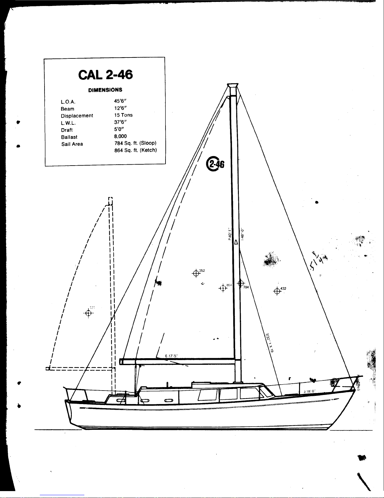
CAL 2-46
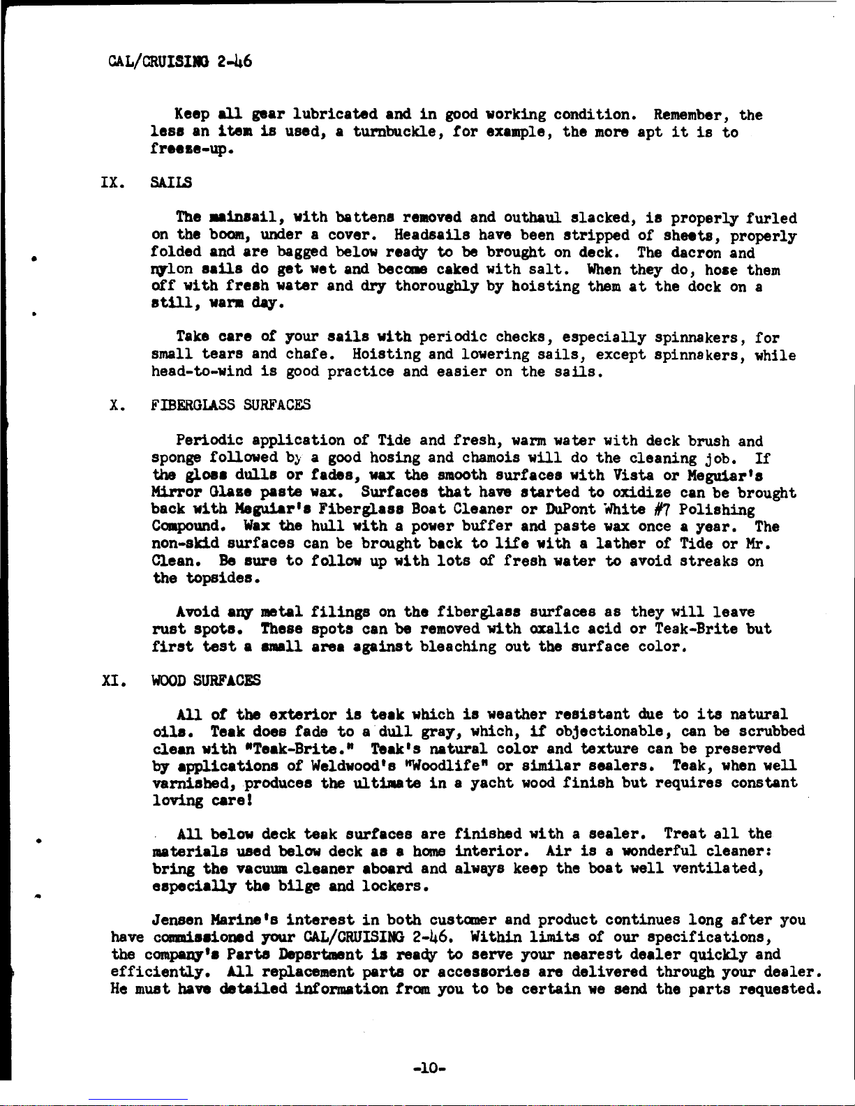
DIMENSIONS
L.O.A.
Beam
Displacement
L.W.L.
Draft
Ballast
Sail Area
/
/
/
/
/
/
I
I
'/
/
I
I
I
I
I
/
../.
'
:-"
I
·+tt-
I
I
I
I
I
I
I
I
r=====
/
/
p
,J.J
/
45'6"
12'6"
15 Tons
37'6"
5'0"
8,000
784 Sq. ft. (Sloop)
864
Sq
. ft. (Ketch)
•
".
..
•
\
..
•
CAL
2-46
•
EN
GINE
R
OOM
M
EC
HANIC
AL
AREA
~L'
I
r;;
"
"""'71
SEAT HA
TCH'
I
E
NGIN
E
AOOM
:
"'
CCESS
~
9"
LOUNGE
STOR
A
GE
UNOER
• •
I
~
.1
~~~s~'~s
I
III,
,,
0'
cd
~
I
~
& I
t-~,~')~(~.-----
t ·
:136
--
ENGINE ROOM
ACCESS
P
ASSAG
E
..
"
"NSTO
I
~
__
...
......:.
g
:...:~_~
KE
8
TE
~
;;
· 1
DRAWERS, .ICE 80 X
-------
GU
V
EJ
I~
U~
Kt~
.
e:=4.J
ENGI
NE ROOM
M
EC
IoI
AI'IIIC
AL
AREA
~
AI
L
IJ
I""
STD
rW
ORI(BEN
CM
DRA
.....
E
RS
CABIN ET
OPT.
--
....
--
t:==n:b
r-----==-=--
.
S
EAT
ST(
P
--
I
I
I
I,
Je11Se11
marine
.235
fiS
C
HER
STRHT
COSTA MESA
CALI
f
92627
BOUNDAR
Y RO
AD
MA
RL
DORO NEW
.If
RSEY
07
!
~"
@/€ /
<S
!@ 0 '
<8
'0 @
@@
crE
4b
~

•
•
•
JelIel
marile
SUBSIDIARY
OF
BANGOR PUNTA QrERATIONS. INC.
235
FISHER
STREET
/
COSTA
MESA,
CALIFORNIA
92627
~
JENSEN
MARINE
WARRANTY
Jensen
Marine
warrants
each
new
product
manufactured
by
it
to
be
free
from
defects
in
material
and workmanship under normal
use and
service
for
a
period
which
shall
expire
on
the
sooner
of
180 days
after
commissioning
by
the
original
retail
pur-
chaser,
or
one
year
after
the
date
of
shipment by
Jensen
Marine.
Jensen
Marine makes
NO
WARRANTY,
EXPRESS
OR
IMPLIED,
OF
MERCHANT-
ABILITY,
FITNESS
OR
OTHERWISE,
as
to
the
mast,
as
to
any
external
finish
applied
to
the
product
or
any
part
thereof.
Jensen
Marine makes
NO
WARRANTY,
EXPRESS
OR
IMPLIED,
OF
MERCHANT-
ABILITY,
FITNESS
OR
OTHERWISE,
as
to
engines,
toilets,
stoves,
refrigerators,
batteries,
ignition,
lighting
devices,
blowers,
propellers
(folding
or
otherwise),
and/or
other
equipment
or
trade
accessories
manufactured
by
others.
Jensen
Marine
will
deliver
to
the
original
retail
purchaser
the
warranties,
if
any,
extended
to
Jensen
Marine
by
other
manufacturers.
Jensen
Marine makes
NO
WARRANTY,
EXPRESS
OR
IMPLIED,
OF
MERCHANT-
ABILITY,
FITNESS
OR
OTHERWISE,
on
each
new
product
which
is
not
operated
or
maintained
in
accordance
with
the
Owner's Guide
fur-
nished
with
each
new
product,
or
as
to
any
product
or
part
there-
of
which has been
subjected
to
misuse,
negligent
acts
or
omissions,
or
accident.
If
within
the
foregoing
time
period
it
is
established
to
Jensen
Marine's
satisfaction
that
the
product,
or
any
part
thereof
in-
cluded
in
this
warranty,
is
defective
in
material
or
workmanship
under normal use and
service,
then
the
sole
snd
exclusive
remedy
and
Jensen
Marine's
liability
shall
be,
at
Jensen
Marine's
sole
option,
the
repairing
of
the
defective
product
or
part
thereof,
or
the
replacement
of
same
by
shipment
to
purchaser
F.o.B.
Jen-
sen
Marine's
factory
•
Defective
parts
or
products
to
be
repaired
or
replaced
pursuant
to
this
Warranty
shall
be
returned
by
the
purchaser
to
a Jensen
Marine
Dealer,
or,
if
repair
by
a
Dealer
is
determined
by
Jensen
Marine
to
be
impracticable,
returned
to
Jensen
Marine's
factory.
All
such
returns
shall
ba
freight
prepaid.
This
writing
contains
the
entire
Agreement between
Jensen
Marine
and
the
purchaser.
THERE
ARE
NO
WARRANTIES,
EXPRESS
OR
IMPLIED
OF
MERCHANTABILITY,
FITNESS
OR
OTHERWISE
WHICH
ExTEND
BEYOND
THt
FOREGOING
WARRANTY.

•
•
•
•
I.
II.
GAL/CRUISING
2-~6
INDEX
TANKAGE
.. .... ... ... . ...... . ..
Fuel
••••
Fresh Water • • ................ .. ....
SEA
COCKS
Forward Head • • • • • • • • • • • • • • • • • • • • • • • •
Engille
Room
• • • • • • • • • • • • • • • • • • • •
Aft
Head
• • • • • • • • • • • • • • • • • • • • • • • • • •
Lazerette
••
• • • • • • • • • • • • • • • • • • • • .
..
In
• P
LUMBI
l«l
IV.
ELECTRICAL
SYST»!
Battery
Condition
Indicator
••••••••••
Operation of
Circuit
Breaker
Electrical
System • ......
. .. ...
Page
1
1
1
1
1
2
2
2
2
2
3
L
V.
GALLBI
5
Mechanical
Refrigeration
and
Freezer
• • • • • • • • • • • •
••
5
VI.
HEAns
VII.
ENGINE
Vlll.
SPARS,
RIGGING
AND
HA.RIMARE
Mast
Tune
•••
• • • • • • • • • • • •
Spars
••.••.•
• • . • . • • .
Rigging
.•
• • • • • • • • • • • • • •
Hardware
. • • • • • • • • • • • • • • •
IX. SAILS
I.
FIBERGLA.SS
SURFACES
XI.
I«>OD
SURFACES
APPENDIX
·...... ...
·...........
·...........
·...........
6
7
a
8
9
9
9
10
10
10

•
•
•
OWNER'S
GUIDE
-
CAL/CRUISING
2-46
Welcome
into
the
fast-growing
owner's group of Jensen
Fiberglass
Yachts!
Your
CAL/CRUISING
2-46 has been
carefully
engineered and
built
to
require
a
minimU!Tl
of
maintenance and a
maximum
of
sailing
and powering
pleasure.
To
insure
this,
the following
is
a
description
of the
oyerational
checks and
tasks
normally
delt
with by
the
owner
to
maintain
his
CAL/CRUISING
2-46.
Each
individual
owner
should
also
be
aware
of
the
operational
and maintenance
re-
quirements of any
optional
equipment
that
has been
installed
as
that
information
may
not
be
contained
in
this
Guide •
Let's
become
acquainted
with
these
various
operations
by
preparing
a
standard
CAL/CRUISING
2-46
for
a
day's
outing and
discuss
the
maintenance
routine
which
you
should
follow.
It
is
good
practice
to
close
the
fuel
shut-off
valves
and
all
sea
cocks
when
leaving
your
boat,
especially
for
extended
periods
of
time.
The
"coming
on
board" and the opening of
these
fittings
starts
our
"Sailing
Check-off
List.
"
I.
TANKAGE
A.
FUEL
II.
The
two
135
gallon
10 gauge
steel
DIESEL
FUEL
TANKS
are
located
under the
main cabin
sole
with
their
tank
fills
on
~eck,
port
and
starboard,
and
their
vents
directly
above
on
the cabin
side.
The
Fuel
Shut-off
Valves
are
on
the
forward engine
room
bulkhead along
with
their
respective
capacity
gaui8s.
When
not
operating
the
engine,
these
valves should remain
CLOSED.
B.
FRESH
WATER
Two
85
gallon
stainless
steel
Fresh
Water Tanks
are
also
located
under the
main cabin
sole
with
their
tank
fills
and
vents
adjacent
to
the
fuel
tanks.
The
valves
for
these
tanks
are
in
a compartment
on
the forward engine
room
bulkhead along with
their
respective
capacity
gauges.
If
the
optional
50
gallon
fresh
water tanks have been mounted, they
will
be forward of
the
diesel
fuel
tanks
but
their
valves
will
also
be
here.
SEA
COCKS
'tJ.'.;,£
..
t.
All
below water
line
through
hull
fittings,
except
the
optional
speed
indicator,
are
equipped with bronze
.....
Avalves.
When
the
optional
equipment
is
added,
there
could
be
a
total
of
9,
so
it
is
vital
that
you
know
the
location
of
these
valves.
Gate
valves
OPEN
by
turning
COUNTER-CLOCKWISE
and
CLOSE
in
a
CLOCKWISE
direction.
It
is
a
good
idea
when
you open any
gate valve
to
then
close
it
a
quarter
turn.
In
this
way,
anyone can im-
mediately
tell
if
a valve
is
open
or
not.
Open
valves
are
sometimes broken
by
someone
tr,ying
to
pr.y
them
further
open,
thinking
they
are
closed.
FollOWing
is
the
location
and
function
of
the
9 gate
valves.
A.
FORWARD
HEAD,
4
valves
All
of
these
valves
are
located
in
the
locker
directly
under the lavator.y
with
the
follOWing
functions:
-1-
F
•
•
CAL/CRUISING
2-46
1.
1
1/4"
valve
for
Marine
Toilet
Discharge -
2.
3/4"
valve
for
Lavatory
and
Galley Sink
Drain]
3.
1/2:
~alve
forMar~ne
Toile~
Water Intake
4.
l/~
16va.~
Wa~p
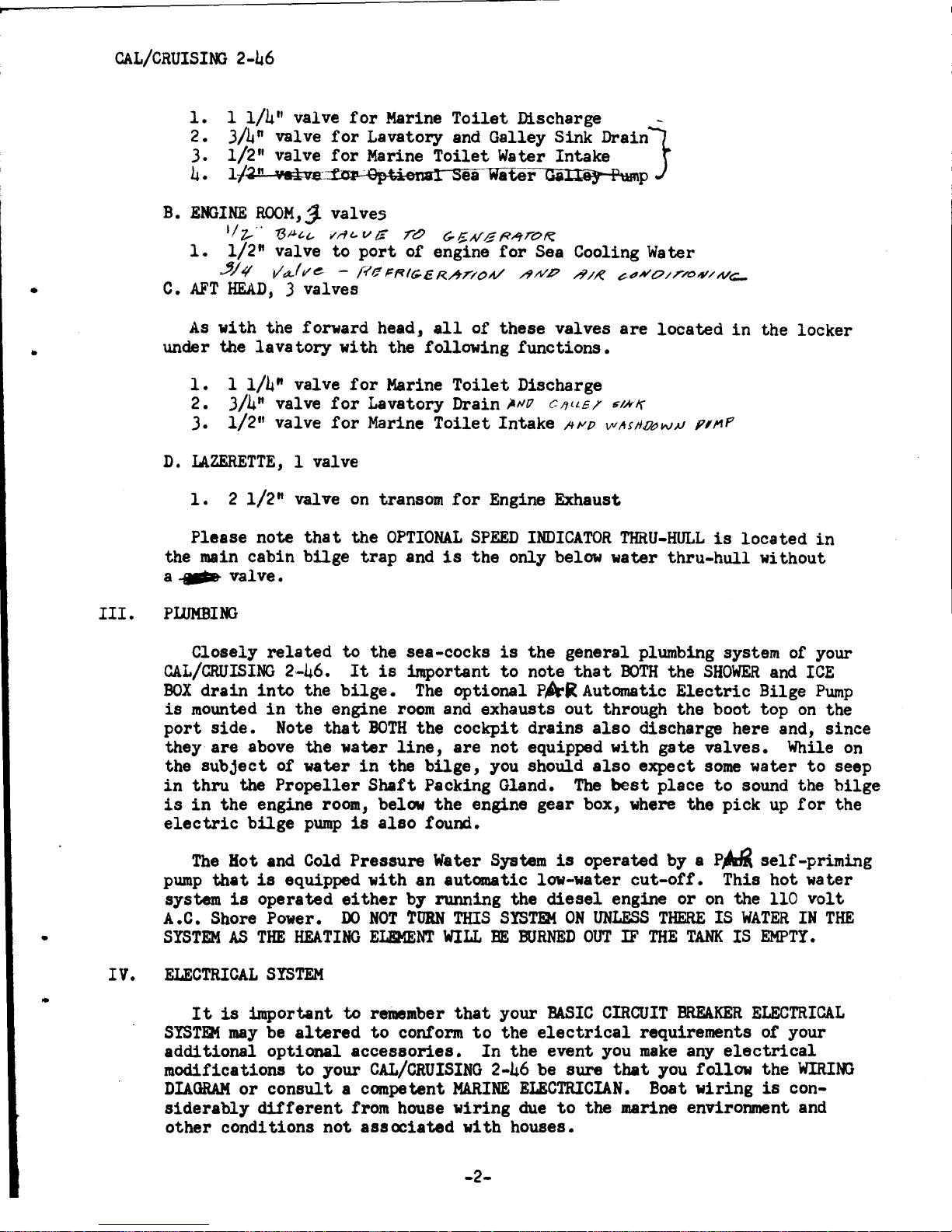
B.
ENGINE
ROOM,
j.
val
ve5
1/
z.."
13#(.("
;tnt.. v IS
reJ
(;.~A/G
R~rOIi:
1.
1/2"
valve
to
port
of engine
for
Sea Cooling Water
~J4
vr;k'/j/e
-
l;re~F?Ic;.ERA""I'()A/
/PHP
/Y//f
?t?N'O/T/O;Y/If/<:;..
C.
AFT
HEAD,
3 valves
As
with the forward head,
all
of
these
valves
are
located
in
the
locker
under the
lava
tory
with the following functions •
1.
1
1/4"
valve
for
Marine
Toilet
Discharge
2.
3/4"
valve
for
Lavatory Drain )."'17
C-lfllEI'
r;/NI)
3.
1/2
11
valve
for
Marine
Toilet
Intake
If""!)
vvltSlf!»WN
p",P
D.
LAZERETTE,
1 valve
1.
2
1/2"
valve
on
transom
for
Engine Exhaust
Please
note
that
the
OPTIONAL
SPEED
INDICATOR
THRU-HULL
is
located
in
the main cabin
bilge
trap
and
is
the
only below water
thru-hull
without
a
~
valve.
III.
PWMBING
Closely
related
to
the sea-cocks
is
the
general plumbing system of your
CAL/CRUISING
2-46.
It
is
important
to
note
that
BOTH
the
SHOWER
and
ICE
BOX
drain
into
the
bilge.
The
optional
pA-R
Automatic
Electric
Bilge
Pump
is
mounted
in
the
engine
room
and exhausts
out
through
the
boot top
on
the
port
side.
Note
that
BOTH
the
cockpit
drains
also
discharge here and,
since
they
are
above the water
line,
are
not
equipped with gate
valves.
While
on
the
subject
of water
in
the
bilge,
you
should
also
expect
some
water
to
seep
in
thru
the
Propeller
Shaft
Packing Gland.
The
best
place
to
sound the
bilge
is
in
the
engine room, below
the
engine gear box,
where
the
pick
up
for
the
electric
bUge
pump
is
also
found.
The
Hot and Cold Pressure Water System
is
operated by a
P~
self-priming
pump
that
is
equipped
with
an automatic low-water
cut-off.
This
hot
water
system
is
operated
either
by running the
diesel
engine
or
on
the
110
volt
A.C. Shore Power.
DO
NOT
TURN
THIS
SYSTm4:
ON
UNLESS
THERE
IS
WATER
IN
THE
•
SYSTEM
AS
THE
HEATING
ELEMENT
WILL
BE
BURNED
OUT
IF
THE
TANK
IS
EMPTY.
..
I V•
ELECTRICAL
SYSTEM
I t
is
important
to
remember
that
your
BASIC
CIRCUIT
BREAKER
ELECTRICAL
SYSTEM
may
be
altered
to
conform
to
the
electrical
requirements of your
additional
optional
accessories.
In
the
event you
make
any
electrical
modifications
to
your
CAL/CRUISING
2-46 be sure
that
you follow the
WIRING
DIAGRAM
or
consult
a competent
MARINE
ELECTRICIAN.
Boat
wiring
is
con-
siderably
different
from house wiring
due
to
the marine environment and
other
conditions
not
associated
with houses.
-2-

•
•
•
GAL/CRUISING
2-46
The
Master
Power
Control Panel
features
integrated,
simplified
controls
and
circuit
breaker
protection
to
permit
safe
and
efficient
operation
of
your
boat's
electrical
equipment.
All
panel components have been
carefully
selected
for
their
proven performance
in
marine
applications.
The
baSic
panel
is
of
a metal
alloy
which
is
inherently
corrosion
resistant
and
is
doubly
protected
to
optimize
resistance
to
the
effects
of
the
marine
envir-
onment. A
one
year
warranty
will
be
validated
by Marinetics Corporation,
P.O.
Box
1015, Newport Beach,
Calif.
92663,
if
the enclosed warranty
re-
gistration
form
is
submitted
within
30
days from the date of commissioning•
~/I.
()
It
1'1(-
~1Z
1JArV1:.5
Electrical
current
is
directed
from
two
12
volt,
~
batter~ythrough
the Master
Power
Control Panel
for
engine
starting,
battery
charging, and
accessory
loads.
Since the
GAL/CRUISING
2-46
is
designed
to
do
considerable
cruising
and
"living
aboard" an
optional
208
amp
battery
may
be added
to
meet
these
additional
electrical
requirements. Panel
selection
of
"BAT
1" or
"BAT
2"
determines which of the
two
battery
sets
will
be
utilized
for
engine
starting
and subsequent charging. Before
activating
the
electrical
system,
use the
Battery
Condition
Indicator
to
ascertain
the condition of your
batteries.
A.
BATl'ERY
CONDITION
INDICATOR
This type of
"indicator"
or
"meter"
is
technically
referred
to
as
a
"Suppressed Zero Voltmeter".
Note
that
calibrations
do
not
start
at
zero
but
provide a
full
scale
reading from 8
to
10
or
16
volts,
depending
on
the
meter.
Below
8
to
10
volts
the
battery
charge
is
so
low
that
terminal
voltage readings
are
meaningless. Approximate voltage range
interpretations
are
as
follows:
Engine
Not
Running
or
at
Idle
Engine
Running
Above
Idle
)
)
)
Below
II
- - - - - - Very
low
battery
charge
11 -12 ------
Low
battery
charge
12
-13 - - - - - - Well charged
battery
------------------ - ------
)
)
)
13
to
13* -----
Low
charge
rate
131
to
l5t
- - - - -
Alternator
&Voltage Regulator
OK
15i
or above - - - - Voltage Regulator out of Adjustment
It
is
iaportant
for
you
to
understand
that
the reading
on
the
Battery
Condition
Indicator
Dial
is
indexed from the
TOGGLE
TEST
SWITCH
POSITION
REGlRDLISS
OF
THE
MASTER
SWITCH
POSITION
unless
it
is
in
the
"BOTH"
position
•
When
the Master Switch
is
in
the
"BOTH"
position
then the
Battery
Condition
Indicator
Dial
wUl
indicate
BOTH
BATTERY
CONDITIONS
NO
MATTER
WHICH
WAY
THE
TOGGLE
TEST
SWITCH
IS
INDEXED.
When
the
Master Switch
is
in
either
the
"OFF",
"BAT
1"
or
"BAT
2" pOSitions, the
_ter
will
read the
condition
of
the
battery
TCJWA.RnS
which you index the Toggle
Test
Switch.
Note
that
panel
and meter
illumination
is
also
provided
bY'
this
same
Toggle
Test
Switch.
Before
activating
the
electrical
,sY'stem,
check the
condition
of
both
battery
sets
and then
select
the
STROl«lEST
BATTERY
FOR
ENGINE
STARTING.
-3-
•
•
•
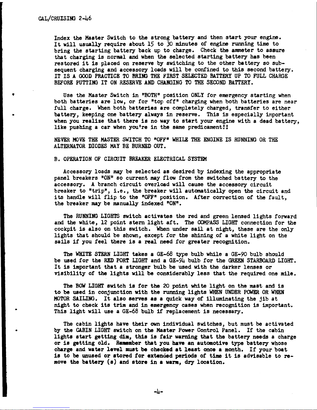
CAL/CRUISING
2-46
Index
the
Master
Switch
to
the
strong
battery
and
then
start
your
engine.
It
will
usually
require
about
15
to
)0
minutes
of
engine
running
time
to
bring
the
starting
battery
back
up
to
charge.
Check
the
anuneter
to
assure
that
charging
is
normal and when
the
selected
starting
battery
has been
restored
it
is
placed
on
reserve
by
switching
to
the
other
battery
so
sub-
sequent
charging
and
accessory
loads
will
be
confined
to
this
second
battery.
IT
IS
A
GOOD
PRACTICE
TO
BRIt«}
THE
FIRST
SELECTED
BATTERY
UP
TO
FULL
CHARGE
BEFORE
PUTTING
IT
ON
RESERVE
AND
CHANGING
TO
THE
SECOND
BATTERY.
Use
the
Master
Switch
in
"BOTH"
position
ONLY
for
emergency
starting
when
both
batteries
are
low,
or
for
"top
off"
charging
when
both
batteries
are
near
full
charge.
When
both
batteries
are
canpletely
charged,
transfer
to
either
battery,
keeping
one
battery
always
in
reserve.
This
is
especially
important
when
you
realize
that
there
is
no
way
to
start
your
engine
with
a dead
battery,
like
pushing
a
car
when
you're
in
the
same
predicament!!
NEVER
MOVE
THE
MASTER
SWITCH
TO
"OFF"
WHILE
THE
ENGINE
IS
RUNNING
OR
THE
ALTERNATOR
DIODES
MAY
BE
BURNED
OUT.
B.
OPERATION
OF
CIRCUIT
BREAKER
ELECTRICAL
SYSTEM
Accessory
loads
may
be
selected
as
desired
by
indexing
the
appropriate
panel
breakers
"ON"
so
current
may
flow
from
the
switched
battery
to
the
accessory.
A
branch
circuit
overload
will
cause
the
accessory
circuit
breaker
to
"trip",
i.e.,
the
breaker
will
autanatically
open
the
circuit
and
its
handle
will
flip
to
the
"OFF"
position.
After
correction
of
the
fault,
the
breaker
may
be manually
indexed
"ON".
The
RUNNING
LIGHTS
switch
activates
the
red
and
green
lensed
lights
forward
and
the
white,
12
point
stern
light
aft.
The
COMPASS
LIGHT
connection
for
the
cockpit
is
also
on
this
switch.
When
under
sail
at
night,
these
are
the
only
lights
that
should
be shown,
except
for
the
shining.of
a
white
light
on
the
sails
if
you
feel
there
is
a
real
need
for
greater
recognition.
The
WHITE
STERN
LIGHT
takes
a
GE-68
type
bulb
while
a
GE-90
bulb
should
be used
for
the
RED
PORT
LIGHT
and a
GE-94
bulb
for
the
GREEN
STARBOARD
LIGHT.
It
is
important
that
a
stronger
bulb
be
used
with
the
darker
lenses
or
visibility
of
the
lights
will
be
considerably
less
that
the
required
one
mile.
The
BOW
LIGHT
sn
tch
is
for
the
20
point
whi
te
light
on
the
mast and
is
to
be
used
in
cOnjunction
with
the
running
lights
WHEN
UNDER
POWER
OR
WHEN
MOTOR
SAILING.
It
also
serves
as
a
quick
way
of
illuminating
the
jib
at
night
to
check
its
trim
and
in
emergency
cases
when
recognition
is
important.
This
light
will
use
a
GE-68
bulb
if
replacement
is
necessary
•
The
cabin
lights
have
their
own
individual
switches,
but
must
be
activated
by
the
CABIN
LIGHT
switch
on
the
Master Power
Control
Panel.
If
the
cabin
lights
start
getting
dia,
this
is
fair
warning
that
the
battery
needs
a
charge
or
is
getting
old.
Be_.ber
that
you
have
an
automotive
type
battery
whose
charge
and
water
level
IllU8t
be
checked
at
least
once a month.
If
your
boat
is
to
be
unused
or
stored
for
extended
periods
of
time
it
is
advisable
to
re-
move
the
batterr
(s)
and
store
in
a
varll,
dry
location.
-4-

CAL/CRUISlIG
2-46
Periodically
check
all
wires,
connections,
and
terminals
for
loose
connections
which mAl cause
electric
sparks
or
power
loss.
This
is
es-
pecially
11Iportant
with
the
engine
wires.
When
leaving
the
boa
t,
FIRST
TURN
OFF
THE
DOIHE,
THEN
INDEX
THI
MASTER
SWITCH
TO
OFF.
v.
cw.LII
The
Water
S1St.
and
Sink
Drain
haft
been
covered
earlier.
Mention
was
a180
_de
tbJIt
the
100 pound
Ice
Box
drains
into
the
bilge.
Ope:sMiug-
'"
inatnletione-lw-the-
optioad--3--bumer-·
Preanre
.....
lcobol·
StOfe"COM""""1ftt1f
the
atove
'nit
a
tn
addj
tioul
.pe1ftta-are--important.
•
2
sallon
Presaure
Tank
is
in
the
locker
just
forward
of
the
stove.
When
lling
this
tank,
please
observe
the
following
BEFORE
removing
the
stopper:
"'-,
1.
All
bu~s
are
OFF
..,r/'
·
2.
Main
IlCO~-oft
""lve
on
top
of
pre~~'9"~;
/
1a
CLOSED.
3.
Tank
pressure
is
ZD(h
Remove
Sto~:/
,
/~
~
4.
Fill
the
tank
three-qua~~
'
l'~l
to
allow
for
air
pressure.
"
"'-
5. Replace
stopper
,..!._.'8~
d~t.
6.
IxperieDC~ShOWn
that
5
pounds"'o~tank
pressure
is
more
than
ad~,ati
and imposes
less
strain
on
the
ittings
than
the
re-
~nded
10 pounds.
Following
is
a
description
of
the
optional
mechanical
installed
bJ
the
factory.
MECIWlICAL
REFRIGERATION
j.HI)
FREEZER
(Mechanicold)
rigeration
system
,/
/
~
Chan1Cal
refrigeration
and
freezer
in
this
applica
on
is
defined
a.
a
run
ott
tbe
engine.
The
teaperature
is
re
d manually,
but
there
a
tMraoatat
to
prevent
the
refrigerator
CIIl
becoming
too
cold.
When
ei
tber
~friaerator
or
freezer
becOl18
va
the
engine
is
started
aDd
the
878tea
nitclled
on
and
run
until
tbe
fre
r
becCllles
cold.
The
run-
n1Dc
tiM
w111
va1'7,
~nd1nl
on
how
long
t
ra
ture
is
maintained
in
the
freezer.
'- ,
"',
" "
The
qetea
18
composed
of
the
1"0_
....
___
components, which
are
also
alphabetically
indexed
in
the
dia~<~~Appendix.
~
..
A.
The
cGlllpreaaor
is
a two
C7
der
auta.oti
v.'1i.!"
conditioning
type,
mounted
on
the
engine.
The c
ssor
pulle7
has
a 12 t
electric
clutch
and
is
clri
ftn
by
tvo
V be
otf
all
auxillary
pulley
on e
engine.
Belt
tension
is
recuJ,a
by
adjueting
the
co.pressor
or
adj
an
idler
pulley.
B. The condenae s plUllbeci
into
the
engine raw
water
cooling
Systell
b8fore
the
vater
tars
the
enline
(or
the
beat
exchanpr
in
the
CBse
of
a
fresh
water
c
ad
engine).
/'
-5-

•
•
..
•
ClL/CRU1SINl 2-46
VI.
c~\
The
Rec.iTer
incorporates
a
built-in
drier
and a
sight
glass
to
permit
~hecldng
the
amount
of
refrigerant.
/
D.
T~ExpaDs10n
Valves
control
the
flow
of
refrigerant
into
t E....
porators.
E.
The
E~porator
consists
of
tubing
coils
in
an
eutetic
so
·001.1-
'~old
plates.
F.
The
Therm~-ters
are
mounted
in
a
position
so
they
n
be
easily
observed
and
the
;l:;;nt
bulb
in
the
box
is
about
mid-heigh •
\
G. A Switch
to
cdrltrol
the
electric
clutch
may
inc
orate
a
red
light
to
show
when
the
switch
is
on.
/
H. A High
Pressure
'~ut-off
switch
is
provided
'disconnect
the
electric
clutch
if
the
system
pressure
becomes
too~igh,
usually
due
to
lack
of
cooling
water.
/
Conventional
refrigera~on.
tubing
and
~ttingS
are
used
with
refrigerant
hose between
the
compressor\and
the
re~l~f
the
system
to
absorb
vibration.
, /
The
operation
of
the
Syste~\d
tJx'
function
of
the
components
is
as
follows:
/
,
The
refrigerant
is
piped
~o
t
e~xpansion
valves
(D) from
the
receiver
(C)
as
a
liquid
and
the
amount
of
ow
i~
regulated
by
the
telllperature
of
its
thermal
bulb
(F)
attached
to
e
outl~t
line
of
the
evaporators.
In
the
evaporators
(I),
the
refrige,
nt
picks\up
heat
and
is
changed
to
a
gas.
The
gas
is
piped
to
the
compres~or
(A)
wher~
it
is
changed from a gas
at
low
pressure
to
a gas at
high
"pressure.
Thi~
high
pressure
gas
is
piped
to
a
condenser (B) where
the
peat
is
'taken
out
~
the
engine raw
water.
This
changes
the
gas
to~
ai
uid
which
is
piped
~
the
receiver
(C) and
the
cycle
continues.
No
ad.jus
nts
are
required,
simpq
run
the
compressor (A) long
enough
to
maintain
e
desired
temperature.
'\
I
~
/ "
The
High
Press~e
cut-off
awi
tch
(H)
is
an
exc~ent
safety
device,
as
it
prevents
damage
~QIl
excessive
pressure
due
to
lack'\¢'
cooling
water.
This
can be
the
re~t
of
a clogged
inlet
line,
the
thru
~l
water
intake
valve
accidently
lett
closed,
or
being
heeled
over
far
enou~
for
the
water
intake
thru-hull
to
be
out
of
the
water.
\
\
The
reftigerator
temperature
control
can be
adjusted
th
prevent
too
low a
temperature
in
the
box, which would
freeze
Ililk,
vegetables,
beer,
etc.
The
Freezer
/can
be
run
as
long
as
desired
wi
thout
ill
effects.
~is
provides
an
I
.~
exceUent
way
of
_king
ice
cubes.
',.
j .
.ad1tional
information
and
replacement
parts
must
be
obtained
ts:om
the
or,tg1nal
manufacturer:
Boat
SpeCialists,
Inc.,
2439
West Coast Highway,
lf6wport Beach, Ca. 92660. Phone 114/645-0901.
HEADS
Complete
operating
instructions
for
the
Marine
Toilets
are
on
metal
plates
wbich
may
be
mounted where
desired.
These
plates
along
with
additional
in-
structions
and
parts
lists,
bave
been
included.
-6-.

•
•
•
CA.L/CRUISIIIl
2-46
OON'
T
FORGET
THE
EARLIER
TANKAGE
AND
SEA
COCK
INSTRUCTIONS.
VII.
ENGINE
Operating
procedure8
are
well
covered
in
the
enclosed
manual, however
several
important
pOints
should
bere-emphasized:
A.
Turn
the
Main
Battery
Switch,
located
on
the
Master Power
Control
Panel,
to
the
position
you have
de8ignated
'
as
tile engine
battery.
When
the
engine
is
IDLING
you
may
switch
from
one
b~ttery
position
to
the
other
for
ch~rging
•
NiVER
paS8
through
the
"OFF"
position
or
the
Alternator
Diodes
will
be burned
out.
The
"BOTH"
position
is
used
to
start
the
engine
when
both
batteries
are
low.
When
the
engine
is
not
running,
use one
of
the
batteries
for
ship's
gear,
thus
saving
the
second one
for
starting
the
engine.
B.
Prior
to
starting
the
engine,
please
check
the
following:
1.
The
engine
is
fresh
water
cooled
through a
salt
water
heat
exchanger.
It
is
extremely
1JIportant
that
the
fresh
water
header
tank
be
full
to
within
an
inch
of
the
top
and
the
cap
on
tight.
.
For
technical
reasons,
the
choice
of
lubricating
oil
is
more
important
in
a
Diesel
than
in
a
gasoline
engine.
Check
the
dip
stick
on
the
engine's
port
side.
The
oil
must be
drained
every
50 hours and
re-
placed
with
5
quarts
of
a "H.D."
detergent
oil.
Also
change
the
filter
at
this
t:ille.
"RPM
DELO
Multi-5ervice
SAE-30"
is
used
at
the
factory,
but
other
approved
oils
are
listed
on Page
37
of
the
manual.
The
transmission
bas
one
quart
of
"Chevron Automatic Transmission
fluid-
which
should
be
changed
after
the
fir8t
50
operating
hours and
evel'1 500 hour8
thereafter.
C.
Place
Shift
lever,
port
side
of
Control
Unit
in
NEUTRAL
or
the
vertical
position.
D.
Pull
out
1natrument knob
to
activate
in8truments.
E. Water and
Fuel
ON?
Exhaust Valve
OPEN?
F.
Push
Starter
Button.
When
engine
starts:
1.
Adjust
Throttle,
starboard
lever
on
Control
Unit,
to
Idling
Speed
of
700
RPM.
2.
Check 011
pres8ure
-
40
pounds•
3.
Cooling system
is
operating
only
if
water
i8
coming
out
of
Exhaust
Outlet
in
transOJll. Engine
operating
temperature
is
1700,
•
4.
If
water
doe8
not
begin
to
flow
out
of
the
transom
outlet
within
3
or
4
minute8,
STOP
the
engine and check
water
intake
and exhaUlit
gate
valves.
5.
If
oU
pre8Bure
i8
low,
STOP
the
engine and check
oil
level.
-7-

•
•
•
•
CA.L/CRUISIIG
2-46
6.
The
Propeller
Shaft
Packing Gland,
located
under
the
AFT
Cabin
Sole,
should
be
damp.
Tighten
the
nuts
snug enough
to
eliminate
aq,y
excess
water
drips.
Q.
Run
engine
at
idle
when
shifting
into
forward
or
reverse.
At 2100
RPM
the
atL/CRUISING
2-46
will
power around 8.2
knots
using
about
1.7
gallons
of
fuel
per
hour.
In
smooth
water,
higher
speeds can be
obtained
with
higher
RPM's
but
fuel
consumption
will
increase
accordingly.
B.
To
Shut
Down
Engine:
1.
Pull
"KILL"
Knob
in
instrument
panel.
2.
Push
in
Instrument
Knob.
3. Close
Fuel
Valves and
Gate
Valves.
I.
There
are
only
two main
reasons
a
Diesel
engine
will
stop
running.
One,
when
the
engine
has
run
out
of
fuel
or
there
is
an
air
bubble
in
the
fuel
line
j and two,
if
the
engine
bas overhea
ted
caUSing
the
engine
to
"freeze".
If
the
water
level
is
OK,
and
there
is
sufficient
fuel
(and
fuel
shut-off
valves
are
open)
the
fuel
system
will
have
to
be
"bled".
This
can
be
done
without
the
assistance
of
a mechanic and
is
explained
in
the
Appendix.
With
the
engine
running,
your
CAL/CRUISING
2-46
is
ready
to
get
underway.
We
should
pause
for
a
moment
and
look
about
the
deck
thus
becoming
acquainted
with
the
sailing
gear.
VIII.
SPARS,
RIGGIW
AHD
HARDWARE
It
is
!.possible
to
fully
guaran~e
the
mast
of
your
CAL/CRUISING
2-u6
under our
current
warranty
program. Rigging
as
well
as
tuning
becomes
all
iaportant
when
setting
up
the
mast because
of
the
light
weight
section
we
use.
J.
knowledgeable
person
should
oversee
the
rigging
and
tuning
so
as
to
eliminate
the
possibility
of
an
eccentric
load
which might
occur
with
an
improperly
loaded
shroud.
Special
attention
should
be
given
to
the
initial
stretch
of
the
uppers and a
further
gradual
stretch
of
the
wire
over
the
first
few
hard
8ails.
A.
MAST
ruNE
The
JJa8t
should
be
set
straight
athwart-ships
in
the
boat
and have a
slight
rake
aft.
A
straight
mast can
best
be
obtained
by
turnbuckle
adjustment
while
sailing
to
windward
in
a ,
to
10
mph
breeze.
The
head
of
the
mast
should
NOT
"hook"
to
windward.
If
not
straight,
it
would
be
more
desirable
to
have
the
head
"fall-otf"
slightly
to
leeward.
This
should
give
the
mast a smooth,
even
curft
froll
head
to
deck.
Sighting
along
the
back
of
the
mast
on
each
tack,
from deck
level,
will
give
a
canparlson
and
indicate
the
necessary
ad-
jusi'.-nta.
For
noraal
cruising
conditions,
we
recOllJll8nd
a
"firm"
rig.
Thus a dock-
side
starting
point
would have
the
heads
tal'
,
backatay,
Jdd-stay
and uppers
tight,
the
inter.diates
not
so
tight
and
lovers
fairly
firm.
low
the
back-.
stay
..
y
be
_de
slightly
tighter
to
"hook"
the
top
of
the
mast
aft.
One

•
•
•
..
CAL/CRUISING
2-46
should
be
able
to
stand
facing
the
mast,
reach
out
and
pull
on any
stay
and
see
the
mast
move
in
that
direction.
Try
to
get
tension
on
both
stays
equal
with
about
1/2"
to
2"
of
play
on
the
uppers,
2"
to
3"
on
the
lowers
and
about
2-
on
the
intermediates.
The
intennediates
are
set
last
and
serve
to
balance
the
pull
of
the
uppers
and
lowers.
A
dascription
of
all
standing
and
running
rigging,
if
replacement
is
neceseary,
can
be
found
in
the
Appendix. FollOWing
are
sane maintenance
tips
which
should
be
of
value
•
B.
SPARS
The
finish
of
natural
aluminum
is
protected
against
corrosion
by a
thin,
transparent
film
of
aluminum
oxide.
Dust,
dirt,
smoke,
salt
and
traffic
fumes
will
adhere
to
this
film,
making
the
surface
dull
and
unsightly.
Coating
the
new
surfaces
with
a good
paste
wax
like
Vista
or
Simonize,
will
help
protect
the
aluminum
oxide
from
foreign
matter.
If
the
surface
has
become
tarnished,
any
high
grade
cleaner
-
wax
-
polish
(Collinite
#34
or
#38
for
example)
will
restore
the
original
sheen.
Heavier
pitting
can be
removed by
wet-sanding
with
IIfIJO
paper
prior
to
polishing
and waxing.
You
need
not
worry
about
sanding,
cleaning
or
polishing
destroying
the
aluminum
oxide
fUm
as
it
reforms
or
-beals"
immediately.
If
spars
are
black
anodized,
hose
down
portions
subject
to
salt
water
spray
after
each
sail.
~L.VMINVh
The
spreaders
are
of
apNea
and
haft
'heft
"a.de o
Blitbhed.
Beee1Hle
ef
84
1)
ahafe
and
weather,
they ah8lllEi
l!Ie
la_eEl
and
l'e-v.udshed
e,e17
"8ix
months and
the
UpS
re
taped.
C.
RIGGING
Clean
rigging
means
clean
saUs.
A
quick
trip
aloft
with
damp
rags
takes
care
of
this
problem. While
aloft,
check
the
entire
rig
for
loose
screws,
nuts,
bolta,
cotter
pins
and
chafe
which
may
have
resulted
from
hard
sailing.
Periodic
inspection
of
the
rig
from
aloft
is
your
best
insurance
against
rigging
and
spar
failure.
Keeping
halyards
tied
away
fran
the
mast
stops
the
annoying
dockside
clanldng
and
saves
the
mast
finish.
Salt
water
will
gradually
stiffen
dacron
line.
HOSing
with
fresh
water
or
soaking
in
warm
soapy
water
will
make
the
line
soft
and
flexible
again.
Keep
coiled
and stowed
in
a
dry
spot
below•
D.
HARIWARE
Many
materials
are
used,
all
of
which
clean
well
with
fresh
water
and a
chamois. Winches must be
kept
clean
and
well
oiled
(Lubriplate
is
excellent
unless
the
manufacturer
rec~nds
otherwise)
as
do
all
turnbuckles,
track
slides,
sbeaves
and
shackles.
The
cbrolll and
stainless
steel
brighten
up
with
the
chamois
while
a
good
automotive chrome
cleaner
or
mild
kitchen
abrasive
like
Comet
takes
care
of
the
tarnished
spots.
-9-
•
•
•
'"
CAL/CRUISIJI)
2-46
IX.
Keep
all
gear
lubricated
and
in
good working
condition.
Remember,
the
less
an
ite.
is
used,
a
turnbuckle,
for
example,
the
more
apt
it
is
to
fr
•••
e-up.
The
_insail,
with
battens
rellOved and
outhaul
slacked,
is
properly
furled
on
the
boom,
under a
cover.
Headsails
have been
stripped
of
sheets,
properly
folded
and
are
bagged below
ready
to
be
brought
on deck.
The
dacron and
~lon
sails
do
get
wet and
beCQ18
caked
with
salt.
When
they
do, hose them
orf
with
fresh
water
and dr,y
thoroughly
by
hoisting
them
at
the
dock
on
a
stUl,
wara
day
•
Take
care
of
your
sails
with
periodic
checks,
especially
spinnakers,
for
small
tears
and
chafe.
Hoisting
and
lowering
sails,
except
spinnakers,
while
head-to-wind
is
good
practice
and
easier
on
the
sails.
X.
FIBERGLASS
SURFACES
Periodic
application
of
Tide and
fresh,
warm
water
with
deck
brush
and
sponge
followed
b;y
a good
hosing
and chamois
will
do
the
cleaning
job.
If
the
glos.
dulls
or
fades,
wax
the
smooth
surfaces
with
Vista
or
Megu1ar's
Mirror
Glase
paste
wax.
Surfaces
that
have
started
to
oxidize
can
be
brought
back
with
Maguiar's
Fiberglass
Boat
Cleaner
or
DuPont White
N7
Polishing
CoapolUld.
Wax
the
hull
with
a power
burfer
and
paste
wax
once a
year.
The
non-skid
surfaces
can be
brought
back
to
life
with
a
lather
of
Tide
or
Mr.
Clean.
Be
sure
to
follow
up
with
lots
of'
fresh
water
to
avoid
streaks
on
the
topsides.
Avoid anT
metal
filings
on
the
fiberglass
surfaces
as
they
will
leave
rust
spots.
These
spots
can
be removed
with
oxalic
acid
or
Teak-Brite
but
first
test
a
amall
area
against
bleaching
out
the
surface
color.
XI.
WOOD
SURFACES
All
of
the
exterior
is
teak
which
is
weather
resistant
due
to
its
natural
oils.
Teak does
fade
to
a·
dull
gray,
which,
it
objectionable,
can be scrubbed
clean
with
"Teak-Brite."
Teak's
natural
color
and
texture
can
be
preserved
by
applications
of
Weldwood's "Woodlife"
or
similar
sealers.
Teak,
when
well
varn1shed,produces
the
ult1.Jll8te
in
a
yacht
wood
finish
but
requires
constant
loving
care!
All
below deck
teak
surtaces
are
finished
with
a
sealer.
Treat
all
the
I18tarials
used
below deck
as
a
home
interior.
Air
is
a wonderful
cleaner:
bring
the
vacuum
cleaner
aboard and always keep
the
boat
well
ventilated,
especiall7
the
bUge
and
lockers.
Jensen
Marine's
interest
in
both
custClD.8r
and
product
continues
long
after
you
have cOllllis.ioned 1'O'lr
CAL/CRUISING
2-46.
Within
limits
of
our
speCifications,
the
cOl1lpaDT'.
Parte
Depsrtment
is
ready
to
serve
your
nearest
dealer
quickly
and
efficiently.
All
replaceJllent
parts
or
accessories
are
delivered
through
your
dealer.
He
must have
detailed
information
trom you
to
be
certain
we
send
the
parts
requested.
-10-

•
•
•
..
CAL/CRUISING
2-46
Addi
tional
sailing
and
maintenance
tips
can
be
found
in
various
boating
publicationa.
Yachting'
a Annual Maintenance
Issue
in
April
is
an
excellent
starting
pOint.
This
brings
us
to
the
end
of
our
"Sailing
Check-List"
and
leaves
only
the
securing
of
your
CAL/CRUISING
2-46.
If
we
ran
the
list
in
reverse,
adding
only
one
item,
your
CAL/CRUISING
2-46
will
be
ready
for
the
next
sail.
This
one
important
item
is
a
GOOD
HOSING.
Nothing keeps a
boat
better
than
fresh
water
and
the
chamois.
Use
plenty
of
pressure,
espe
cially
in
the
cockpit
scuppers.
non-skid
areas
and
metal
surfaces.
Turn
to
with
sponge and chamois and you
will
be
rewarded
with
a
sharp,
sparkling
yacht
that
is
only
matched
by
its
comparable
performance
•
Good
Luck and Happy
Sailing
JENSEN
MARINE
-11-
•
•
•
STAR11NG
TIlE
ENGINE-D.
I
STARTING THE ENGINE
(D)
Preparadon for
StartInc.
Check the header tank water level when fitted.
Check the engine sump oil level.
See that there
is
fuel oil in the tank.
Check that the starter battery
is
fully charged
and that all electrical connections are properly
made and all circuits are in order.
Check that
sea
cock
is
open. when fitted.
Lubrka
....
00.
During the normal winter period, a lubricating
oil of S.A.E.
lOW
viscosity of high detergency
conforming to MIL/L/2104A
or
OEF/210~B
specification should
be
used.
For
approved
Oils.
see
appendix.
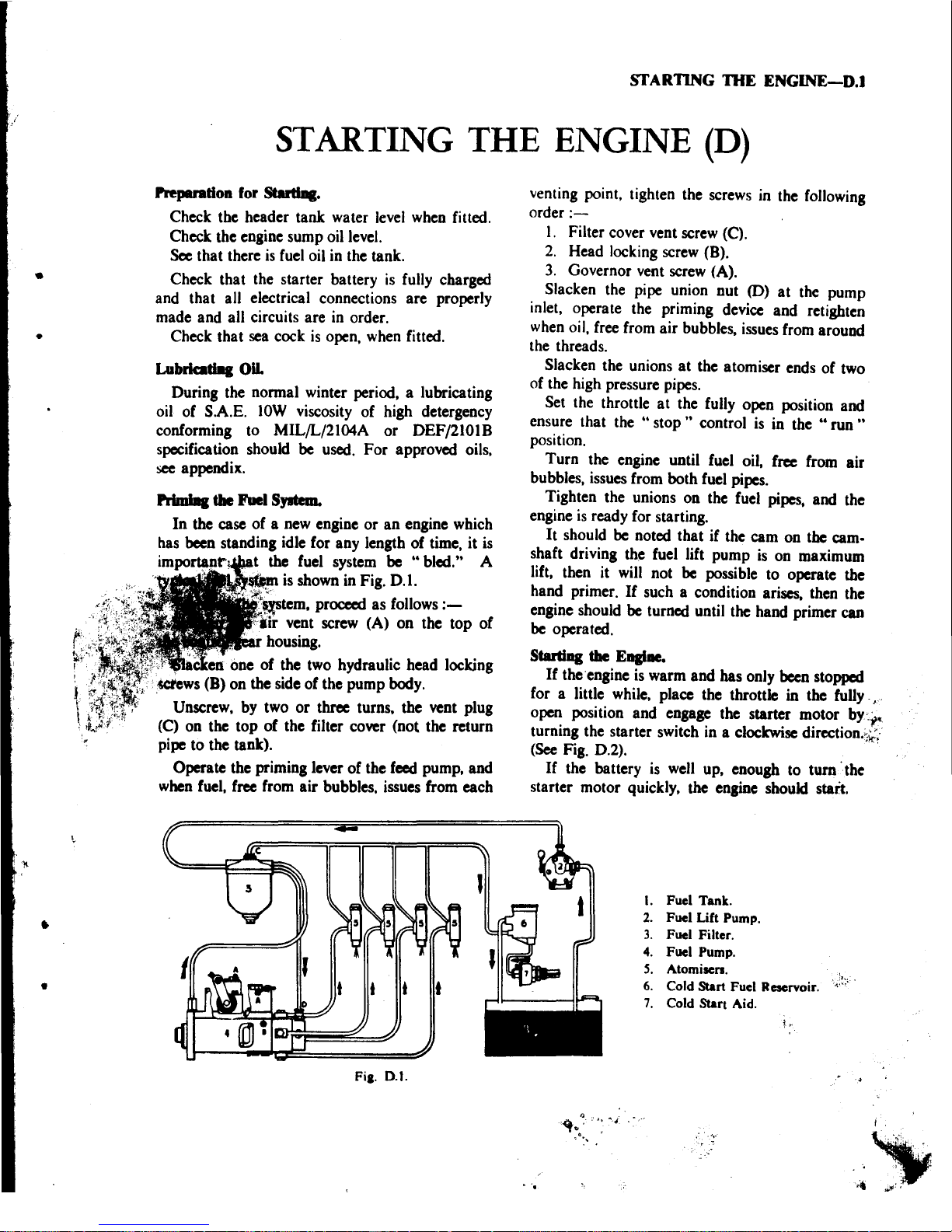
PrimIIIa
tile Fuel S,.tem.
In
the case
of
a new engine
or
an
engine which
has been standing idle for any length
of
time. it
is
the fuel system
be
..
bled." A
Pltl5lP./NiUI is shown in Fig. 0.1.
":'
$,lfSu:m,
proceed as follows
:-
vent screw (A)
on
the
top
of
housing.
5llCktID one
of
the two hydraulic head locking
"
_ws
(B)
on
the side
of
the pump body.
, Unscrew, by two
or
three turns, the vent plug
(C) on the
top
of
the filter cover (not the return
pipe to the tank).
Operate the priming lever
of
the feed pump, and
when fuel, free from
air
bubbles. issues from each
Fia.O
.l.
venting point. tighten the screws in the following
order
:-
I, Filter cover vent screw (C).
2.
Head locking screw (B).
3.
Governor vent screw (A).
Slacken the pipe union nut
(0)
at
the pump
inlet. operate the priming device and retighten
when oil. free from
air
bubbles. issues from around
the threads.
Slacken the unions
at
the atomiser ends
of
two
of the high pressure pipes.
Set the throttle
at
the fully open position and
ensure that the ..
stop"
control
is
in the ..
run
..
position.
Turn
the engine until fuel oil, free from air
bubbles. issues from both fuel pipes.
Tighten the unions
on
the fuel
pipes.
and the
engine
is
ready for starting.
It
should
be
noted that if the cam on the cam·
shaft driving the fuel lift pump
is
on maximum
lift. then it will not
be
possible to operate the
hand primer.
If
such a condition arises. then the
engine should
be
turned until the hand primer
can
be
operated.
Starting
the
E
......
If
the'engine is warm
and
has only
been
stopped
for a little while. place the throttle in the fully ."
open position and engage the starter motor
by
'
~
turning the starter switch in a clockwise
direction.
~.;;~'
(See Fig. 0.2). ,
If
the battery
is
well up. enough to turn the
starter motor quickly. the engine should start.
1.
Fuel Tank.
2.
Fuel Lift Pump.
3. Fuel Filter.
4.
Fuel Pump.
S.
Atomisen.
6. Cold Start Fuel Reservoir.
7.
Cold Start Aid.
~
i
,.:
.,;
,
.
I
'"
. '
''
, ..
...
...
'·4
~
..
;;
..
'. "

•
•
I)
•
HULLS
#1 - 4
l"Headstay
1
Backsta
2
Main
upper
2 Main
lower
2 Lower
1
ay
lntermediate
HULLS
#6
and
up
1
Headstay
1
Backstay
2
Main
upper
2
Main
lower
2 Lower
1
Midstay
2
Intermediates
HULLS
#1 - 4
1
adstay
1 Bac
ay
2 Main
upp
2 Main Lower
2 Lower
1
Midstay
2
Intermediates
2
Mizzen
foresta
2
Mizzen
uppe
2
Mizzen
ers
1
Mi
z
~
.
err
jumper
l -
Mizzen
backstay
CAL
2-46
STANDING
RIGGING
SLOOP
RIG
5/16"
"
7/32"
"
5/16"
"
"
3/8"
"
7/32"
"
1.
~~
. 1
1/2"
M.E. & M.E.
~52'4"
M.E. & M.E.
1 x 19 x
22'S
1/2"
M.E. & M.E.
19 x
22'9
1/2"
M.E. & M.E.
~x-~~~lL~2:"_~M.E.
& M.E.
x 19 x
22'7
1/2"
M.E. &
Fork
x
19
x
10'6
1/2"
M.E. & M.E.
1 x 19 x
48'9
1/2"
M.E. &
5/8"
RH
Stud
1 x 19 X
53'0"
M.E. &
5/8"
RH
Stud
1 x 19 x
22'S
1/2"
M.E. & M.E.
1 x 19 x
23'S
1/2"
M.E. &
5/8"
RH
Stud
1 x 19 x
22'9
1/2"
M.E. &
5/8"
RH
Stud
1 x 19 x
23'2"
Fork
&
3/8"
RH
Stud
1 x 19 x
10'11"
M.E. &
3/8"
RH
Stud
CAL
2-46
STANDING
RIGGING
KETCH
RIG
5/16"
"
"
3/8"
"
"
"
5/32"
7/32"
1 x 19
1 x 19
1 x 19
72"
M.E. & M.E.
50'
'M.E.
& M.E.
2'5
1/2"
M.E. & M.E.
22'9
1/2"
M.E. & M.E.
22'
1
1/2"
M.E. & M.E.
21'
3
1/2"
M.E. &
Fork
x
10'6
1/2"
M.E. & M.E.
, 4
1/2"
M.E. &
M.E.
2" M.E. & M.E.
1
1/2
E.
& M.E.
1 x
19 11
1/2"
. &
5/16"
RH
Stud
1 x 19 x
30'6"
M.E. &
3/8"
RH
Stud
-
-----------
---
•
•
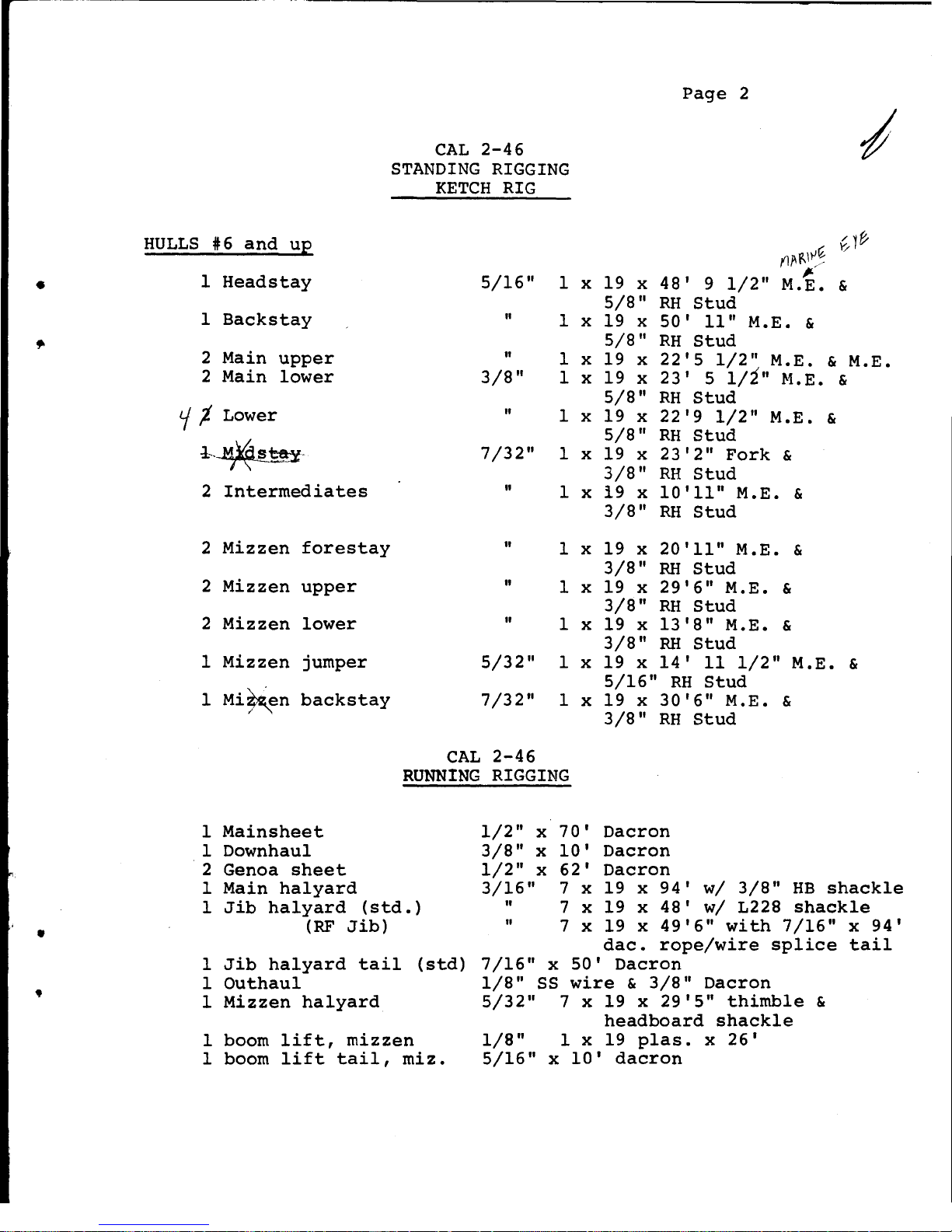
HULLS
#6
and
up
1
Headstay
1
Backstay
2 Main
upper
2
Main
lower
CAL
2-46
STANDING
RIGGING
KETCH
RIG
5/16"
1 x
II
1 x
II
1 x
3/8"
1 x
19 X
5/8"
19 X
5/8"
19 x
19 x
Page
2
{,,1(/
M{I,\)i~
~ /
48'
9
1/2"
M.E. &
RH
Stud
50'
11"
M.
E.
&
RH
Stud
22'5
1/2"
M.E. & M.E.
23'
5
l/ill
M.E. &
RH
Stud
tf
j. Lower " 1 x
5/8
11
19 x
5/8"
22'9
1/2"
M.E. &
RH
Stud
l
'-
~Sru
-
7/32"
2
Intermediates
"
2
Mizzen
forestay
"
2
Mizzen
upper
"
2
Mizzen
lower
"
1
Mizzen
jumper
5/32"
1
Mi~en
backstay
7/32
11
1 x 19 x
23'2"
Fork
&
3/8"
RH
Stud
1 x 19 x
10'11"
M.E. &
3/8"
RH
Stud
1 x 19 X 20'1111 M.E. &
3/8"
RH
Stud
1 x 19 x
29'6"
M.E. &
3/8"
RH
Stud
1 x 19 x
13'8"
M.E. &
3/8"
RH
Stud
1 x 19 x
14'
11
1/211 M.E. &
5/16"
RH
Stud
1 x 19 x
30'6"
M.E. &
3/8"
RH
Stud
CAL
2-46
RUNNING
RIGGING
1
Mainsheet
1 Downhau1
2 Genoa
sheet
1 Main
halyard
1
Jib
halyard
(std.)
(RF
Jib)
1
Jib
halyard
tail
(std)
1
Outhau1
1
Mizzen
halyard
1 boom
lift,
mizzen
1 boom
lift
tail,
miz.
1/2"
X
3/8"
x
1/2"
x
3/16"
II
"
70'
Dacron
10'
Dacron
62'
Dacron
7 x 19 x
94'
w/
3/8
11
HB
shackle
7 x 19 x
48'
w/
L228
shackle
7 x 19 x
49'6"
with
7/16"
x
94'
dac.
rope/wire
splice
tail
7/16
11
x
50'
Dacron
1/8"
SS
wire
&
3/8"
Dacron
5/32"
7 x 19 X
29'S"
thimble
&
headboard
shackle
1/8"
1 x 19
p1as.
x
26'
5/16"
x
10'
dacron

1
Boom
lift,
main
1
Boom
lift
tail,
1
Mizzen
staysai1
(optional)
1
Mizzen
sheet
•
,
Page
3
CAL
2-46
RUNNING
RIGGING
3/16"
1 x 19
p1as.
main
3/8"
x
15
t
Dacron
hal
3/8"
x
65'
Dac wi 2
7/16"
x
42'
Dacron
x
42'
1/2"
t
(5.
&
K)
snap
shackle
Table of contents
Other Jensen Marine Boat manuals

Popular Boat manuals by other brands

Mercury
Mercury Dynamic 250/260 manual

Dufour Yachts
Dufour Yachts 365 Grand Large owner's manual

Kangui SURF
Kangui SURF Maui Installation instructions & user guide

Oru Kayak
Oru Kayak COAST XT Assembly guide

Walker Bay
Walker Bay Genesis Console 310 Assembling instructions

Bayliner
Bayliner 197 owner's manual


