Dufour Yachts 365 Grand Large User manual

ENGLISH 18.11.08
A09
OWNER’S MANUAL

ENGLISH 2008-11-18 Page 2 / 80
DUFOUR 365

ENGLISH 2008-11-18 Page 3 / 80
DUFOUR 365
Your agent
Name
is DUFOUR YACHTS’ representative and will give you all the help you need to solve any
difficulties you might have during launching and masting of your boat, as well as for
commissioning and maintenance technical checks. If necessary, he will help you with the
administrative process of registering your boat.
As soon as you become the owner, familiarize yourself with the manual supplied with your boat,
sign and date the receipt acknowledgements below, and give (or send) the last one to your agent.
Owner's Manual receipt acknowledgement to be kept in your Manual
I, the undersigned:
Name
Address
owner of DUFOUR 365 no.
confirm that I have received the Owner’s Manual for my DUFOUR 365 and accept its
being written in English.
Dated:
Signature:
Detach along dotted line
…………………………………………………………………………………………………………………
Owner’s Manual receipt acknowledgement to be returned to DUFOUR YACHTS
1, Rue Blaise Pascal- 17187 PERIGNY CEDEX- FRANCE
I, the undersigned:
Name
Address
owner of DUFOUR 365 no.
confirm that I have received the Owner’s Manual for my DUFOUR 365 and accept its
being written in English.
Dated:
Signature:

ENGLISH 2008-11-18 Page 4 / 80
DUFOUR 365

ENGLISH 2008-11-18 Page 5 / 80
DUFOUR 365
CONTENTS
INTRODUCTION____________________________________________________________________________7
I. GENERAL INFORMATION __________________________________________________________8
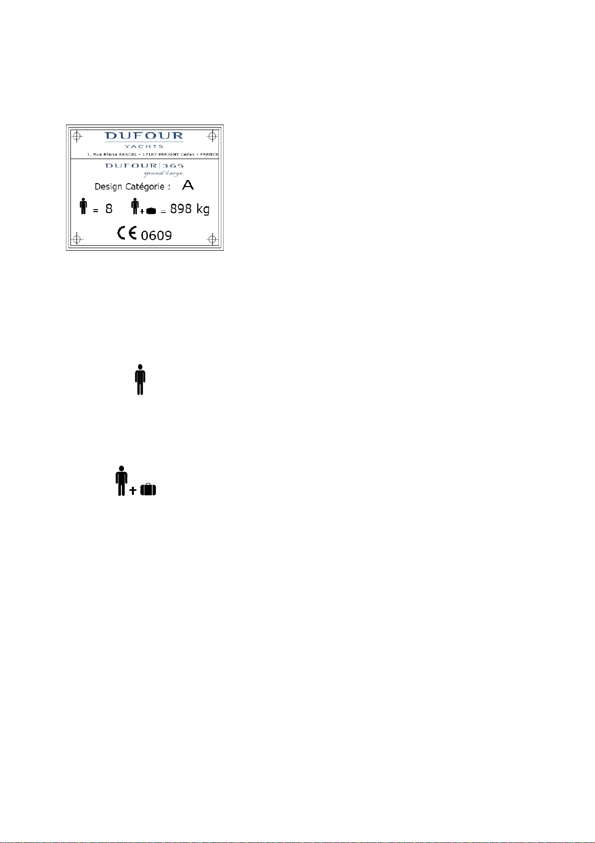
A. Design category _____________________________________________________________________8
B. Certification ________________________________________________________________________8
C. Identification _______________________________________________________________________ 8
D. Builder's plate ______________________________________________________________________ 9
II. PRINCIPAL SPECIFICATIONS______________________________________________________10
III. ELECTRICAL SYSTEMS____________________________________________________________11
A. Safety and operating instructions for the electrical system _________________________________ 11
B. Installing new equipment ____________________________________________________________ 11
C. Batteries __________________________________________________________________________12
D. Electric windlass____________________________________________________________________12
E. 220 / 110 Volt installation ____________________________________________________________13
IV. GAS INSTALLATION_______________________________________________________________ 14
A. Operating advice ___________________________________________________________________ 14
B. Checking the system ________________________________________________________________15
C. Changing the gas cylinder____________________________________________________________15
V. DRAIN & SANITATION SYSTEM ____________________________________________________ 16
A. Specifications of the drain system _____________________________________________________ 16
B. Pressurized fresh-water pump ________________________________________________________ 16
C. Seacocks __________________________________________________________________________17
D. Operation of the sea toilets ___________________________________________________________17
VI. FLOODING _______________________________________________________________________ 18
VII. FIRE PROTECTION _______________________________________________________________ 18
A. Installation ________________________________________________________________________ 18
B. Safety instructions __________________________________________________________________19
VIII. ENGINE__________________________________________________________________________20
A. General precautions_________________________________________________________________ 20
B. Exhaust gas emission________________________________________________________________20
C. Safety_____________________________________________________________________________20
D. Wintering _________________________________________________________________________21
IX. FUEL INSTALLATION _____________________________________________________________21
X. STEERING SYSTEM _______________________________________________________________ 21
A. Steering wheel _____________________________________________________________________21
B. Emergency tiller____________________________________________________________________21
XI. SAILING _________________________________________________________________________ 22
XII. LIGHTNING PROTECTION _________________________________________________________23
A. Maintenance_______________________________________________________________________23
B. Protection of persons during a storm___________________________________________________ 23
XIII. ENVIRONMENTAL PROTECTION & SAFETY_________________________________________23
XIV. SAFETY FACILITIES ______________________________________________________________24
XV. HANDLING, TRANSPORTING, HAULOUT ____________________________________________25
XVI. GUARANTEE CONDITIONS, TRANSFER OF OWNERSHIP ____________________________26
I. Presentation plan___________________________________________________________________ 30

ENGLISH 2008-11-18 Page 6 / 80
DUFOUR 365
II. Accommodation layout ______________________________________________________________ 31
III. Deck fittings plan___________________________________________________________________32
IV. Sail plan __________________________________________________________________________ 34
V. Halyard & sheet routing diagram ______________________________________________________36
VI. 110 V circuit diagram _______________________________________________________________38
VII. 220 V circuit diagram _______________________________________________________________40
VIII. Charging & power circuit diagram_____________________________________________________42
IX. 12 V / 220 V Electrical panel diagram __________________________________________________44
X. Distribution panel terminal rail diagram ________________________________________________ 46
XI. 12 V electrical installation diagram ____________________________________________________ 48
XII. 220 V electrical installation diagram ___________________________________________________ 50
XIII. Steering system diagram _____________________________________________________________52
XIV. Gas system diagram _________________________________________________________________ 54
XV. Abandon ship plan__________________________________________________________________ 56
XVI. Fresh-water system diagram __________________________________________________________58
XVII. Drain system diagram _______________________________________________________________60
XVIII. Skin fitting location diagram__________________________________________________________62
XIX. Mechanical installation diagram_______________________________________________________64
XX. Holding tank fitting drawing - layout 3 cabins____________________________________________ 66
XXI. Holding tank fitting drawing - layout 2 cabins____________________________________________ 68
XXII. Sea and inland waterways charter______________________________________________________ 70
XXIII. S.N.S.M. __________________________________________________________________________71

ENGLISH 2008-11-18 Page 7 / 80
DUFOUR 365
I
IN
NT
TR
RO
OD
DU
UC
CT
TI
IO
ON
N
DUFOUR YACHTS is pleased to present you with this Manual which will help you get to
know your boat better.
This manual has been produced to help you enjoy the use of your boat in complete safety. It
contains details about on board fittings and installations as well as information about use and
maintenance. Read it carefully, in particular to avoid fire and flooding risks, and familiarize
yourself with your boat before using it.
If this is your first boat, or if you are changing to a type of boat you are unfamiliar with, for your
convenience and safety, make sure you gain experience in handling and use before taking
command of your boat. Your agent, your national yachting federation or your yacht club will be
more than happy to recommend local sailing schools or qualified instructors.
KEEP THIS MANUAL IN A SAFE PLACE AND PASS IT ON TO THE NEW OWNER
IF YOU SELL YOUR BOAT.
NOTICE: Our boats are regularly improved in the light of our customers’ experiences and
research by the shipyard, and so the specifications given in this Owner’s Manual are not
contractually binding and may be changed without notice and without any obligation to
update.
This manual is intended to cover as much information as possible, so certain equipment or
paragraphs might not apply to your boat. In case of doubt, please refer to the inventory which
should have been given to you by your agent when you placed your order.

ENGLISH 2008-11-18 Page 8 / 80
DUFOUR 365
I
I.
.
G
GE
EN
NE
ER
RA
AL
L
I
IN
NF
FO
OR
RM
MA
AT
TI
IO
ON
N
A
A.
.
D
DE
ES
SI
IG
GN
N
C
CA
AT
TE
EG
GO
OR
RY
Y
Your DUFOUR 365 comes under the OCEAN-GOING design category A.
Under normal conditions of use, your boat is designed to sail in waves higher than 4 m and winds
that are stronger than force 8 (Beaufort scale), for which is it largely self-sufficient.
This sailing capability is equally dependent on the skills of the crew, their physical
capacities, the maintenance of the boat and its equipment.
So always take care before putting to sea.
DUFOUR YACHTS is not able to guarantee perfect functioning of the boat in exceptional sea
conditions (violent storms, hurricanes, cyclones, waterspouts, etc.)
SUMMARY OF DESIGN CATEGORIES
Design
categor
y
Type of sailing Wind strength
(Beaufort) Wind
speed Effective wave height
to be taken into account
AOcean-going Superior to 8 Stronger than 21m/s Higher than 4 m
BOpen sea Up to and including 8 Up to 21m/s Up to and including 4 m
CInshore Up to and including 6 Up to 17 m/s Up to and including 2 m
DSheltered waters Up to and including 4 Up to 13 m/s Up to and including 0.5 m
B
B.
.
C
CE
ER
RT
TI
IF
FI
IC
CA
AT
TI
IO
ON
N
For ships with hulls shorter than 12 m, European Directive requires category A bis (auto-
certification plus stability and buoyancy evaluation by specified organism).
IMCI (International Marine Certification Institute) was responsible for certification. (refer to
Safety Compliance Declaration)
C
C.
.
I
ID
DE
EN
NT
TI
IF
FI
IC
CA
AT
TI
IO
ON
N
The hull identification number is located on starboard side of transom. It contains a series of
letters and numbers that begin with FR-DUF...

ENGLISH 2008-11-18 Page 9 / 80
DUFOUR 365
D
D.
.
B
BU
UI
IL
LD
DE
ER
R'
'S
S
P
PL
LA
AT
TE
E
Design category = A : Ocean-going (see 1.1)
Max. number of people = 8
Max. additional load = 898 kg
CE 0609
The Builder’s identification plate is located in the cockpit.
It carries important information, which is explained
below.
: Recommended by the builder for navigation in sea
conditions for category for which it was built.
: includes 8 people with equipment, personal belongings
and supplies (not including various tank capacities (water,
diesel fuel, etc.)) )
:CE mark indicating that the boat complies with all the
requirements of the Directive. The sequence of numbers
is the Certification institution's code. In this case IMCI
(International Marine Certification Institute),
Brussels (refer to Safety Compliance Declaration)

ENGLISH 2008-11-18 Page 10 / 80
DUFOUR 365
I
II
I.
.
P
PR
RI
IN
NC
CI
IP
PA
AL
L
S
SP
PE
EC
CI
IF
FI
IC
CA
AT
TI
IO
ON
NS
S
Model: DUFOUR 365
Designer: Umberto Felci
Design category A
Notified body no. CE/0609
LOA: 10.81 m
Hull length: 10.53 m
LWL: 9.26 m
Maximum beam: 3.65 m
Draught (shallow / deep keel): 1.70 m / 1.90m
Mast height clearance: 15.00 m
Ballast weight: 1,740 kg / 1,650 kg
Light displacement (incl. safety equipment): 6,485 kg
Displacement at maximum loading: 7,723 kg
Standard mainsail area (approximate) 28.50 m²
Roller-furl genoa area (approximate) 33.00 m²
Water capacity excluding water-heater
(approximate) 265 L
Diesel capacity (approximate) 90 L
Holding tank (option) 55 L
Engine battery 75 Ah
Auxiliary battery (standard version) 100 Ah
Primary means of propulsion Sail
Maximum permissible engine power 30 kW
NB: due to the trim and loading of the boat, is it not usually possible to use the whole of the
various tank capacities for fresh water and diesel. You are recommended to maintain a
diesel reserve of 20%.

ENGLISH 2008-11-18 Page 11 / 80
DUFOUR 365
I
II
II
I.
.
E
EL
LE
EC
CT
TR
RI
IC
CA
AL
L
S
SY
YS
ST
TE
EM
MS
S
A
A.
.
S
SA
AF
FE
ET
TY
Y
A
AN
ND
D
O
OP
PE
ER
RA
AT
TI
IN
NG
G
I
IN
NS
ST
TR
RU
UC
CT
TI
IO
ON
NS
S
F
FO
OR
R
T
TH
HE
E
E
EL
LE
EC
CT
TR
RI
IC
CA
AL
L
S
SY
YS
ST
TE
EM
M
WARNING
Always:
- Check the condition of the batteries (charge and electrolyte level) and the charging
system before putting to sea.
- Disconnect and remove batteries for wintering.
- Do not let battery voltage drop below 10.5V during wintering.
- Carry spare lamps for all navigation lights and
interior lighting. Respect power ratings, particularly for navigation lights.
- Check operation of the navigational instruments.
- Check operation of navigation lights before night sailings
Never:
- Work on an electrical installation that is live.
- Make any modification to an installation and the relevant diagrams, unless it is
carried out by an electrician qualified in marine electrics. Have the system checked
every 2 years.
- Change or modify the breaking capacity of overload protection devices.
- Install or replace electrical apparatus or equipment with units
exceeding the circuit’s rated current capacity.
- Leave the boat unattended with the electrical installation powered,
except for the automatic bilge pump and the fire or intrusion protection circuits,
where applicable.
If a fuse or circuit-breaker blows continually, you should consult a specialist to determine
the cause of the short-circuit.
B
B.
.
I
IN
NS
ST
TA
AL
LL
LI
IN
NG
G
N
NE
EW
W
E
EQ
QU
UI
IP
PM
ME
EN
NT
T
Since 1 January 1996, electrical equipment is subject to the European “electromagnetic
compatibility” directive (Ref 89/336/CEE). So new equipment being installed must meet
this standard and bear the CE mark. Equipment must also be supplied with a compliance
certificate and instructions for use.
In the case of 220 or 110 V installations, use only double-insulated or earthed equipment.
When such equipment is being installed, respect the fitting instructions (conductor size,
protection).
To avoid maintenance problems, be sure to mark in the manual any modifications that may
be made to the electrical circuit diagram.

ENGLISH 2008-11-18 Page 12 / 80
DUFOUR 365
C
C.
.
B
BA
AT
TT
TE
ER
RI
IE
ES
S
The battery capacity has been designed to meet the power requirements of the on-board
accessories. To avoid any problems, it is necessary to keep a close eye on the maintenance
and correct charging of the batteries.
NOTE
- When installing new electrical appliances, take care that the overall consumption of
these appliances remains within the capacity of your batteries.
-Always disconnect the negative (-) battery terminal before the positive (+) terminal.
-Never allow a conductive object (tools, etc.) to bridge across the two battery terminals.
-When handling batteries, keep them horizontal to avoid spillage of electrolyte. Wear
gloves and protective clothing that will prevent any risk of contact with electrolyte in
the event of a leak.
-In the event of electrolyte splashes, rinse the affected part of the body copiously and
consult a doctor.
D
D.
.
E
EL
LE
EC
CT
TR
RI
IC
C
W
WI
IN
ND
DL
LA
AS
SS
S
NOTE
It is essential to run the engine with the throttle slightly open when using the electric
windlass.

ENGLISH 2008-11-18 Page 13 / 80
DUFOUR 365
E
E.
.
2
22
20
0
/
/
1
11
10
0
V
VO
OL
LT
T
I
IN
NS
ST
TA
AL
LL
LA
AT
TI
IO
ON
N
-Your boat is delivered without a supply cable or shore connection plug. The cable used
must be designed for exterior use. Its cross-sectional area must be appropriate for its
length and the rating of the main circuit-breaker (see electrical diagram). The plug
must be suitable for the socket on the shore (if necessary, seek the advice of a
professional). It should be as close as possible to the IP 67 / IEC529 type
-Disconnect the boat’s power supply when system is not in use.
-Connect the metal cases or housings of installed electrical equipment to the ship’s
protective conductor (green or green / yellow wire).
-Use double-insulated or earthed electrical appliances.
WARNING
In order to minimize the risk of electric shock or fire:
-Switch off the shore supply at the on-board isolator before connecting or
disconnecting the shore/boat supply cable.
-Connect the shore/boat supply cable at the boat end before connecting it to
the shore outlet
-Disconnect the shore/boat supply cable at the shore outlet before
disconnecting it at the boat end
-Close the shore outlet cover properly
-Do not make modifications to the shore supply cable; use only compatible
connectors.
WARNING
Never let the end of a ship/shore supply cable dangle into the water. It may create an
electrical field that could injure or kill nearby swimmers.

ENGLISH 2008-11-18 Page 14 / 80
DUFOUR 365
I
IV
V.
.
G
GA
AS
S
I
IN
NS
ST
TA
AL
LL
LA
AT
TI
IO
ON
N
A
A.
.
O
OP
PE
ER
RA
AT
TI
IN
NG
G
A
AD
DV
VI
IC
CE
E
-Read carefully all instructions for cooker and regulator before use or maintenance.
-Ensure that the gas cylinder and regulator are in accordance with the requirements of
the cooker (flow rate, pressure, type of gas) and with the regulations in force in the
country where it is being used.
-Make sure the appliance gas taps are closed before opening the valve on the cylinder.
ATTENTION!
Appliances that burn fuel use up the oxygen in the cabin and release
combustion products into the boat. Ventilation is required when appliances are alight. Open
the coachroof ports while you are cooking.
-Do not use the stove as a means of heating.
-Do not obstruct quick access to the elements of the gas installation (cylinder locker,
shut-off valve).
-The gas cylinder must always be stowed in the sealed, ventilated space provided. The
same applies to spare or empty cylinders. No other equipment must be stowed in this
space.
ATTENTION!
Never leave the boat unattended when gas appliances are alight.
- Close all valves in the circuit when the boat is left empty (shut-off valve, regulator
valve), even if the cylinder is believed to be empty.
- After the boat has been shut up, never smoke when going below, and ensure that there
is no smell of gas.
- If you smell gas, close the circuit valves and the cooker taps, ventilate the boat, and
find the leak before using the installation again.
WARNING
In the event of an emergency, the circuit valves must be closed immediately.

ENGLISH 2008-11-18 Page 15 / 80
DUFOUR 365
B
B.
.
C
CH
HE
EC
CK
KI
IN
NG
G
T
TH
HE
E
S
SY
YS
ST
TE
EM
M
- The gas system must be tested periodically:
°Close all the cooker taps.
°Open the cooker supply and regulator valves.
°Check all connections are gas-tight using a leak detector or by applying soapy
water.
ATTENTION!
Do not use solutions containing ammonia.
DANGER!
Never use a flame to look for leaks.
Repairs and modifications to the system should be carried out by a qualified person.
Flexible hoses must be:
-Checked regularly, at least once a year,
-Replaced if the expiry date marked on the hose is passed,
-Replaced five years after the date of manufacture that may be marked on them,
-Replaced in the event of damage.
C
C.
.
C
CH
HA
AN
NG
GI
IN
NG
G
T
TH
HE
E
G
GA
AS
S
C
CY
YL
LI
IN
ND
DE
ER
R
ATTENTION!
-Close the cooker taps and supply shut-off valve.
- Do not smoke nor use an open flame while the gas cylinder is being replaced.

ENGLISH 2008-11-18 Page 16 / 80
DUFOUR 365
V
V.
.
D
DR
RA
AI
IN
N
&
&
S
SA
AN
NI
IT
TA
AT
TI
IO
ON
N
S
SY
YS
ST
TE
EM
M
A
A.
.
S
SP
PE
EC
CI
IF
FI
IC
CA
AT
TI
IO
ON
NS
S
O
OF
F
T
TH
HE
E
D
DR
RA
AI
IN
N
S
SY
YS
ST
TE
EM
M
Pump type Theoretical flow rate
Manual 40.5 l / 45 strokes/min
Electric 15 l / min
Read carefully the operating and maintenance instructions for the bilge pump that goes
with your boat.
WARNING!
- Ensure that bilge pumps are in working order before putting to sea.
- Know where to find the hand pump and its handle
- Know where to find the switch for the electric pump on the electrical panel
- Clean the well and pump filters regularly
- The bilge pump system is not designed for keeping the boat afloat in the event of damage.
It is intended to remove water coming from spray, leaks from seacocks or any other
moderate leaks.
B
B.
.
P
PR
RE
ES
SS
SU
UR
RI
IZ
ZE
ED
D
F
FR
RE
ES
SH
H-
-W
WA
AT
TE
ER
R
P
PU
UM
MP
P
Fresh water is supplied to the sink and washbasins by an electric pump. A filter is
installed upstream of the pump, and must be cleaned regularly.
Never allow the pump to run if the tank is empty. Change over to the other tank or
fill up.
Hot water is produced by a water-heater connected to the engine cooling circuit and the
shore electric supply.
After the water-heater has been emptied, make sure that the element is covered before
power is re-applied.

ENGLISH 2008-11-18 Page 17 / 80
DUFOUR 365
C
C.
.
S
SE
EA
AC
CO
OC
CK
KS
S
Seacocks are of the ¼-turn type:
- OPEN position: handle in line with seacock body,
- CLOSED position: handle perpendicular to seacock body.
ATTENTION!
- Never interfere with the tightening of the seacocks to the hull. In the event of a leak,
consult a professional.
- In bad weather or when leaving your boat, close all the sanitation system seacocks.
- Keep seacocks closed when not being used.
- During wintering, clean and rinse the seacocks and skin fittings. Inspect brass fittings;
slight surface corrosion is normal.
- In the event of more serious corrosion, consult your agent.
D
D.
.
O
OP
PE
ER
RA
AT
TI
IO
ON
N
O
OF
F
T
TH
HE
E
S
SE
EA
A
T
TO
OI
IL
LE
ET
TS
S
- Open the sea-water inlet seacock.
- Open the bowl emptying seacock.
- Set the lever to the “FLUSH” position.
- Operate the pump.
- To empty the bowl and avoid any water slopping when heeling, set the lever to the
“DRY BOWL” position.
-Operate the pump until the bowl is dry.
- Repeat these flushing / emptying operations as many times as is necessary to ensure
complete emptying of the pipes.
When toilets are not being used, set the lever to the «DRY BOWL» position, or the
«CLEF» position for certain models.
- Close seacocks after use, as the toilet is below the waterline.
- Change the toilet seals regularly.
Vanne ouverte Vanne fermée
OPEN position CLOSED position

ENGLISH 2008-11-18 Page 18 / 80
DUFOUR 365
V
VI
I.
.
F
FL
LO
OO
OD
DI
IN
NG
G
Boat flooding risks:
- Before putting to sea, always check that portholes, deck hatches and any other
openings that could allow flooding are shut.
- When under sail, close all seacocks, except the engine water intake.
- Periodically check:
- Skin fittings, seacocks and pipes are watertight
- Proper emptying of the cockpit drains.
-Watertightness of the stern gland.
WARNING!
Cockpit locker lids must be fastened shut before putting to sea. This is particularly
important for those lockers representing a significant flooding risk (e.g. starboard helm seat
locker)
V
VI
II
I.
.
F
FI
IR
RE
E
P
PR
RO
OT
TE
EC
CT
TI
IO
ON
N
A
A.
.
I
IN
NS
ST
TA
AL
LL
LA
AT
TI
IO
ON
N
- Fire-extinguishers are subject to national regulations, and for this reason they are
not supplied with your boat.
- We recommend you to equip your boat with fire extinguishers meeting the ISO
9094-1 standard, with the following specifications:
a) Minimum capacity per extinguisher: 5A/34B,
b) Minimum combined extinguisher capacity: 10A/68B,
c) 1 extinguisher within:
- 1 m of cockpit for boats <10 m or 2 m for boats >10m
- 2 m of the extinguisher opening for dowsing the engine,
d) 1 extinguisher within 2 m of the cooker,
e) 1 extinguisher within 5 m of the bunks.
f) CO2extinguishers may be placed in accommodation areas only where flammable
liquids are present (e.g. galley) or where there is powered electrical equipment.
There must not be more than one CO2extinguisher per area at risk, and its
maximum capacity must not exceed 2 kg.
Only compatible replacement parts must be used in fire protection systems. They must
bear the same markings and be technically equivalent.
In addition, a fire blanket should be stored close to the galley — very useful
particularly in the event of a pan fire involving oil.

ENGLISH 2008-11-18 Page 19 / 80
DUFOUR 365
B
B.
.
S
SA
AF
FE
ET
TY
Y
I
IN
NS
ST
TR
RU
UC
CT
TI
IO
ON
NS
S
NOTE
It is the responsibility of the owner / skipper to:
- Have fire-fighting equipment checked in accordance with the stipulations of the
builder and the regulations in your country.
- Replace fire-fighting equipment if it has expired or been discharged, by
extinguishers of equal or greater capacity.
- Show members of the crew:
•The location and operation of fire-fighting equipment
•The location of the engine compartment extinguishing hole (located on the
companionway)
- Ensure that fire-fighting equipment is readily accessible whenever the boat is
occupied.
Never:
- modify any of the boat’s installations (especially the electrical, fuel or gas
installations) or allow any unqualified person to modify these installations.
- Obstruct gangways to emergency exits (deck hatches)
- Obstruct safety controls (gas valves, fuel valves, electrical switches).
- Obstruct fire extinguisher stowages.
- Leave the boat unattended with a cooker or heater alight.
- Use a gas lamp in the boat
- Fill a fuel tank or change a gas cylinder while the engine is running, or the cooker or
heater are alight.
- Smoke while handling fuel or gas.
- Fit free-hanging curtains near the cooker or any other appliance using a naked flame.
- Store flammable products in the engine compartment.
Always keep the bilges clean and check that there is no fuel vapor or gas.
WARNING
-If a CO2extinguisher is fitted, the following information must be displayed close to its
location:
“This extinguisher contains CO2– to be used for electrical or galley fires only. To avoid
suffocation after discharging, leave the area immediately. Ventilate before re-entering.”
Do not open the engine compartment immediately after putting out a fire, to avoid the
release of toxic smoke or spraying of burning materials (oil, water).

ENGLISH 2008-11-18 Page 20 / 80
DUFOUR 365
V
VI
II
II
I.
.
E
EN
NG
GI
IN
NE
E
Regular maintenance must be carried out in accordance with the engine manufacturer’s
recommendations. Read carefully the engine operating instructions that come with the boat.
Do not hesitate to consult your agent or a qualified professional.
A
A.
.
G
GE
EN
NE
ER
RA
AL
L
P
PR
RE
EC
CA
AU
UT
TI
IO
ON
NS
S
NOTE
-Ensure that the cooling circuit water intake seacock is open, and that water is coming
out of the engine exhaust.
-Boats fitted with rotating seal stern gland: bleed the air from the gland after each
launch.
-Do not obstruct ventilation openings (vent, engine ventilation grille).
-Avoid all contact between flammable materials and hot parts of the engine.
Regularly check the condition of the anodes and ensure that they are suitable for the boat's
environment (fresh water, salt water).
Any engine change must respect the capacities of the boat and be performed by an engineer
specializing in marine mechanics.
B
B.
.
E
EX
XH
HA
AU
US
ST
T
G
GA
AS
S
E
EM
MI
IS
SS
SI
IO
ON
N
DANGER!
Internal combustion engines produce carbon monoxide. Prolonged exposure to exhaust
gasses can have serious consequences, and may even cause death.
C
C.
.
S
SA
AF
FE
ET
TY
Y
DANGER!
-In order to avoid all risk of serious injury from the propeller, the engine must not be
started when there are people swimming near the boat.
-Whenever possible, the engine must be stopped for any engine maintenance or
checking operations. If this is impossible, then particular care must be taken with
moving parts (belts, shafts, etc.) to avoid any danger of injury.
-Do not use sail and engine if the heel angle is more than 10°
Table of contents
Other Dufour Yachts Boat manuals

Dufour Yachts
Dufour Yachts 560 DUFOUR Grandlarge cruising escape User manual

Dufour Yachts
Dufour Yachts 500 Grand Large User manual

Dufour Yachts
Dufour Yachts DUFOUR 34 User manual

Dufour Yachts
Dufour Yachts 460 User manual

Dufour Yachts
Dufour Yachts Dufour 385 User manual

Dufour Yachts
Dufour Yachts 360 Grand Large User manual

Dufour Yachts
Dufour Yachts 56 Exclusive User manual

Dufour Yachts
Dufour Yachts Grand Large 445 User manual

Dufour Yachts
Dufour Yachts 40 Performance User manual

Dufour Yachts
Dufour Yachts 350 Grand Large 2015 User manual