Printed in U.S.A. Copyright © 2001, Jensen Transformers, Inc. 5
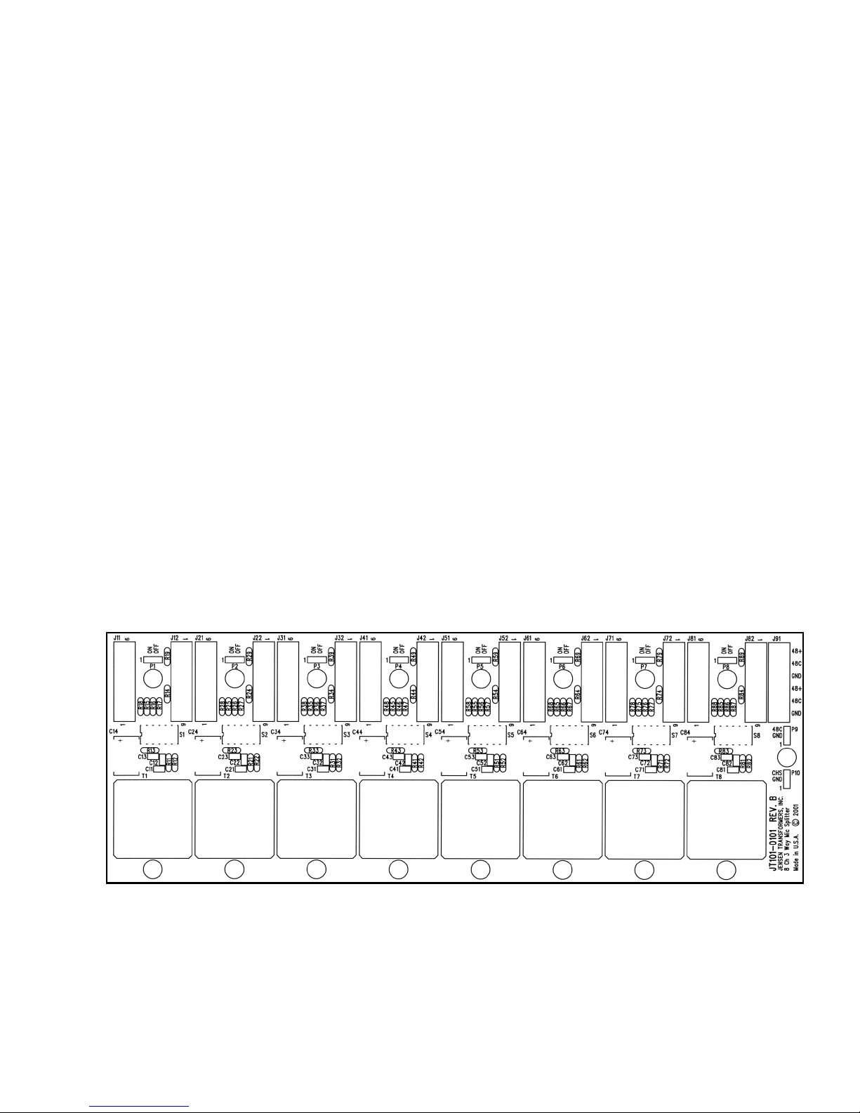
SPDT switch if phantom power must be turned on and off frequently. Components R13 and C13
provide filtering to prevent “on-off” transients and to remove any residual noise from the phantom
power supply before it reaches the microphone input. Resistor R14 discharges C13 to ground if
the connections to P1 are left open inadvertently. Resistors R15 and R16 provide the phantom
power to the microphone input and are precision matched to maintain balanced common mode
input impedances. Dipswitch positions S1-1, S1-2 and S1-3 allow the phantom power
connections to be either connected or completely disconnected from the microphone input. Under
normal circumstances, these three switches should be either all ON or all OFF.
2.1.4 Ground Lift Circuitry and Switches
Ground switching is provided for each individual input and output to allow maximum
flexibility in the grounding and termination of the splitter transformer shield connections.
Dipswitch S1-4 controls whether the microphone input shield is floating or connected to
ground through a low impedance network. Resistor R12 provides a low impedance to ground at
low frequencies and capacitor C12 provides a low impedance to ground at high frequencies when
S1-4 is in the default ON position. This low impedance network is used, instead of a hard ground
connection, to limit circulating currents between devices that might potentially create a ground loop
problem.
Dipswitch position S1-5 connects the isolated output winding shield of the microphone
splitter transformer to ground through low impedance networks consisting of R11 and C11 when
the switch is in the ON position. The default position of S1-5 is OFF, to simulate a floating
microphone at the isolated output.
2.2 Power and Ground Wiring
2.2.1 Chassis and Groundplane Connections
The JT-MS-8N2 incorporates a groundplane on the top (component side) of the printed
circuit board to provide a very low impedance for the individual input and output ground dipswitch
connections. This groundplane is normally connected to the steel chassis plate by the default
jumper connection at P10. If alternate grounding connections are required for some reason, this
jumper may be moved to its alternate position, and the groundplane connection may be hard-
wired through the GND terminals on J91.Wire sizes between 14 and 26 gauge, either stranded or
solid, may be used to make connections to the JT-MS-8N2. Stranded wire should be used if
connections will be subjected to repeated movement or vibration, to prevent breakage.
2.2.2 Phantom Power Supply Connections
The JT-MS-8N2 is designed to be used with a 48 Volt to 52 Volt phantom power supply.
Normally, a 48 Volt supply will work fine. In some cases though, when using microphones that
require the maximum 48 Volt power to be available for proper operation, the phantom power
supply may need to be adjusted to 52 Volts to overcome the slight drop in voltage that occurs
across the transient filtering network consists of R13 and C13.
A power supply with a floating (transformer isolated) secondary, such as a typical linear AC-
DC supply, should be used to prevent creating any inadvertent paths to ground. The positive
terminal of the power supply should be connected to the 48+ terminal of J91. The negative, or
common, terminal of the power supply should be connected to the 48C terminal of J91. Parallel
through connections are provided on J91 to facilitate “daisy-chaining” of the phantom power
connections when utilizing multiple JT-MS-8N2 assemblies. Wire sizes between 14 and 26 gauge,