V1.5 ©2009 JetAir Technologies, LLC - 9 -
6. Attach second Conveyor Mounting Bracket in position noted above.
7. Insert second Vertical Bent Tube and attach Inlet Bracket.
8. Attach Air Knife or JetBlast™ by inserting its inlet through inlet bracket.
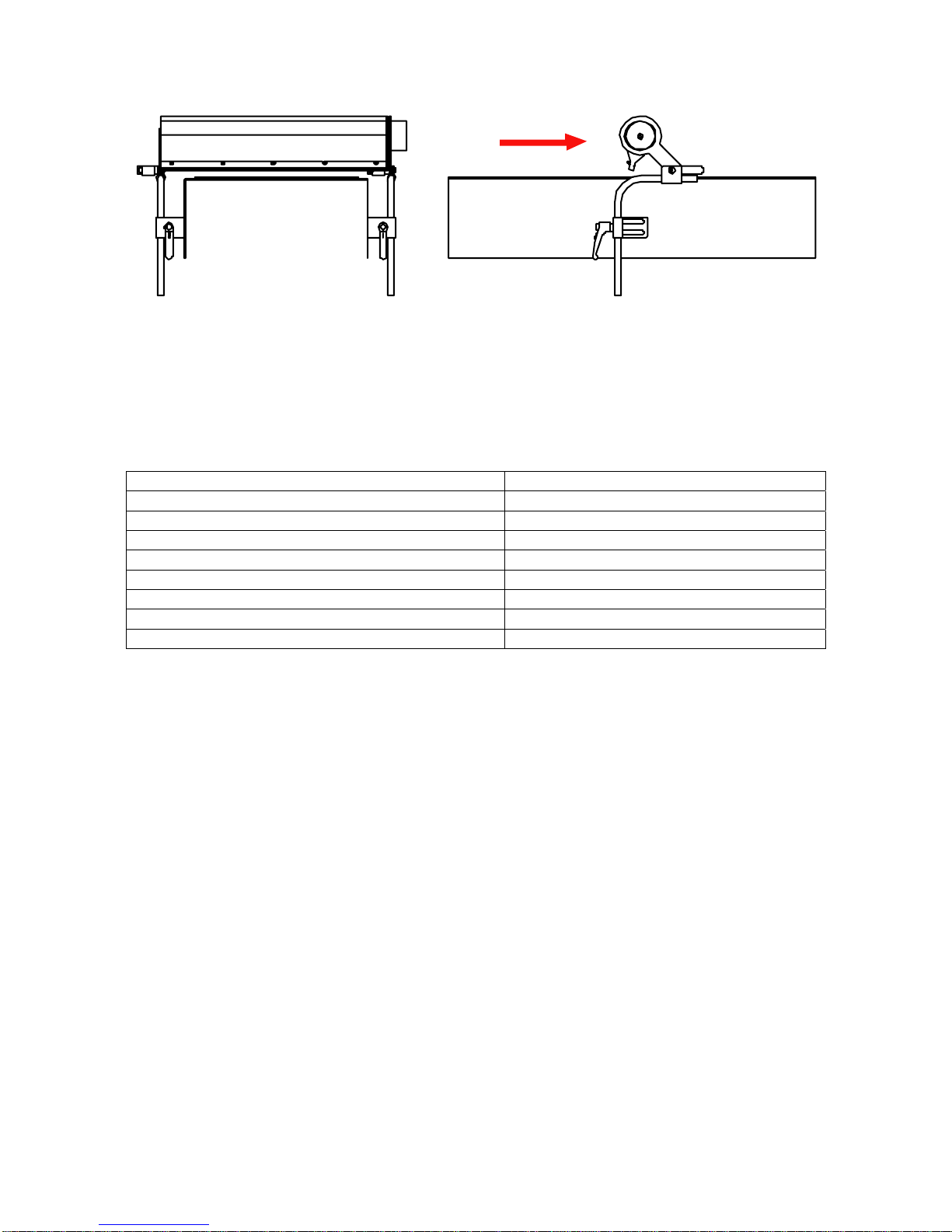
9. Adjust Air Knife or JetBlast™ into operating position by adjusting inlet and end
brackets and conveyor brackets. Typically Air Knives work best when <1”
[25mm] from object to be blown-off and rotated on its axis 15º down. AirKnife
should blow-off product first at its highest location on the product. Note: the
picture directly below shows optional Air Knife Mounting System using
Adjustable Cross Blocks instead of bent tube and adjustable brackets.
10.Tighten end bolt on Air Knife or JetBlast™ and lock into 15º position.
11.Attach Flexible Hose with Hose Clamp to Air Knife or JetBlast™ Inlet. Run hose
to Blower or manifold, avoid tight bends and minimize hose length as much as
possible. Trim and attach to blower outlet with hose clamp. Note: hose
lengths longer than 10’ should be “hard” piped with SS Tube or PVC Pipe to
minimize line friction.
To install Surface Mounted Air Components:
1. Attach one Conveyor Mounting Bracket to Conveyor.
2. Insert Vertical Bent Tube into Conveyor Mounting Bracket.
3. Attach End Bracket to Vertical Bent Tube.
4. Attach AirKnife or JetBlast™ End Bolt to End Bracket. Do not tighten end bolt
at this time.
5. Position Air Knife or JetBlast™ by hand to identify position of second conveyor
mounting bracket. Raise or lower Vertical Bent Tube in Conveyor Mounting
Bracket as needed.
6. Attach second Conveyor Mounting Bracket on opposite side of conveyor in
position noted above.
7. Insert second Vertical Bent Tube and attach Inlet Bracket.
8. Attach Air Knife or JetBlast™ by inserting its inlet through inlet bracket.
9. Adjust Air Knife or JetBlast™ into operating position by adjusting inlet and end
brackets and conveyor brackets. Typically Air Knives work best when <1”
[25mm] from object to be blown-off and rotated on its axis 15º down.