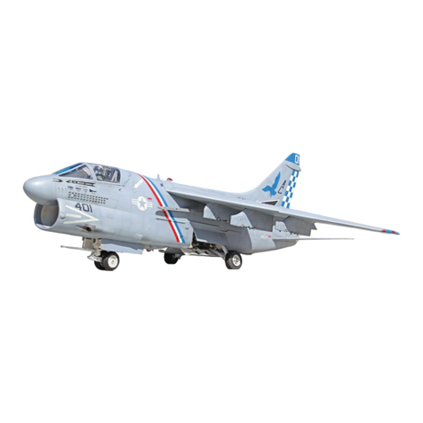
Jet Hangar A-7D/E Corsair II User manual

ASSEMBLY INSTRUCTIONS
JET HANGAR INTERNATIONAL, INC.
Post Office Box 1607
Hawaiian Gardens, CA 90716
phone: 562-467-0260
fax: 562-467-0261
www.jethangar.com

JHI-A7-06-0001
Have questions? Call us at 562-467-0260 or email larrywjhi@jethangar.com 2
TABLE OF CONTENTS
TO OUR VALUED CUSTOMERS.........................................................................4
1.0 INTRODUCTION........................................................................................5
1.1 Operation of R/C Jet Aircraft...................................................................5
1.2 The Academy of Model Aeronautics (AMA)............................................5
2.0 ABOUT THE A-7 CORSAIR II....................................................................5
3.0 GENERAL BUILDING TIPS .......................................................................6
3.1 Lightness ................................................................................................6
3.2 Adhesives ...............................................................................................6
3.3 Retracts ..................................................................................................7
3.4 Finishing .................................................................................................7
4.0 REQUIRED TOOLS AND EQUIPMENT ....................................................7
4.1 Tools ..........................................................................................................7
4.2 Adhesives...................................................................................................8
5.0 KIT CONTENTS.........................................................................................8
5.1 Turbine A-7 Packing List ............................................................................8
5.2 Ducted Fan A-7 Packing List......................................................................9
5.3 Additional Aircraft Accessories.................................................................10
5.3.1 Landing Gear........................................................................................10
5.3.2 Turbine Operation.................................................................................10
5.3.3 Ducted Fan Operation ..........................................................................10
6.0 AIRCRAFT ASSEMBLY PROCESS ........................................................11
6.1 Wing Assembly (Flaps/Ailerons)...........................................................11
6.2 Fuselage Assembly ..............................................................................12
6.2.1 Rudder ..............................................................................................12
6.2.1.1 Turbine ..........................................................................................13
6.2.1.2 Ducted Fan....................................................................................14
6.2.2 Elevator.............................................................................................15
6.2.2.1 Turbine ..........................................................................................16
6.2.2.2 Ducted Fan....................................................................................17
6.2.3 Retracts and Landing Gear ...............................................................18
6.2.4 Steering.............................................................................................21
6.2.5 Landing Gear Doors..........................................................................22
6.2.5.1 Main Gear Doors ...........................................................................22
6.2.5.2 Nose Gear Doors...........................................................................24
6.2.6 Propulsion Installation .......................................................................25
6.2.6.1 Turbine ..........................................................................................25
6.2.6.2 Ducted Fan....................................................................................27
6.2.7 Final Hardware Installation................................................................31
6.2.7.1 Turbine ..........................................................................................31
6.2.7.2 Ducted Fan....................................................................................32
7.0 AIRCRAFT SETUP AND CG ...................................................................33
8.0 FLYING THE A-7 CORSAIR II .................................................................34
8.1 Range Check ...........................................................................................34
8.2 Taxi Tests.................................................................................................34
8.3 First Flight ................................................................................................35
APPENDIX A: Coloring Diagrams/Decal Placement...........................................36
A.1 Decal Application Instructions...............................................................37

JHI-A7-06-0001
Have questions? Call us at 562-467-0260 or email larrywjhi@jethangar.com 3
A.2 Edwards Air Force Base A-7D..............................................................38
A.3 VA-72 Desert Storm CAG A-7E............................................................40
APPENDIX B: Cockpit Diagrams ........................................................................42
B.1 Assembly Notes....................................................................................43
B.2 Assembly Drawings ..............................................................................44
B.3 Cockpit References ..............................................................................49
APPENDIX C: Weapons Pylons Installation Drawings .......................................51
C.1 Assembly Notes....................................................................................52
C.2 Assembly Drawings ..............................................................................53
APPENDIX D: Landing Gear Scale Details.........................................................56
D.1 Notes ....................................................................................................57
D.1 Nose Gear ............................................................................................58
D.2 Main Gear.............................................................................................59
APPENDIX E: ARF A-7 Corsair II Plans .............................................................60

JHI-A7-06-0001
Have questions? Call us at 562-467-0260 or email larrywjhi@jethangar.com 4
TO OUR VALUED CUSTOMERS
Thank you for purchasing the A-7 Corsair II ARF. We hope you have an
enjoyable and exciting experience flying this model aircraft. Please read the
instructions and note the technical data included in the literature provided with
the kit. Our goal is to produce a product which is safe to operate, easy to build,
and fun to fly within the limits of its intended use.
The Jet Hangar International, Inc. (JHI) A-7 Corsair II ARF is designed for use
with 8-10 lbs. thrust turbine engines or 5” ducted fan units for glow engines or
electric motors. The A-7 is most suitable for use with the Wren MW-44 Gold or
the Turbax ducted fan unit. The Turbax may be used with .45-.48 c.i. glow
ducted fan engines; an electric version of the Turbax is also available.
Recommended takeoff weight should not exceed 15 lbs. (7 kg). Use of power
systems other than those recommended by the manufacturer is done without the
endorsement of Jet Hangar International, Inc., which assumes no liability
resulting from the use of this product.
JHI is further not liable for incidents or occurrences during flight of its model
aircraft as flying safety and aircraft maintenance are the sole responsibility of
the individual consumer or flyer.

JHI-A7-06-0001
Have questions? Call us at 562-467-0260 or email larrywjhi@jethangar.com 5
1.0 INTRODUCTION
This kit is a custom built almost-ready-to-fly (ARF) aircraft designed as a high
performance, scale jet for use with 7-12 lb thrust turbine engines or 5” ducted fan
systems. The aircraft is designed for ease of assembly and maximum
performance. We hope you will find this to be a rewarding and enjoyable
addition to the world of jet flight. As always, your letters, emails, and phone calls
are most welcome. Our aim is to make jet flight as commonplace at the flying
field as any other type of scale flying.
1.1 Operation of R/C Jet Aircraft
Flying a high performance R/C jet aircraft requires an experienced R/C pilot to
operate. The high rate of speed at which these models travel can result in
serious property damage or personal injury; greater than most other R/C aircraft.
If this is your first jet aircraft, seek experienced help for the initial setup and flights
of your A-7 Corsair II. Additionally, we are here to help you be successful with
this jet so please feel free to email or call with any questions. In all cases
exercise good judgment in the operation of this R/C jet aircraft and remember:
discretion is the better part of valor.
1.2 The Academy of Model Aeronautics (AMA)
It is recommended that anyone operating an R/C aircraft of any type have an
AMA membership. This offers liability insurance coverage in the event of an
incident resulting in property damage or personal injury. Additionally, operation
of a turbine powered model in the United States requires an AMA turbine waiver.
Operation of a turbine aircraft without a turbine waiver is strictly prohibited.
Academy of Model Aeronautics
5151 East Memorial Drive
Muncie IN 47302-9252
(800) 435-9262
www.modelaircraft.org
2.0 ABOUT THE A-7 CORSAIR II
Developed out of the Navy’s need for a single seat tactical attack fighter with
greater range and payload than the A-4 Skyhawk, the A-7 Corsair II was born
from the Vought F-8 lineage. Built as a subsonic version of the F-8 Crusader,
and named after the famous WWII Vought F4U Corsair, the A-7 Corsair II was
flown by the Navy (A-7E), Air Force (A-7D), Air National Guard, and export
nations for military service and was one of the first aircraft to feature a heads-up
display (HUD) and a doppler-bounded inertial navigation system (INS).
Considered one of the most accurate strike aircraft made, between six pylons,
and two fuselage launch stations the aircraft had the capability of carrying 15,000
lb of payload. With a typical weapons loadout, the A-7 Corsair II was capable of

JHI-A7-06-0001
Have questions? Call us at 562-467-0260 or email larrywjhi@jethangar.com 6
delivering its ordinance within a 700 mile radius and return home without
requiring additional fuel. The A-7 Corsair II’s military career with the US stems
from Vietnam (A-7A in 1966) all the way through the Gulf War in 1991 where the
last remaining Navy A-7E squadrons flew their last cruise. By 2004,
approximately 100 examples of the A-7 were still in military service with Greece
and Thailand.
Figure 1: A-7D/E General Layout Drawing
3.0 GENERAL BUILDING TIPS
Before beginning assembly of this ARF kit, it is recommended that these
instructions be studied in detail so that the modeler becomes familiar with
the assembly process prior to assembling his aircraft. Be sure to follow
each step in detail during the assembly process. Construction of the
various assemblies (wing, fuselage) may be done in any sequence.
However, the flow of this instruction manual represents the easiest step by
step process.
3.1 Lightness
No modifications are needed to this kit for use with the intended propulsion
systems. Extra additions (reinforcements, extra doublers, etc.) outside the
factory built aircraft and what is in the instructions can add unnecessary weight.
3.2 Adhesives
Clean and sand fiberglass surfaces before gluing. Roughen the surface with
coarse sandpaper for best results, then clean with a paint thinner. For best

JHI-A7-06-0001
Have questions? Call us at 562-467-0260 or email larrywjhi@jethangar.com 7
adhesion, only slow cure epoxy glues (30-minute or slower) should be used
when gluing any materials to the fiberglass fuselage and in other high stress
areas.
3.3 Retracts
As with all of our kits, the ARF A-7 Corsair II is designed for use with retractable
gear. The use of the scale JHI oleo landing gear system is recommended.
3.4 Finishing
This ARF kit comes either fully painted or ready-to-paint.
Fully Painted: A complete set of water transfer decals are included to add
the finishing touches to the model. A decal placement diagram is included
to aid in application of each decal. Though not required, it is
recommended following application of the decals that a clear coat be
applied for protection of the decals. The model is painted with cellulose
nitrate lacquer paint and will accept most types of clear coat. For a turbine
aircraft, most solvent based clear coats will work. For a ducted fan
aircraft, nitro methane can be a bit corrosive, so a two-part PPG clear coat
is recommended.
Ready-to-Paint: Your model comes pre-primered ready for paint
application. The base primer is a lacquer automotive primer which will
accept virtually any type of paint. It is recommended that all surfaces be
lightly wet sanded with a 320-600 grit sand paper and be cleaned with a
de-greaser prior to any application of paint.
4.0 REQUIRED TOOLS AND EQUIPMENT
The assembly of this ARF kit requires a small assortment of tools and
accessories for assembly as listed below. Though some items listed may not be
specifically referenced in the assembly processes listed in Section 6, they will be
useful during assembly (not to mention useful for maintenance) of the aircraft.
4.1 Tools
•X-acto knife or similar
•Electric Drill and drill bit set
•Dremel tool with cutter and cutoff wheel bits
•Sandpaper
o80-180 grit for assembly
o320-600 wet/dry for finishing (ready-to-paint version only)
•Needle nose pliers
•Side cutters
•4-40 drill and tap

JHI-A7-06-0001
Have questions? Call us at 562-467-0260 or email larrywjhi@jethangar.com 8
•Small to medium sized screwdrivers, phillips and flat ends
•3/32” ball end for hex end bolts
•Basic L-shaped allen wrench set
•12” ruler
•Paint Thinner or Denatured Alcohol
4.2 Adhesives
•Cyanoacrylates (CA)…better known as ZAP
oZapCA “Thin”
oZap-a-Gap “Medium”
oSlo-Zap “Thick”
•5-minute epoxy
•30-minute epoxy
•Phenolic Microballoons (for thickening epoxy)
5.0 KIT CONTENTS
Included in this Almost-Ready-to-Fly A-7 Corsair II kit are the following items.
Inspect that all items are present. In the event an item is missing, please contact
Jet Hangar International, Inc.
5.1 Turbine A-7 Packing List
Number Name Item Number Quantity Unit
1 Cockpit Parts PA7CP01 1 Set
2 Stab Fairings PA7M01 2 Each
3 Fuselage PA7F01
1 Each
4 Canopy Hatch PA7CH01 1 Each
5 Wing PA7W01
1 Pair
6 Turtle Deck Hatch PA7TH01 1 Each
7 Pylons PA7PL01
6 Each
8 Screws for Pylons PA7PL02 12 Each
9 Al. Tube and Bulkheads
inside Pylon PA7PL03 12 Set
10 Stabs PA7ST01
2 Each
11 Servo Mount PA7SV01 1 Set
12 Screws for Servo Mount
Trays PA7SV02 10 Each
13 Wings Attach Bolts PA7WH02 2 Each
14 Flat Washers PA7M02 2 Each

JHI-A7-06-0001
Have questions? Call us at 562-467-0260 or email larrywjhi@jethangar.com 9
Number Name Item Number Quantity Unit
15
Aileron, Flap and Stabs
Control Arms Assembly
(wheel collars, screws and
horn bracket linkage
included)
PA7CA01 6 Set
16
Rudder Control Arm
Assembly (wheel collar,
screws and horn bracket
linkage included)
PA7CA02 1 Set
5.2 Ducted Fan A-7 Packing List
Number Name Item Number Quantity Unit
1 Scale Exhaust Liner PA7DE01 1 Each
2 Exhaust Liners PA7DE02 2 Each
3 Cockpit Parts PA7CP01 1 Set
4 Stab Fairings PA7M01 2 Each
5 Fuselage PA7F01
1 Each
6 Canopy Hatch PA7CH01 1 Each
7 Wing PA7W01
1 Pair
8 Turtle Deck Hatch PA7TH01 1 Each
9 Pylons PA7PL01
6 Each
10 Screws for Pylons PA7PL02 12 Each
11 Al. Tube and Bulkheads
inside Pylon PA7PL03 12 Set
12 Stabs PA7ST01
2 Each
13 Servo Mount PA7SV01 1 Set
14 Screws for Servo Mount PA7SV02 10 Each
15 Wing Attach Bolts PA7WH02 2 Each
16 Flat Washers PA7M02 2 Each
17
Aileron, Flap and Stab
Control Arms Assembly
(wheel collars, screws and
horn bracket linkage
included)
PA7CA01 6 Set
18
Rudder Control Arm
Assembly (wheel collar,
screws and horn bracket
linkage included)
PA7CA02 1 Set

JHI-A7-06-0001
Have questions? Call us at 562-467-0260 or email larrywjhi@jethangar.com 10
5.3 Additional Aircraft Accessories
The following represent optional accessories required for the completion of this
ARF kit. All items are available from Jet Hangar International, Inc.
5.3.1 Landing Gear
1 Scale Oleo Nose Strut
2 Scale Oleo Main Struts and Air Cylinders
1 Belly Mount Nose Retract + Air Control Kit
5.3.2 Turbine Operation
1 Wren MW-44 “Gold” Turbine Engine
1 Wren Designed Double Walled Titanium Thrust Augmenter Pipe
5.3.3 Ducted Fan Operation
1 Turbax 48 Ducted Fan System
1 OS 46 VXDF Ducted Fan Engine
1 MACS Tuned Pipe

JHI-A7-06-0001
Have questions? Call us at 562-467-0260 or email larrywjhi@jethangar.com 11
6.0 AIRCRAFT ASSEMBLY PROCESS
The following are the required steps to get the ARF A-7 Corsair II ready to fly. If
at anytime you have a question please feel free to email or call. We are here to
help you have a good experience and enjoy this hobby.
6.1 Wing Assembly (Flaps/Ailerons)
1. Locate the wing servo mounting plate (1 for
each wing panel). This will mount the flap
and aileron servos. Note that there is a left
and a right.
Test fit the part into the wing saddle. If
necessary, remove any interference material
to achieve a proper fit. Remove the balsa
cross brace to allow for the servo leads.
Mount the flap and aileron servos into the
servo mount pulling the servo leads through
the center hole.
2. With the servos installed, glue the wing servo
mount into the wing root using 5-minute
epoxy. Ensure no interference with the servo
leads in the event a servo is to be removed.
Center each of the servos and install the
servo arms. Note: The forward (closest to
leading edge) servo is the aileron servo with
the arm directed downward towards the
fuselage. The rear servo is the flap servo
with the arm directed upwards toward the
main hatch. This is the intended
configuration.
3. Locate 4 each of 4-40x¾” bolts, ¼” wheel
collars, and 4-40 horn brackets.
Using a Dremel cutoff wheel bevel the head
of each of the 4-40 bolts. This will allow for
the horn bracket to reach to the top of the
bolt.
Thread each of the horn brackets onto the 4-
40 bolts. Ensure they are screwed
completely to the top of the bolt head.
Test fit the ¼” wheel collar onto the wing
torque tubes. Additionally, check fit the 4-40
bolts into the ¼” wheel collar. Ensure the 4-
40 bolt tightens well. Note: horn bracket
orientation should be parallel to servo
actuation when bolt is fully tightened.
Aileron
Flap
Remove Material

JHI-A7-06-0001
Have questions? Call us at 562-467-0260 or email larrywjhi@jethangar.com 12
4. Locate the #108 push rods. Trim them to the
appropriate lengths: approx. 3.75” for flaps,
5” for ailerons.
Solder a clevis on the non-threaded end
(solder this clevis only!) for each of the 4
pushrods.
Final install the ¼” wheel collars onto the
torque tubes. Ensure the bolts are fully
tightened, unable to loosen. Note: The
orientation of the bolt should be such that the
horn bracket hole is inline with the center of
the pivot, otherwise, differential deflections
will be seen.
Install the pushrods onto the servos and
hornbrackets. For the flap pushrod, a hole
may need to be drilled for the pushrod to
extend through the spar. This will not
structurally affect the strength of the wing.
Your flaps and ailerons are now ready for fine
tuning deflections.
Note: For ducted fan, ensure servo pushrods
clear the fiberglass ducting.
6.2 Fuselage Assembly
6.2.1 Rudder
Rudder servo locations differ for ducted fan and turbine. The turbine installation
can use a standard servo if desired. The ducted fan installation requires a mini
servo. If desired, the ducted fan servo installation can be used for the turbine
installation, but NOT vice versa. The control horn setup described below is
common to both versions. The rudder servo installation for each is described in
Sections 6.2.1.1 and 6.2.1.2.
5. Locate a 4-40x¾” bolt, 3/32” wheel collar,
and 4-40 horn bracket.
Using a Dremel cutoff wheel bevel the head
of the 4-40 bolt. This will allow for the horn
bracket to reach to the top of the bolt.
Thread the horn bracket onto the 4-40 bolt.
Ensure it is screwed to the top of the bolt
head.
Test fit the 3/16” wheel collar onto the rudder
torque rod. Additionally, check fit the 4-40
bolt into the 3/16” wheel collar. Ensure the 4-
40 bolt tightens well. Note: horn bracket
orientation should be parallel to actuation
when bolt is fully tightened.
Final install the control horn onto the rudder
torque rod.
Aft view

JHI-A7-06-0001
Have questions? Call us at 562-467-0260 or email larrywjhi@jethangar.com 13
6.2.1.1 Turbine
A mini servo is recommended for use on the rudder actuation. A standard servo
can be used if desired. Carbon arrow shafts with plastic ends are required for
this step.
6. Locate the rudder servo mount parts (rudder
mount, RB).
Key the parts RB into place and glue
vertically to the sides of the rudder mount as
shown using 5-minute epoxy.
7. Mount the servo into the servo mount. Note:
The servo slot is sized for mini servos.
Mounting a standard servo requires the
removal of the inner cross brace as shown
and the slot widened approximately 3/32”.
With the servo still in place, glue the servo
mount into the airframe using a slow cure
epoxy. Placement should be such that the
servo arm is approximately in line with the
forward wheel well bulkhead with the bottom
of the servo resting on the engine mount
parts. Note: Depending on the type of servo
used, some custom fitting may be required to
mate to the side of the fuselage.
8. From a carbon arrow shaft, cut an
approximately 20” length for use as the
rudder pushrod.
Locate a 2-56x12” Dubro #108 push rod.
Trim the threaded end to approximately 4”
and the unthreaded end approximately 3”.
Solder a clevis onto the unthreaded wire.
Using 5-minute epoxy, glue this assembly
into the plastic end leaving approximately
1.5” exposed (including the clevis). Note: To
ensure a good positive bond, roughen the
wire prior to bonding with the plastic end.
Glue this assembly into one end of the 20”
carbon pushrod using 5-minute epoxy. Sand
the mating surface of the pushrod end prior to
gluing.
Again with 5-minute epoxy, glue the threaded
wire into the plastic end keeping the required
exposed length. Once cured, epoxy into the
open end of the pushrod. Note: Gauge the
necessary exposed length for the threaded
wire by test fitting in airplane. Approximately
1.5-2” of exposed wire should be required.
Remove if mounting standard
servo

JHI-A7-06-0001
Have questions? Call us at 562-467-0260 or email larrywjhi@jethangar.com 14
Install the pushrod into the airplane. Note:
Attach the solder clevis at the rudder.
Adjust the 2-56 clevis to suit the centerpoint
of the servo. Bend a slight “joggle” into the
wire at the servo to lower pushrod below wing
saddle.
6.2.1.2 Ducted Fan
To clear the exhaust liner, a mini servo is required for use on the rudder
actuation for the ducted fan. The process below will also elevate the servo. If
desired, this method can be used for the turbine installation also. Note: if a
larger servo is used, the servo will not fit into the rudder location.
9. Locate the rudder servo mount part “rudder
mount”. Remove material from the servo
mount so that the servo slides all the way
through it.
From scrap 1/8” lite plywood, cut 2 pieces
5/16”x3/4” and 2 pieces 9/16”x3/4”. Note:
Adjust the parts sizes to accommodate the
servo used. An Airtronics 94557 servo was
used on the prototype model.
Glue the 5/16”x3/4” parts on the backside of
the rudder mount flush to the inboard servo
opening using epoxy.
Glue the 9/16”x3/4” parts onto the 5/16”x3/4”
parts using epoxy. Approximately ¼” of the
plywood should be exposed in the servo
opening.
Install the servo into the servo mount.
10. Test fit the servo mount into the airplane.
Insert the servo from the rear of the aircraft
placing it into the dorsal base opening
approximately 1” back from the forward rear
bulkhead (F6). Sand any interference
material to fit the servo in place. Note: The
servo should be centered in the dorsal base
opening.
With the servo in place, glue the servo mount
into the airframe using a slow cure epoxy.
Placement should be as described above.
Allow to fully cure before setting up the
rudder push rod.

JHI-A7-06-0001
Have questions? Call us at 562-467-0260 or email larrywjhi@jethangar.com 15
11. Locate a 2-56x12” Dubro #108 push rod. Cut
to an overall length of approximately 5.25”.
Solder a clevis onto the unthreaded wire.
Thread the 2-56 clevis onto the threaded end.
Install the pushrod into the airplane. Note:
Attach the solder clevis at the servo.
Adjust the 2-56 clevis to suit the centerpoint
of the servo.
6.2.2 Elevator
Again, different servo installations are required for the elevator installation on the
turbine and ducted fan versions. If desired, the ducted fan servo installation can
be used for the turbine installation, but NOT vice versa. The control horn setup
described below is common between the two kits. The elevator servo installation
for each is described in Sections 6.2.2.1 and 6.2.2.2.
12.
Locate the two elevators, 2 each ¼” wheel
collars, and two each 4-40x1” hex head bolts.
Using a Dremel cutoff wheel, bevel the head
of the 4-40 bolts. This will allow for the horn
brackets to reach to the top of the bolts.
Thread the horn brackets onto the 4-40 bolts.
Ensure they are screwed completely to the
top of the bolt head.
Drill and tap a 4-40 hole into the ¼” wheel
collar.
Test fit the elevators onto the fuselage.
Ensure smooth action of the elevators. If
necessary, the action can be smoothed out
by pressing a sharpened 9/32” brass tube
into the bushing on the elevator. Note: The
elevators angle upwards (dihedral) when
installed.
With the elevator in place, test fit the 1/4”
wheel collar onto the elevator torque rod.
Ensure the 4-40 bolt tightens into the 1/4”
wheel collar securely. With the assembly
tightened, check for any lateral movement of
the elevator; there should be none. If
necessary, add 1/64” spacers to the fuselage
to alleviate any lateral movement or rubbing
against fuselage.
Final install the elevators onto the fuselage.
Ensure the 4-40 bolt is completely tightened.
1/64” ply
spacers

JHI-A7-06-0001
Have questions? Call us at 562-467-0260 or email larrywjhi@jethangar.com 16
6.2.2.1 Turbine
13. Locate the elevator mount parts, elevator
mount, EF, and ER. Note: There are two
sets of parts.
Key the parts, EF and ER into the
appropriate slots and glue vertically to the
sides of the elevator mount as shown using
5-minute epoxy.
Mount the servo into the servo mount, routing
the servo wire through the hole in the front
plate. Note: Depending on the servo used,
removal of some material may be required.
A 70 in-oz torque servo was used for each
elevator on the prototype model. Note: Use
Dubro HD Servo Arms.
With the servo still in place, glue the servo
mount into the airframe using a slow cure
epoxy. Placement should be as rearward as
possible while still remaining access to all of
the servo mounting screws. The servo pivot
should be forward with the servo arm facing
inward.
14. Locate the arrow shaft pushrods and single
rod nylon ends.
Cut two 8.5”-9” lengths from one arrow shaft
for use as the elevator pushrods (2 required).
Locate 2 ea. 2-56x12” Dubro #108 push rods.
Trim the threaded end to approximately 4”
and the unthreaded end approximately 3”.
Solder a clevis onto the unthreaded wire.
Using 5-minute epoxy glue this assembly into
the plastic end leaving approximately 1.5”
exposed (including the clevis). Note:
Roughen the wire prior to bonding with the
plastic end for a stronger bond.
Glue this assembly into one end of the 9”
arrow shaft using 5-minute epoxy. Sand the
mating surface of the pushrod end prior to
gluing.
Again with 5-minute epoxy glue the threaded
wire into the plastic end keeping the required
exposed length. Once cured, epoxy into the
open end of the pushrod. Note: Gauge the
necessary exposed length for the threaded
wire by test fitting in airplane. Approximately
1.5-2” of exposed wire should be required.
Install the pushrod into the airplane. Note:
Attach the solder end to the elevator.
Adjust the 2-56 clevis to suit the centerpoint
of the servo.

JHI-A7-06-0001
Have questions? Call us at 562-467-0260 or email larrywjhi@jethangar.com 17
6.2.2.2 Ducted Fan
15. Locate the elevator mount parts, elevator
mount, EF, ER and the retract assembly
plate. Note: There are two sets of parts.
On each of the EF and ER parts, remove the
lower half (from the hole center to the
rounded tip) and remove 1/8” of material from
the flat side. Note: The completed servo
mount will be epoxied onto the retract
assembly plate, the 1/8” slot is to create an
offset to account for the thickness of the
retract assembly plate.
Key the parts, EF and ER into the appropriate
slots and glue vertically to the sides of the
elevator mount as shown using 5-minute
epoxy.
Mount the servo into the servo mount and
test fit the servo mount assembly onto the
retract assembly plate. The servos should be
located as rearward as possible on the plate
allowing space for access to the retract plate
mounting screws (see section 6.2.3) with the
servo arms rearward also. Note: Depending
on the servo used, removal of some material
may be required. A 70 in-oz torque servo
was used for each elevator on the prototype
model.
When satisfied with the location and fit,
remove the servo and glue the servo
mounting plates in place onto the retract
mounting plate.
Install the elevator servos. Note: Use Dubro
heavy duty servo arms on elevator.
IMPORTANT!
Before proceeding with the next steps, it is recommended that section 6.2.3 be completed first; at
minimum the retract actuator should be installed onto the retract assembly plate (step 21). The
installation continues on the following page.
Remove Material
Install before final
installation into
aircraft (step 17)

JHI-A7-06-0001
Have questions? Call us at 562-467-0260 or email larrywjhi@jethangar.com 18
16. Cut two 8”-8.5” lengths from the supplied
arrow shafts for use as the elevator pushrods
(2 required).
Locate 2 each 2-56x12” Dubro #108 push
rods. Trim the threaded end to approximately
4” and the unthreaded end approximately 3”.
Solder a clevis onto the unthreaded wire.
Glue this assembly using 5-minute epoxy into
the nylon end leaving approximately 1.5”
exposed (including the clevis). Note:
Roughen the wire prior to bonding with the
plastic end for a stronger bond.
Glue this assembly into one end of the 8”
arrow shaft using 5-minute epoxy. Sand the
mating surface of the pushrod end prior to
gluing.
Again with 5-minute epoxy glue the threaded
wire into the plastic end keeping the required
exposed length y. Once cured, epoxy into
the open end of the pushrod. Note: Gauge
the necessary exposed length for the
threaded wire by test fitting in airplane.
Approximately 1” of exposed wire should be
required.
Install the pushrod into the airplane. Note:
Attach the solder clevis at the elevator.
Adjust the 2-56 clevis to suit the centerpoint
of the servo.
Repeat these steps as necessary for
installation of the second elevator.
6.2.3 Retracts and Landing Gear
17. Locate the nose landing gear strut, retract
unit, 2 ea 2-1/4” wheels, and 3/16” wheel
collars.
Install the 2-1/4” tires onto the axle and
secure in place with 3/16” wheel collars.
Ensure wheels roll freely. Note: For more
scale installation, see Appendix D.
Once complete, install the nose landing gear
strut into the retract unit.
Replace the stock centering spring on the
retract unit with 1/16” wire. Note: The
stronger spring is required to hold the nose
wheel straight as it retracts into the wheel
well. It cannot be allowed to flop to either
side.
Using thin wire or fishing line, route the
steering cables through the steering arm.
Allow excess for steering setup.
1/16” centering spring

JHI-A7-06-0001
Have questions? Call us at 562-467-0260 or email larrywjhi@jethangar.com 19
18. Test fit the retract unit into the aircraft nose
gear mount. Remove any interference
material as necessary. Note: There should
be approximately 1/8” between the front of
the wheel well and the nose strut.
Once satisfied with the fit and location of the
retract unit, drill the required mounting holes
into the retract mount using #4 x ½” sheet
metal screws. Note: It is easiest to mark and
drills these holes with the nose strut in the
retracted position.
Install the required airlines onto the retract
unit and install the nose gear into the aircraft.
19. Assemble the main retracts by dismantling
the cylinder bracket. Note: Remove the rear
screw and twist open the two brackets.
Remove from the cylinder the existing pivot
brackets to expose the pivot hole.
Place the cylinder into the retract bracket by
sliding the cylinder hole onto the pivot shaft
and screwing the cylinder actuator arm onto
the threaded shaft on the retract locking
mechanism.
Reassemble the cylinder bracket by closing
the brackets together and screwing the
assembly together.
If necessary, remove the “e” clip from the
open pivot rod. Remove the rod and slip the
retract gear slider into place. Reinsert the
rod and reapply the “e” clap to hold the
assembly together.
20. Install the main retracts into the aircraft by
installing 4 ea. 4-40x3/4” screws from the
rear of the main retract bulkhead through the
retract mounting flanges exposed through the
front pivot brackets.
Install 4 ea. 4-40 lock nuts from the front and
tighten each assembly in place.
NOTE: For the ducted fan version, clear away as
required the bottom of the intake duct at the face
of the fan to clear the main wheels so that they
fully retract into the wheel wells.
Pivot rod
Threaded
attachment

JHI-A7-06-0001
Have questions? Call us at 562-467-0260 or email larrywjhi@jethangar.com 20
21. Locate the retract plate assembly and parts
RA1, RA2, and RA3.
Laminate the two RA3 parts together.
Laminate 1 RA1 part on top of RA2 oriented
such that the etched circle patterns would
align. Laminate the last RA1 part onto the
bottom center of the retract plate assembly
part.
Drill 1/16” holes at the two ends of the retract
plate assembly using the etched circles as
guides. Drill 1/16” holes into the RA2 and
RA3 assemblies.
Screw into place the RA2 and RA3
assemblies onto the underside of the retract
place assembly using 4 #2x7/16” screws.
Assemble the 4-way valve and servo actuator
assembly as required per the retract
manufacturers instructions and check fit on
the retract assembly plate. Shim the 4-way
valve if necessary for alignment with servo.
Install the 4-way valve and servo onto the
retract plate assembly in the desired location.
For ducted fan, the actuator assembly must
be at the front of the plate. Note: Install the
servo using two of the supplied 6mm
basswood rails onto the retract place
assembly.
If not already done so, install the air lines as
required onto the 4-way valve.
Install the retract plate assembly into the
aircraft behind the main retract bulkhead by
gluing the RA2 and RA3 assemblies to the
internal fuselage using 5-minute epoxy. The
RA3 assembly should be forward towards the
nose fitting between the balsa stiffeners
installed in the aircraft. Note: The retract
plate assembly should be removable, so only
glue the RA2 and RA3 assemblies.
Once all of the landing gear and the retract
plate assembly have been installed into the
aircraft, finish connecting all of the airlines to
complete the system.
Install the air tank in the desired location.
Note: For ducted fan, the air tank is
recommended installed below the duct
forward of the main retracts. For turbine, the
air tank is recommended installed above and
to the side of the fuel tank.
This manual suits for next models
1
Table of contents
Other Jet Hangar Toy manuals
Popular Toy manuals by other brands

Volvo
Volvo DRIVe Owner's manual supplement

Blizzard
Blizzard D.VA'S MEKA Building instructions

Nickelodeon
Nickelodeon Paw Patrol Marshall RC Fire Truck User instruction guide

LEGO
LEGO 10721 manual

Fisher-Price
Fisher-Price G9157 instruction sheet

Miniature Aircraft USA
Miniature Aircraft USA Fury 57 X-Cell manual

marklin
marklin BR 89 manual

3Doodler
3Doodler 3D BUILD AND PLAY Quick start guide inside

Beyblade
Beyblade Torch Pegasus instructions

battat
battat TERRA AN2860 quick start guide

Horizon Hobby
Horizon Hobby timber instruction manual

Black Horse Model
Black Horse Model HAWKER TYPHOON MK1B Instruction manual book