Jet PRSWSH-1316PTL User manual

Pressure Washer Range
User manual
WARNING! Readandfollowallsafety
warnings and instructions carefullybefore
usingthis machine.Failure tofollow the
warnings andinstructions mayresultin
electricshock,fire and/or serious injury.
Save this manualforfuture reference.
ATTENTION! Products coveredby this
manualwillvary in appearance,assembly,
inclusions,description andpackaging.
NOTE! This manualcovers multiple styles
of pressurewashersas wellas options /
accessories thatmaynot be suitable for
the machineyouhave purchased.

Index
Safety Warnings................................................................................................................................................. 2
General Safety Warnings ............................................................................................................................... 2
Parts Diagram .................................................................................................................................................... 5
Engine Basics................................................................................................................................................. 5
Water Pump –(machines smaller than 10hp) ............................................................................................... 6
Water Pump –(machines 10hp and above) .................................................................................................. 6
Ignition & Decompression (if equipped) ......................................................................................................... 6
Assembly............................................................................................................................................................ 7
Before Use........................................................................................................................................................ 13
Starting the engine ........................................................................................................................................... 18
Petrol Four Stroke Engines .......................................................................................................................... 18
Diesel Four Stroke Engines ......................................................................................................................... 19
Maintenance
..................................................................................................................................................... 20
Transporting/Storage ....................................................................................................................................... 24
Specifications ................................................................................................................................................... 25

180714125800
2
2
Safety Warnings
General Safety Warnings
It is important you read
and understand the
instruction manual
before use and keepthe
manual in a safe place
for future reference.
Safety precautions must
be observed to reduce
the risk of personal
injury when operating
this machine.
It is recommendedyou
complete formal training
on how to use your
equipment if you are
unfamiliar with any
aspectof the machine
or its use.
Do not expose yourself or others to
danger.Do not permit others to use this
machine unless they have read this
manual and are trained in its operation.
Do not operate if the machine is
damaged or is in an excessively worn
state. To reduce fire hazards keep the
engine and exhaust free of debris,
leaves, or excessive lubricant. Do not
useanyattachments oraccessorieswith
the machine other than the ones
recommended by the supplier. Serious
injury to the operator or bystanders can
result as well as cause damage to the
machine. Always use proper handles
when moving the machine. Keep the
machine in a horizontal position on a
firm flat surface. Do not tilt. Do not use
the unit if it is damaged or poorly
adjusted. Never remove the machine’s
coverings. Serious injuryto the operator
or bystanders could result as well as
damage to the machine.Do not use this
unit for any job other than those for
which it is intended as described in this
manual. In start-up or during or after
operation of the engine, never touch hot
parts such as the muffler or the spark
plug. Do not operate the machine in the
rain or under wet conditions. Always
ensure all handles, guards and covers
are fitted when using the machine.
Always keep the machine away from
naked flame or sparks. Always stop the
engineordisconnectfrom mains before
cleaning / clearing a blockage or
checking,maintaining or working on the
machine. Before starting the pressure
washer, be sure you are wearing
adequate eye protection.
Transporting
The engine should be turned off, water
supplies disconnected and all hoses
removed when the machine is moved
betweenareas andwhentransportingor
storing the machine. Always turn off the
engine. When transporting in a vehicle:
properlysecure your machine to prevent
turnover, fuel spillage and damage.
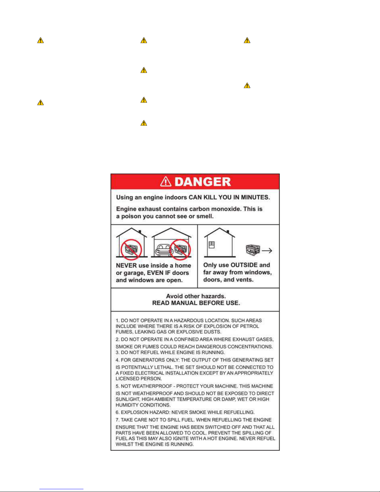
Fuelling Fuel is extremely
flammable. Keep clear
of naked flames.Do not
spill any fuel –do not
smoke near fuel or the
machine.
Always shutoff the enginebefore
refuelling.Do not fuel a hot engine –fuel
mayspillandcause a fire. Open the fuel
cap carefullyto allow any pressure
build-upinthe tank to releaseslowly
andavoid fuel spillage.Fuel your
machine onlyin well ventilated areas.If
you spillfuel,wipethe machine
immediately–if fuel gets on your
clothing,changeimmediately.To reduce
the riskof serious or fatal burn injuries,
check for fuel leakage.If fuel leakageis
found, do not start or run the engine until
leakis fixed.
During Operation
Make sure you always have good
balance and secure footing.Always be
awareof your surroundings and stay
alert for possiblehazards thatyou may
not heardue to the noiseof the
machine.Neverallowchildrento access
the machine.Avoid operatingwhile
people,especiallychildrenorpets are
nearby. To reduce the riskof injuryor
damage,do not allow anyother persons
withina radius of5 metres of your own
position.Toreduce the riskof damage
to property, alsomaintainthis distance
from other objects (vehicles,windows).
After Use
Always clean dust and dirt off the
machine –do not use any grease
solvents. Always keep the machine
clean, especially, the fuel tank, its
surroundings, and the air cleaner.After
the enginehas stopped, the engine and
exhaust components will still be hot.
Never place the machine in anyplaces
where there are flammable materials
suchas dry grass,combustiblegases or
combustible liquids etc. Let the engine
cool before storing the machine indoors.
Maintenance and Repairs
Service the machine regularly. Do not
attempt anymaintenance or repair work
not described in this instruction manual.
Have all other work performed by a
servicing dealer. We recommend that
you have servicing and repair work
carried out exclusively byan authorised
service person. Before proceeding to
adjust or repair the machine, be sure to
stop the engine and detach the spark
plug. Never attempt to make engine
adjustments while the unit is running.
Always make engine adjustments with
the unit resting on a flat, clear surface.
Replace any worn, damaged or
removed warning labels immediately. It
is recommended you complete formal
training on how to use your equipment
should you feel the need to do so.
Personal Safety
Stay alert, watch what you are doing
anduse commonsense whenoperating
a power tool. Do not use a power tool
while you are tired or under the
influence of drugs, alcohol or
medication. A moment of inattention
while operating power tools may result
in serious personal injury. Use personal
protective equipment. Always wear eye
protection. Protective equipment such
as dust mask, non-skid safety shoes,
hard hat, or hearing protection used for
appropriate conditions will reduce
personal injuries.

180714125800
3
3
WARNING! Risk of fluid injection
and blood poisoning. High
pressure jets can be dangerous if
subject to misuse. The jet must
not be directed at persons,
electrical equipment or the
appliance itself.
WARNING! High pressure
hoses, fittings and couplings are
important for the safety of the
appliance. Use only hoses, fittings
and couplings recommended by
the manufacturer.
WARNING! Do not use the
appliance within range of
persons.
WARNING! High pressure
cleaners shall not be used by
children or untrained personnel.
WARNING! This appliance must
be attended during operation.
WARNING! To ensure appliance
safety, use only original spare
parts from the manufacturer or
approved by the manufacturer.
WARNING! Do not use the
appliance if important parts of the
appliance are damaged, e.g.
safety devices, high pressure
hoses, trigger gun.
DANGER! Always wear approved
safety glasses . Wear protective
clothing to protect against
accidental spraying. Ear muffs are
needed in some areas where
water jet or engine results in
noise.

180714125800
4
4

180714125800
5
5
Parts Diagram
Engine Basics
Rear View Top View
View from side View from side (Diesel modelonly)
1. Air Cleaner(seealso11)
2. Throttlelever(seealso12)
3. Choke lever
4. FuelOn/Off
5. Fuel filler cap (seealso15)
6. Fueltank (seealso14)
7. Engine On/Off switch
(Petrol engines)
8. Pull start (seealso17& 23)
9. Exhaust muffler
10. Spark Plug (if equipped)
11. Air Cleaner(seealso1)
12. Throttlelever
13. Water pump (seealso18)
14. Fueltank (seealso6)
15. Fuelfiller cap
16. Engine On/Off switch
(if equipped)
17. Pull start
18. Water pump
19. Engine Oil filler cap
(Petrol engines)
20. Fuel Pump On/Off*
(*Diesel engines)
21. Engine Oil filler cap
22. Battery(if equipped)
23. Pull start
*Some engines feature 2 x oil filler plugs. (secondary)

180714125800
6
6
Water Pump –(machines smaller than 10hp)
24. Detergent Injectorconnector
25. Self-SuctionBleedervalve
26. Detergent tank
27. Thermalrelief valve
28. Detergent feedertube
29. Detergent tank connector
30. Plug for optional self-suction
bleedervalve.
31. High pressurewater outlet
32. Pressure limit adjustment(donot
adjustfactorysetting)
33. Water inlet quickconnector
34. Water inlet strainer/filter
Water Pump –(machines 10hp and above)
35. Shipping Bolt / Oil Filler plug (if equipped)
36. User adjustable pressure valve(if equipped)
37. Large typewaterpump
38. Oil levelindicator
39. Oil drainerplug
Ignition & Decompression (if equipped)
40. Key Ignition Start (if equipped) 41. Decompression lever

180714125800
7
7
Assembly
10hp+ machines only - Fitting the vent plug
INFORMATION! The shipping plug is a sealed plug used to prevent oil leaking during shipping and must be
replaced with the vent plug before use. The “vent plug” allows any pressure that builds up to escape while in use.
DO NOT operate this machine until the shipping plug has been removed and the “vent plug”is installed.
With the engine perfectlylevel:
1. Remove the “shipping bolt” (A) from the top of the water pump.
2. Screw the “vent plug” (B) in place of the “shipping bolt” (A).
This pump comes with pre-filled gear oil. For transportation purposes, it comes sealed. Please see below steps
for installing the breather plug.
Step 1: Ensure that the engine is upright and on even ground.
Step 2: Remove 8mm hex screw cap.
Step 3: Screw on red breather plug.
8mm HEX cap Breather plug

180714125800
8
8
Fitting the Wheels and rubber feet (if equipped)
NOTE! Some models come with Rubber feet already fixed to the frame.
The following step must be completed for each of the two wheel/axle sets.
Attach axle to wheels(some models are different)
1. Installing one side at a time simply slide one wheel onto the axle followed by one washer, pass the split pin
through the axle and bend the legs out and around the axle as shown.
Attach wheelsto frame
1. Insert the Wheel Axleinto the Frame Axle Tube.
2. The Locking Groove should align with the Bolt.
3. Tighten the Bolt.
4. Repeat this process to attach the 2nd wheel to the other side of the frame.
Attach rubber feet to frame
1. Attach rubber feet to frame.
2. Rubber foot: Install with a washer and a type 2 nut.

180714125800
9
9
Fitting the handle and hose holder (if equipped)
NOTE! Some models come fitted with a hose reel.
Handle (if equipped)
Push the handle down into the tube ends on the pressure washer frame as illustrated below.
Hose Holder (if equipped)
1. Insure a Nut has been threaded onto each side of the Hose Holder (image 1).
2. Insert the Hose Holder through the frame joining holes as illustrated in (image2).
3. Complete this step by carefully tightening the correct nuts onto the end of the Hose Holder (image2).
Gun and Lance Holder Hook
1. Insure a Nut has been threaded onto the “Gun/Lance holder hook” (image 1).
2. Insert the “Gun/Lance holder hook” through the frame holes as illustrated in (image2).
3. Complete this step by carefully tightening the correct nuts onto the end of the Hose Holder (image 3)

180714125800
10
10
Assembling the Gun (trigger) and Lance (tubing)
IMPORTANT!
Included hoses, connectors and tips vary depending on model.
The “drain cleaning tip” and the “small connector” is only available for some models and may be pre-assembled in
some cases.
The thread sizes on the “small joiner” are slightly different. Take care not to cross-thread.
Connections without black rubber O-rings inside are designed to be tightened with a small spanner.
If water leaks from a connector then optional Teflon plumbers tape should be used.
Connectors, drain cleaning tips etc. may be packed in different areas within the carton.
This diagram may show a different machine or different/optional accessories/hoses/lance tubes.
Some pressure washers have one hose permanently attached to a reel.
Pressure washers with a reel may also include a 30cm “reel connector” hose.
Assembling the turbo head
IMPORTANT! Plumbers PTFE Teflon Thread Sealing Tape is not supplied with the
machine. The tape allows a water tight seal of the connector thread when screwed in
to the turbo head. Teflon Sealing Tape is available from hardware stores and
plumbing outlets.
1. Wrap approximately 4 layers of Teflon Sealing Tapearound the threaded part
ofthe Turbo Head Connector (image 1) .
2. Screw the connector tightly into the turbo head (image 2-3).

180714125800
11
11
Assembling the Gun and Lance connections
A. Attach one end of the high pressure hose to the handle of the gun/trigger (A).
B. Attach the silver lance tube to the front of the gun/trigger (B).
1. Trigger/Gun 2. High pressure hose 3. Silver Lance tube

180714125800
12
12
Fitting the Hose connections
WARNING! Do not use hot water. Using hot water will damage your machine and void all warranty.
1. Self-SuctionBleeder
valve 2. Garden hose connector
(waterin)
3. Detergent injection inlet
4. High Pressure
connection (waterout)
5. High pressurehose
1. Attach “garden hose connector” to “water in” connection on the water pump (image 1 &2).
2. Connect water supply to “garden hose connector”.
3. Remove the clear plastic cover from the “water out” connector (image 3).
4. Connect the end of the “high pressure hose” to “High pressure connection” on the water pump outlet
(image 4& 5).
Connecting the Battery (if equipped)
Locate the two battery plugs near the battery (if equipped) and connect by pushing them together.
NOTE! The battery is self-charging through general use however there may be need on occasion to remove the
battery and charge it with an appropriate charger or jump start the engine(selected 4-Stroke petrol and Diesel
versions only).

180714125800
13
13
Before Use
WARNING! Lock the wand securely or it could be ejected
under high pressure when operating the gun, possibly causing
injury or damage.
WARNING! Add engine oil to the correct level before
operation. Failure toadd engine oil will destroy the engine.
Engine damage caused by lack of oil is not covered under
warranty.
ATTENTION! The pump units on most 7-10hp models are a
sealed unit that has been pre-oiled. Sealed units feature no
shipping or vent plug. Do not attempt to add extra oil to the
sealed pump units.
ATTENTION! For safety the connection plugs may have been
disconnected from battery (if equipped) before shipping.
Please follow the steps in the section “Connecting the battery”
to connect your battery.
ATTENTION! The water pump “vent plug”must be installed
prior to starting the engine or damage can occur (10hp+
machines only) see section on fitting the “vent plug”.
Check that oil has been added to the proper level in the engine
crankcase (see section adding oil)
Add the correct fuel to fuel tank (see section adding fuel)
Check all attached hose connections are secure.
Check tomake sure that there are no kinks, cuts, or damage to
the high pressure hose.
Ensure your water supply is ready and available (never run the
pump dry!).
Read and understand this manual before using the pressure washer.

180714125800
14
14
ATTENTION! Your pressure
washer “ENGINE”IS NOT
shipped with oil, you must add
oil prior to first use.
ATTENTION! Your pressure
washer “PUMP”is shipped with
oil; there is no need to add oil to
the pump.
WARNING! DO NOT operate this
machine until the “shipping plug”
has been removed and the “vent
plug” is installed (10hp and larger
models only)
ENGINE Oil
WARNING! Using the wrong oil
can damage your engine and void
warranty.
Acceptable Oil Grades: 10W30 /
10W40 / 15W30 / 15W40.
WARNING! Do not overfill or tilt
while filling.
With the engine perfectly level:
1. Remove the small engine “oil filler plug” on the side of the engine.
2. Fill with recommended oil until oil starts to run back out of the filler
hole.
3. Replace the “oil filler plug”.
4. Clean up any excess oil around “oil filler plug”
PUMP Oil (10hp and larger models only)
ATTENTION! Your pressure
washer “PUMP”is shipped with
oil; there is no need to add oil to
the pump
IMPORTANT! The smaller pump
types (less than 10hp) are a
sealed unit and do not require
maintenance. Any attempts to
service or alter the pump may
damage your pressure washer
and void your product warranty.
WARNING! Using the wrong oil
can damage your engine and void
warranty.
Acceptable Oil Grade: 80W-90,
SAE 90 or 85W-90 Gear Oil only.
ATTENTION! The water pump
“vent plug”must be installed prior
to starting the engine or damage
can occur (10hp+ machines only)
see section on “fitting the vent
plug”.
INFORMATION! The shipping
plug is a sealed plug used to
prevent oil leaking during shipping
and must be replaced with the
vent plug before use. The “vent
plug” allows any pressure that
builds up to escape while in use.
1. Ensure your engine is on a level surface.
2. Remove the vent plug (A) from the top of the water pump and set aside.
3. Fill with the specified oil type until the oil level reaches the red dot (or mid-section) of the oil level viewing
window (B).
4. Replace the breather plug and clean up and excess oil around the pump with a clean disposable cloth.

180714125800
15
15
Adding Fuel
WARNING! Do not use fuel
substitutes such as ethanol,
methanol or biofuel in your
engine, using such fuel will cause
damage and void any applicable
warranty.
WARNING! Use only clean, fresh
non-ethanol 95+ unleaded or
fresh clean commercially
available pump Diesel. Only use
the correct type of fuel for your
engine.
ATTENTION! Be sure to confirm
whether you have purchased a
4stroke petrol or Diesel model by
looking at the original website you
purchased from and refer to the
corresponding section below.
ATTENION! Before refuelling
ensure the engine is switched off
and has cooled
NOTE! It is normal for smoke to
be emitted from the exhaust of a
new engine for the first 5 hours of
use while running in.
1. Clean surface around fuel cap to prevent contamination.
2. Loosen fuel cap slowly. Rest the cap on a clean surface.
3. Carefully pour fuel into the tank. Avoid spillage.
4. Prior to replacing the fuel cap, clean and inspect the gasket.
5. Immediately replace fuel cap and hand tighten. Wipe up any fuel spillage.
Non Self-Suction Operation (pressure or gravity fed water supply)
1. Remove and dirt or foreign matter from the gun outlet and the make connector of the wand.
2. Make sure the water supply is connected and turned on.
3. Squeeze the trigger on the gun until there is a steady flow of water coming from the nozzle.
4. Start the engine.
Self-Suction (Optional “bleed valve”required)
NOTE! This process takes between thirty and sixty seconds, depending on the length of the inlet hose with a
maximum allowed length of 5 meters.
NOTE!*If you would likeadd self-suction feature to your machine simply visit our website www.mytopia.com.au
and search for “bleeder valve” to purchase this optional fitting.
WARNING! Do not run your pump dry during this process for more than 60 seconds.
1. Make sure the water supply is connected to the pump.
2. Start your engine (see section starting the engine).
3. Run the engine at mid-range (half throttle).
4. Locate the “bleeder valve*”on the pump and turn anti-clockwise three full turns.
5. Simultaneously allow air to escape from the “bleeder valve and hose by squeezing the trigger on the gun until
there is a steady flow of water coming from the “nozzle”.
6. When there is a steady flow of water from the “bleed valve”and “nozzle”and air is completely expelled; close
the “bleed valve”by turning clockwise until tightly sealed.
7. This process will need to be repeated if any air is allowed to enter the inlet hose.

180714125800
16
16
Using the Quick connect nozzles
CAUTION! Turn engine off when
charging nozzles.
CAUTION! Injury/damage risk:
Nozzle will launch if not attached
correctly.
CAUTION! Spot test an
inconspicuous area to determine
if pressure spray or detergent is
likely to affect the surface.
WARNING! High pressure spray
can damage some surfaces.
CAUTION! Make sure you hear
the "click" when inserting the
nozzle tip into the quick
connection.
CAUTION! Pull the nozzle to
make sure it is seated properly
before operating your unit.
WARNING! Risk of fluid injection
and blood poisoning. To avoid
serious injury never point spray
nozzle at yourself, other persons
or animals.
The colour-coded quick connect nozzles provide a wide array of spray
widths from 0° to 65° and are easily accessible when placed in the
convenient nozzle holder. When using the pressure washer, select the
nozzle suitable for your job. The machine must be turned off before
attempting to change the nozzle to prevent injury due to accidental high
pressure activation. If a nozzle becomes blocked, use some wire to clear
the blockage. The nozzle must be removed from the machine before
attempting to clear the blockage to prevent injury.
To change the nozzles on the lance:
1. Pull the quick connect coupler back and insert nozzle.
2. Release the quick connect coupler and twist nozzle to make sure it
is secure in coupler.
Nozzle colours may vary depending on model/batch. Inspect before use.
0° Blasting nozzle = Red nozzle
Application: For stubborn grime. Not recommended for
soft materials like sidings, decks, painted surfaces or cars.
15° Stripping nozzle = Yellow nozzle
Application: Intense cleaning for smaller surfaces.
25° Cleaning nozzle = Green nozzle
Application: For dirt accumulation over a large surface.
Turbo Head = Large Black nozzle
Application: High pressure cleaning for large areas.
40° Washing nozzle = White nozzle
Application: For moderate dirt accumulation over large
surfaces.
65° Detergent nozzle = Black nozzle
Application: For operating with detergents or cleaning with
low pressure.

180714125800
17
17
IMPORTANT! If a nozzle becomes blocked, use some wire to clear the blockage. The nozzle must be removed
from the machine before attempting to clear the blockage to prevent injury.
Detergent injection
CAUTION! Some machines have been designed for use with liquid detergents
Never use the following in your pressure washer;
Bleach, chlorine products or other corrosive chemicals.
Tri-sodium phosphate products.
Ammonia products.
Acid-based products.
These chemicals will harm the unit and will damage the surface being cleaned. Use of these items will void all
warranty. Use a standard liquid car wash or similar detergent.

180714125800
18
18
Starting the engine
CAUTION! The starter grip can be drawn back very
quickly before you can release it. This may pull your
hand forcefully toward the engine and cause an injury.
CAUTION! Do not allow the starter grip to snap back.
Return it slowly by hand.
Petrol Four Stroke Engines
1. Turn the “Fuel Valve” (A) to “ON”.
2. Set the Choke (if equipped); move the “choke lever” to the left (“Cold Start” position).
3. Move the throttle lever (C) half way between FAST and SLOW.
4. Start the engine:
a. Turn the “Ignition Key” to “ON”(if equipped) otherwise turn the engine switch to “ON”
b. Key Start (if equipped): If the battery has enough charge, use the ignition key to start the engine by
holding the key in the “Start” position for a few seconds (New batteries can have no/little charge; use pull-
start, jump start or change battery if needed)
c. Pull Start (if equipped): Pull the start grip until the engine starts (E).
5. Move the “Choke Lever” to the right (“Run” position).
6. Set the throttle lever (C) at the desired speed.
IF ENGINE WILL NOT START:
1. Repeat the process above but place and leave the “Choke Lever” to the right.
2. Check Oil Level.
3. Charge battery or jump-start if needed (If equipped).
4. See section “Troubleshooting”.

180714125800
19
19
Diesel Four Stroke Engines
Side of Engine Top of Engine
1. Turn the “Fuel Valve” (A) to “ON”.
2. Turn fuel pump to “RUN” position.
3. Turn the “Ignition Key” “ON” (if equipped) or the engine switch to “ON”.
a. Key Start (if equipped): If the battery has enough charge, use the ignition key to start the engine by
holding the key in the “Start” position for a few seconds (New batteries can have no/little charge; use pull-
start, jump start or change battery if needed)
b. Pull Start (if equipped): Push the decompression lever “down” then pull the start grip until the engine
starts (E). Note: Each time you pull start you will need to push the decompression lever down or the pull
start will be difficult to use.
IF ENGINE WILL NOT START:
1. Check Oil Level.
2. Charge battery or jump-start if needed.
3. See section “Troubleshooting”.
Re-Priming the fuel system (Diesel engines only)
Occasionally, when an engine is new or has been run completely out of fuel it may be necessary to “reprime” the fuel
system. This is simply removing any air bubbles from the fuel line.
1. With the fuel tank full of fuel and the fuel tap “ON”, remove the fuel line
from the engine by using a pair of pliers to unclip the hose-clamp.
2. Allow fuel to flow out until there are no more air bubbles. This can be a
messy process souse an absorbent rag to catch all the fuel running out
of the line.
3. Push the fuel line back onto its connection point and re-fasten the hose
clamp.
4. Clean up any spilled fuel.
5. Attempt to start the engine.
This manual suits for next models
8
Table of contents
Popular Pressure Washer manuals by other brands

Bosch
Bosch Fontus Original operating instructions

cecotec
cecotec HYDROBOOST 1500 EASYMOVE instruction manual

Simpson
Simpson 7108644 use and care manual

Troy-Bilt
Troy-Bilt 20210 owner's manual

Kärcher
Kärcher K 5.55 Jubilee instructions

A.R.North America
A.R.North America AR112 Operating instructions and parts list