SENDING DATA TO A COMPUTER
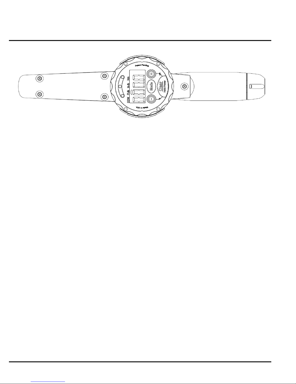
Fig. 9
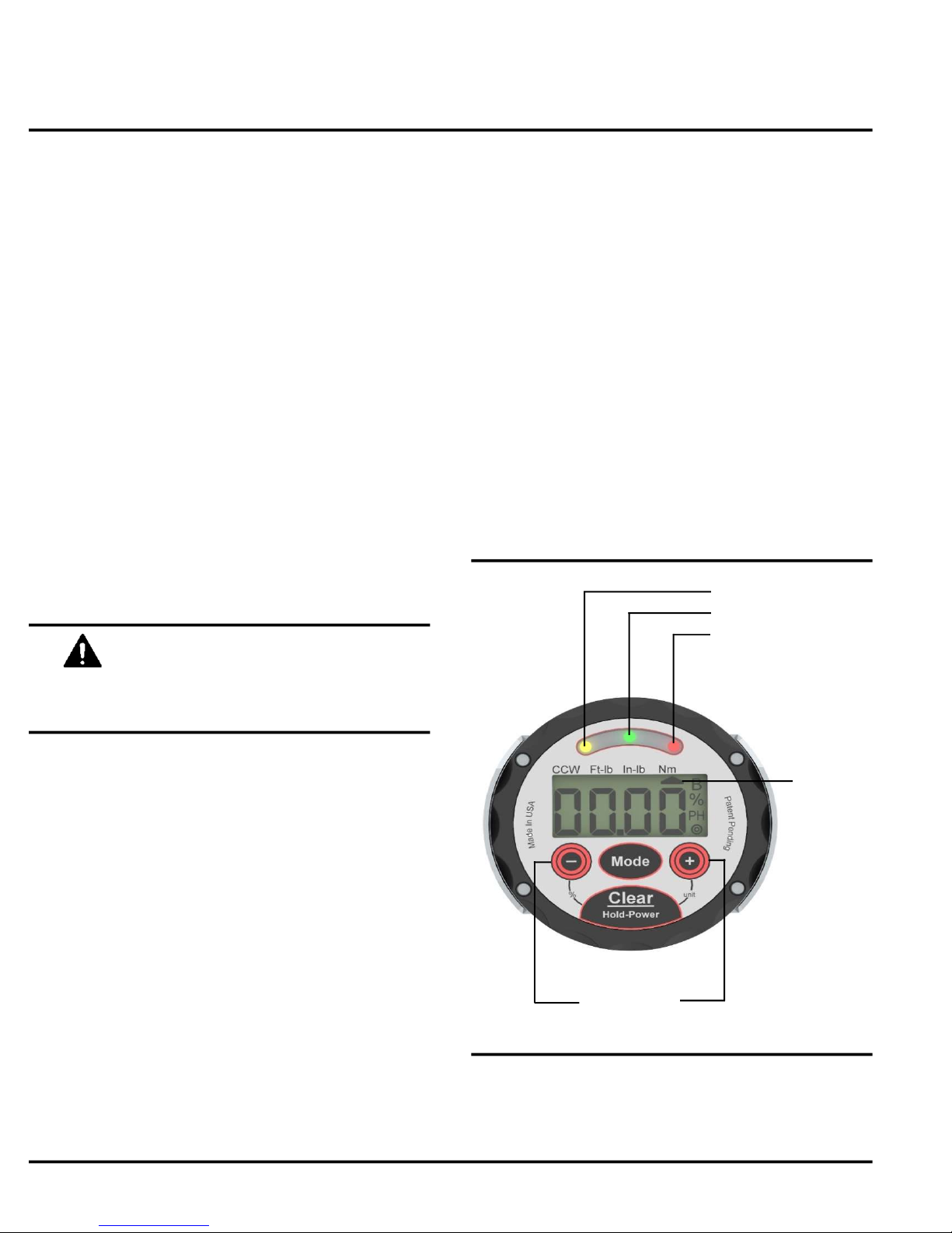
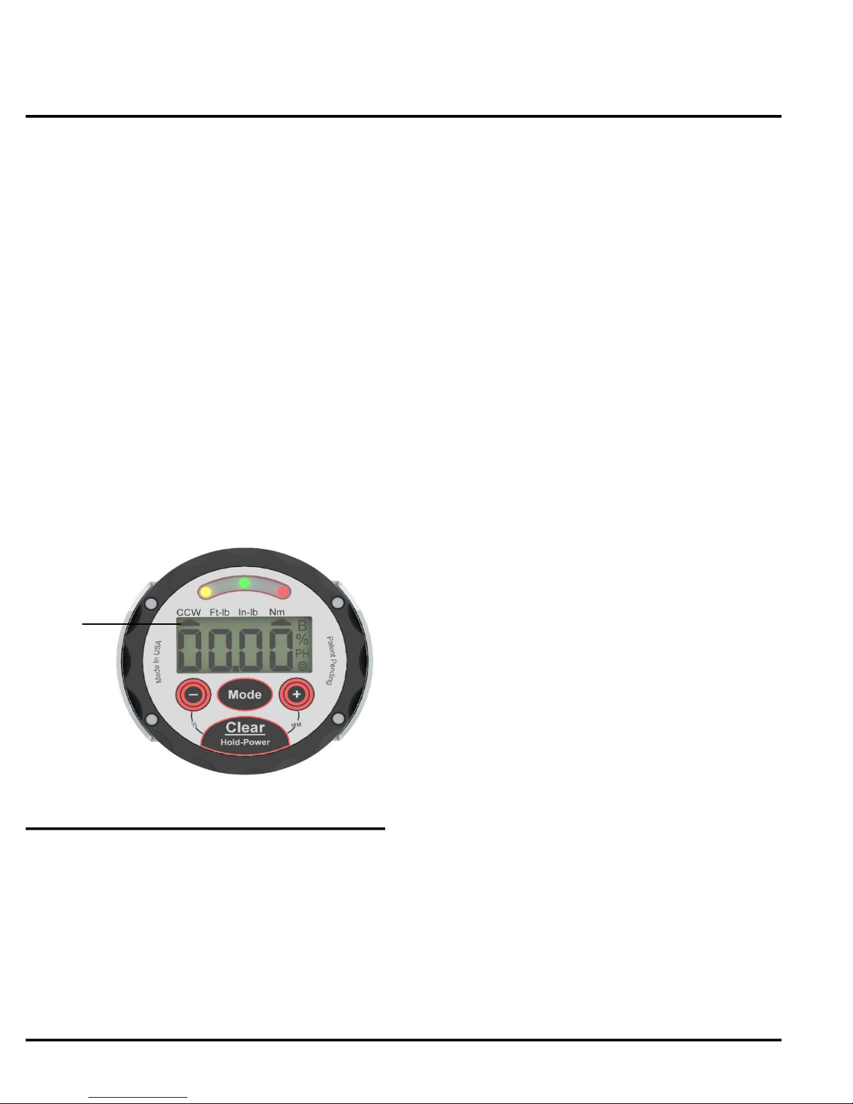
Fig. 10
Jetco Torque Tools
OPERATION OF POWER WRENCHES
7 www.itorque.com
■ Connect the data/power cable to the wrench.
■ RS232 Kit only: Connect the 110V transformer to
a wall outlet and batteries will begin to charge.
■ USB Kit only: Connect the USB cable to the USB
wall transformer or USB port on a computer and
batteries will begin to charge.
NOTE:
■ The wrench can be used while charging batteries
or on external power without batteries.
■ Batteries can be charged while sending data to a
computer.
Do not install non-rechargeable batteries
in Power wrenches ("-P" and "-USB"
models) or damage will occur.
NOTE:
■ To send data to a computer, the computer must
be equipped with software capable of capturing the
data sent by the wrench.
■ The following are some programs that are
recommended for this task:
- HyperTerminal (Included in some versions of
Windows)
- DATASNIP (free download)
- Winwedge or Winwedge Pro
Please contact JETCO if you have any
questions regarding the use of software.
SENDING DATA TO A COMPUTER
■ Plug the RS232 adapter into a 9 pin serial port on
your computer or if equipped with a USB cable,
plug it into a USB port on your computer.
■ RS232 Kit only: Plug in the 110V transformer into
a wall outlet.
■ Connect the data/power cable to the wrench.
■ Turn on the wrench and set the mode to PEAK
MODE.
■ Press the CLEAR key to send data to the
computer.
NOTE:
See Figure 9 & 10
■ The following information will be sent
automatically:
- Torque value (+ for CW, - for CCW)
- Units
- Target Torque Setting
- Target Zone Setting (%)
- Low/Pass/Fail Condition
■ Data is sent in standard ASCII text format.
Communication Protocal:
9600 Bps,8 data bits, no parity, 1 stop bit
■ To send information directly to a spreadsheet or
word processor, the user can copy and paste, save
and import text files (from Hyperterminal) or
download a "wedge" program that will send data
directly. DATASNIP is recommended, visit:
www.priority1design.com.au/datasnip.html
to download a free version of DATASNIP.